My M2 project, Trimble Base Station

First I want to thank Torriem of the Combine Forum for the initial research and Arduino Sketch for the 1008 inject.

A huge thankyou to PotatoFarmer! He helped me understand/learn/utilize the Nano. He also modified Torriem’s sketch so that it only utilized the single serial port that a Nano has, skipping the whole softwareserial headache. He has been a big help in answering all my n00b questions.

I also want to thank bide from this forum for his idea of using a Pelican box as a project box. Does anyone make a waterproof case for reach devices? - #10 by Rabun

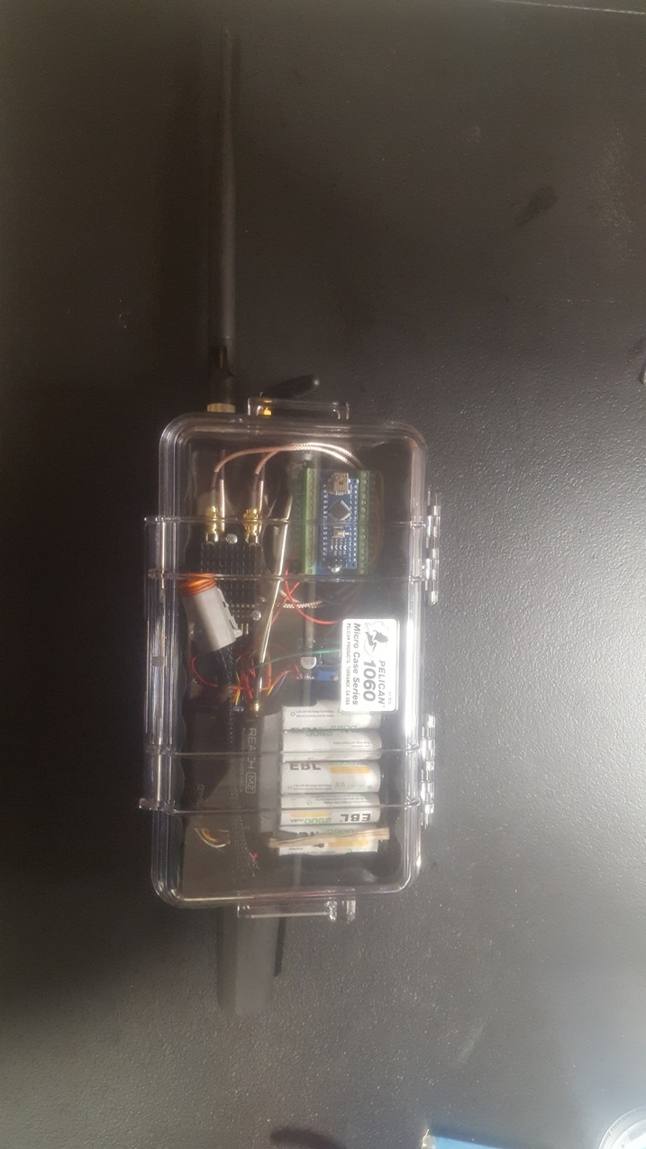
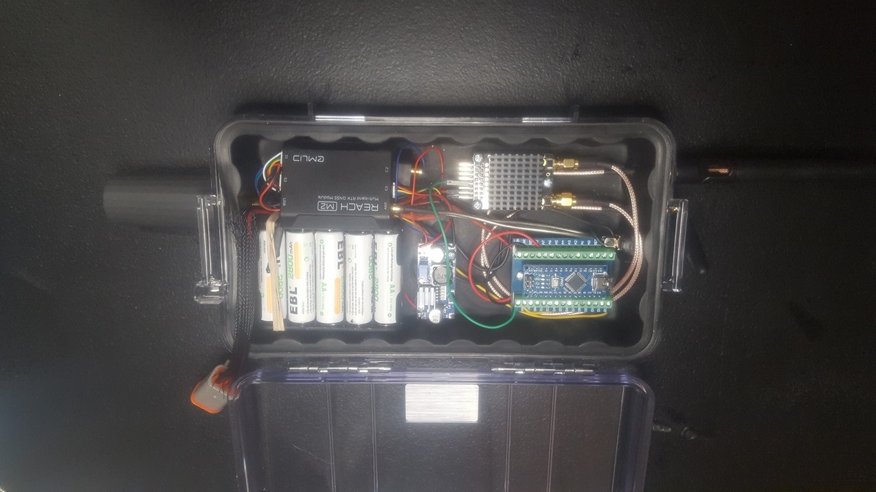
Now for the project. I wanted to utilize a M2 as a Trimble base station. I needed to take the RTCM from the M2 run it through a Nano that has the 1008 inject so that the Trimble monitor could utilize the data. This worked very well.

I wanted it to have its own power source so I purchased a battery holder case for 10 AA rechargeable batteries (12V/1.2V per battery). Tenergy has a handy smart charger that I added to the system to charge. I put a on/off switch in the power supply and connected the battery output to a buck converter to reduce it to 5.5V which has separate leads to the M2 and the radio. I have the LoRa radio in the box as well in hopes that at some point I can use both the 3DR radio and LoRa simultaneously. I used cabled bulkheads from the GPS and radio outputs. Currently, I have the normal M2 GNSS multiband antenna on top. I have an extension cable but, I am purchasing a SwiftNav antenna later. I will change the bulkhead from SMA to TNC at that point.
I then needed to communicate that data to the Trimble monitor. I initially utilized two 3DR radios for this. I have since changed the base to a RFD900 radio for a higher output for distance in a field.

![FMX_RTK|309x550]

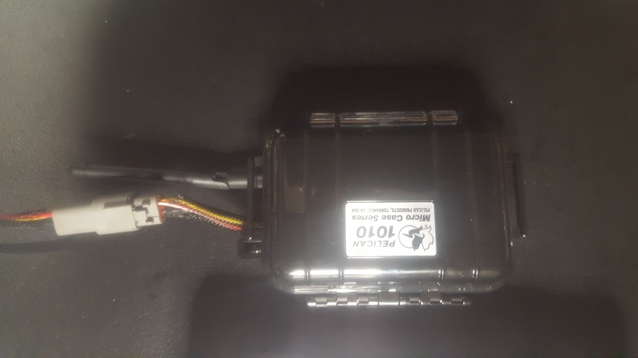
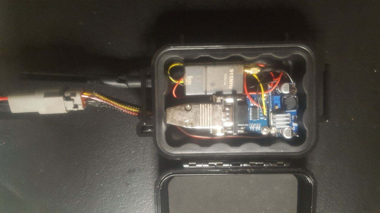
I made a radio box that plugs into the Trimble monitor (FMX for those that are wondering). The radio box consists of a 3DR radio, a TTL to RS232 adapter and a buck converter. With this, the Trimble monitor supplies the power, the buck converter changes it to 5.5V, the TTL to RS232 converts the 3.3V serial signal to 5.5V RS232 which is what the Trimble monitor needed.
Plugged in and working! Looks good too!
(upload://9jPv8g4dbftyekHLxTXj028rJsj.jpeg)

![radio_interior|600x337]

My next project is attempting to get RTCM out through both the 3DR and LoRA. If I complete that the project after that will be a RTCM to CMR+ converter. Wish me luck.

8 Likes

Not sure why but the forum rotated all my pictures. Sorry they are upside down.

Also, I forgot to attach two.


4 Likes

Congratulations…nice looking results with the M2 from the GPS Diagnosis page. Why need two radios though?

For Radio Correction, why couldn’t you use the TNC RTK port behind the FMX display? Oh I see the power requirement now, my bad. What port you using on the FMX to send the radio signal in after the fact?

Last question, why won’t the Trimble RTK antenna kit work with your setup?

Looks really good!

What are you going to do with all the cash you saved? :rofl: Buy a car? :joy:

The two radios are more like the classic modem / data radio setup. He is running externals to get more watts, no data bills, and more distance. Also the externals can handle a higher data rate. JP could also replace the radios with cellular modems too for unlimited distance, but in exchange for a monthly bill.

With a higher data rate he can use 5Hz corrections or maybe more, and get some mega on the fly moving accuracy. Really handy in higher speed equipment like an Ag sprayer or a Land Scraper.
Just about everything is fine at 1Hz corrections, but when you have 10hz update on both position and corrections it is a very special feeling from the drivers seat. But 10X more costly over cellular, and generally unavailable for purchase without custom equipment.

This is a portable Trimble high refresh base only $24,000 CDN in value.

Let the dirt work begin!!!

2 Likes

Your not a N00B, maybe just rusty.

1 Like

Trimble, like many others, use a proprietary 900 mhz radio. I have a SNB900 which is a Trimble radio or repeater but, it only transmits CMR data not RTCM.

You can port in RTCM or CMR via port C or D.

A Trimble base unit new is only $13,750 US currently, used is bringing $6,000 to $8,000 for a current model and $4,000 to $6,000 for an outdated unit no longer in production.

Also, along with my base project, I will be porting in two RS2 units to control a 24 foot box scraper. We mount a receiver on both sides of the blade. With this setup, my FMX or TMX monitor only needs GPS1 unlocked to RTK. I will do the Auotpilot steering with GPS1 and grade control with the two RS2’s. If I do that via all Trimble buying it new would be almost $60,000. Yes I can afford to tinker.

The nice thing is, after you have setup the changes in the monitor to receive the RTCM via port D, the rest is plug and play.

The only update I am waiting on from Emlid is to store base location data. When doing land leveling/sloping or sub-surface drainage tile, you do not get the job done in one day. When you setup your base station it has to have the same physical location and the same electronic location i.e. Lat/Lon/Alt. That way, all of yesterdays data matches up with the next 2 to 5 days that it takes to complete the job. There is a work around on the Trimble side. You have to create a benchmark before doing any grade work with WM-Drain or Field Level II (The Trimble monitor grade work applications, WM-D is for linear work like field tile or surface drains and FLII is for area work like land leveling/sloping). When you setup your base if you do not set it up with the same Lat/Lon/Alt you can go to your master benchmark and re-bench which makes all the data reflect the same. It is kind of a hassle though. Much easier with a stored base location in the same physical location, no re-bench needed.

A lot of people do not realize what a difference there is when creating a new base even in the same location. If you are not doing it with average fix, there can be as much as 10 feet difference North/South/East/West and up to 30 feet difference in Altitude. When the Altitude dictates what height is the starting and finishing point that is way too much. If you are using NTRIP and average fix I have still seen a 1 inch variance in Altitude.

BTW, I am a Trimble Dealer. I am looking at selling used units. I can put a used unit together with steering dual receivers for grade work for less than $25,000. That is a Trimble monitor unlocked to RTK with the WM-Drain and Field Level II unlocks, used NAV controller, new AutoPilot vehicle interface kit, M2 base station, two RS2 with cables, and the valve module kit to automate the grade control on the tile plow or box scraper/land leveler. This is installed with dealer support. New this would be more than $70.000 and that is a lot of clams.

5 Likes

Not only the data bill but, your accuracy diminishes with distance. Unless I could find out how to setup an affordable VRS NTRIP system it isn’t feasible Ntrip is easy but usually a single base solution that can be miles away. For vertical accuracy you want to be within a 2 mile radius of your base. A VRS system creates a virtual reference station or point and all corrections are based off that utilizing 3 or more actual base stations.

5 Hz has kind of been an industry minimum. We are normally traveling a minimum of 1.2 MPH and up to 10 MPH depending on if we are tiling or land leveling.

Not only is it a much more affordable system, I have made it where it is almost plug and play after initial setup.

Dirt is moving and drain tile is in the ground!

4 Likes

BTW, Trimble Ag base stations can only put out CMR. If I want to use my RS2’s in the mix, that is another issue.

Yes completely and just the added lag makes it a little less accurate too. By the time you get it on the net to the server, processed, off the cell tower to the machine you add an extra 200-400ms, does not sound like much but 10hz is 100ms intervals.

So your corrections may be 2 or more readings in the past before you receive it and can process.
it. Ublox says to keep corrections below 500ms from acquisition to delivery for best results.

Super short baseline and near instantaneous correction delivery really makes a difference.

4 Likes

In AG , there’s little obstruction so an upward oriented base radio should always suffice.

When using say an SPS 855 or some other Trimble AG Base Station, here is cool, I find the Benchmark/Re-bench as a decent practice. AG Reseller as well.

Single Bucket with two RS2 is nice, haven’t had the opportunity to install two antenna on either side of the bucket. I always imagined it’s for levees and sloped Levelling

How many Hectares could you Level to design in those 2-5 days, WM-Form for Designs? Soil Type? Hard Pan?

Isn’t this a conflict of interests?

80 acres so 33 Hectare in 3 days. Not too many fields larger than that around here. Our soil is heavy clay. We have about 6 inches of top soil then nothing but yellow waxy clay to the bedrock.Around here, we are extremely flat, there is a .05 slope in the ground naturally, sometimes in the wrong direction as well. We are normally just doing a dual slope to a square field that will have a perimeter drain ditched on both down slope sides. We are trying to do so with the minimum amount of dirt moved, no more than 2" are taken from any one location if we can avoid it, 3 if we have to.

We have done an omni-directional a few years back but Trimble did not have their WM-Form out at that time. We used Optisurface then. We are considering using WM-Form as we have a couple customers that want us to do some work north of here where it gets more rolling.

I am not sure what you are saying is a conflict of interest. Selling used equipment or an Emlid base with a used unit. Either way, neither is a conflict. There are dealer out there on the Ag side that sell Trimble and Ag Leader new. To me that is a conflict of interest. That would be like having a Chevy/Ford car sales or JD/CNH tractor dealer.

Also, most that are looking for used are looking for the lowest $$$ amount to get into a system. Normally, they would never consider new.

3 Likes

The other thing I was able to do this weekend was find a working version of MultiPoint SiK software that works on my low $$$ 3DR radio. I found the one I needed for my RFD00+ on their website. I scoured Google for a couple hours before I found a working version. I needed this as at times I can have two or three rovers getting signal off one base.

I tested it with my two 3DR radios and used my extra RFD900. I had the RFD communicating with both so voila multiple rovers.

1 Like

One thing I forgot to mention in the original post was I also have the Emlid LoRa radio below the M2. If I want to use it with Just the RS2 I can change the RTCM output to LoRa and go to work. I didn’t have my LoRa antenna when I took the pictures. The port for it is to the right of the RFD900 antennas. Being there is only one RTCM output at a time, there shouldn’t be any radio conflict. As a precaution, I might put an on/off/on switch or an A/B switch in the system so only the correct radio is powered.

1 Like

Neat project. Funny that I chose a Pelican 1010 case for my own setup but since I only want to do single unit static survey with it, battery + receiver fits in that small case.

1 Like

Like I said in the initial post, thanks to Bide for the idea. I forget what I was searching for but I liked the idea. It was a nice case and very affordable.

I went with the 1060 to give me room for all the components batteries/buck converter/Nano/M2/LoRa radio/RFD900+ radio. It worked out very well without crowding.

I have two more additions to add to the 1060 box for bench testing purposes. I am adding a DHT11 temp/humidity sensor and a digital readout. I want to see what the internal temp reads in a controlled environment then later this summer what it reads when it is say 80-90 degrees F outside. If it gets too hot, I am going to change my case to my original idea of a 4 or 5 inch PVC pipe with ventilation holes and a circulation fan via a laptop fan controlled by the Nano if it gets to hot inside.

The 1010 worked great for the radio only unit!

1 Like

Here is a link to one of our videos.

It is using Trimble dual globes on the 24’ box scraper. He was also hand jamming the steering.

BTW, when the video starts the far away woods is a mile away. Yes, we are flat!

2 Likes

Yup that is flat-landing, were do you put the water when it rains? (lol wherever that Deere is headed)
But you can run a 60ft header on that land no issues!

Here is what is classified as “gently rolling”, we also have hills in the class of “Unfarmable”. So wild how different the topology of this planet is.

2 Likes

Actually, the area of Ohio where I live was what was called the Black Swamp. It was drained in the late 1800’s and early 1900’s. Basically they dug a bunch of man made ditches which drain to a local creek which drains to one of the rivers and goes to Lake Erie from there.

Everything is 1 mile square around here. Roads are almost true North/South or East/West unless it is an old river trail near one of the natural rivers. Along about every road is a drainage ditch varying in depth from 3.5 feet to 18 feet deep depending on where you are and how far or close to the creek/river. At about 25 seconds into the video, you can barely make out one of the ditches. It is grassed and between 5 and 6 feet deep. Nice thing about the number of ditches we have is we do not have to go far to drain an main tile outlet which helps keep our pipe sizes smaller.

For those that haven’t been around sub-surface drainage here is a quick lesson on how we do some things.

  1. Install a main tile which drains to a ditch/river. This tile is somewhere between 6 inch ID to 18 inch ID around here. the size of the main is determined by how much slope you are able to install it with along with how many acres are draining into it and what the drainage coefficient of the soil is. Basically, drainage coefficient is how fast or slow water permeates through the soil. Here it is very slow as we only have about 6 inches of top soil then a yellow waxy clay.

  2. Install laterals systematically or in a pattern. Because water doesn’t permeate our soil very well, our laterals are spaced ever 15 - 33 feet apart and shallow 2 - 2.5 feet, compared to most areas that are 3 - 3.5 feet deep.

As an example, I did a screenshot from Google Earth. In the current picture on Google Earth,

you can somewhat see the lateral tile lines. They are running East/West and 25 feet apart. I go back in Historical Imagery and find a better view. They normally show well in the spring and fall months as the soil above them are dry and almost white looking where the area between is dark as it is still wet. The attached image was taken 9/2014

4 Likes

I got one of my final additions to my base station project in this week.

Initial tests look very good.

1 Like