How to set the antenna height for RTK?

Let’s move to the field today. When you’re setting up your receivers for RTK, among other things, you need to set the antenna height: on the Survey tab on the rover and the Base settings on the base. How to do that right?

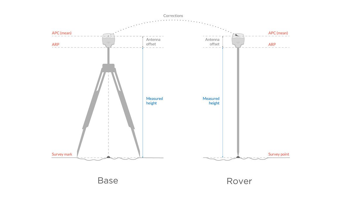
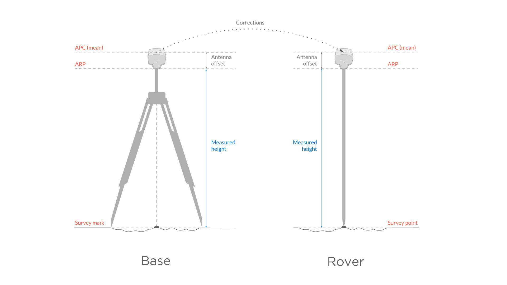
All GNSS observations refer to the antenna phase center (APC) of the receiver. The antenna is located inside the device, so it’s not convenient to work with its coordinates. A surveyor usually needs coordinates of points on the ground—whether you use a known point to place the base, or collect points with the rover.

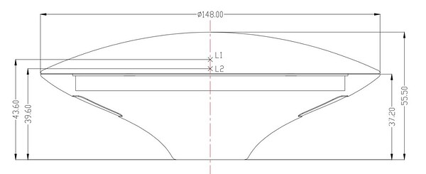
The height from the point on the ground to APC is a sum of the distance from the ground to the center point on the Reach’s bottom, antenna reference point (ARP), and antenna offset. The first of them is exactly what you need to measure and enter in the app. Usually, it’s just a tripod with an extension pole or survey pole height. The offset between the ARP and the APC is considered automatically by Emlid Flow (formerly known as ReachView 3).

And what is the math of it? Let’s check it for base and rover separately.

Base height

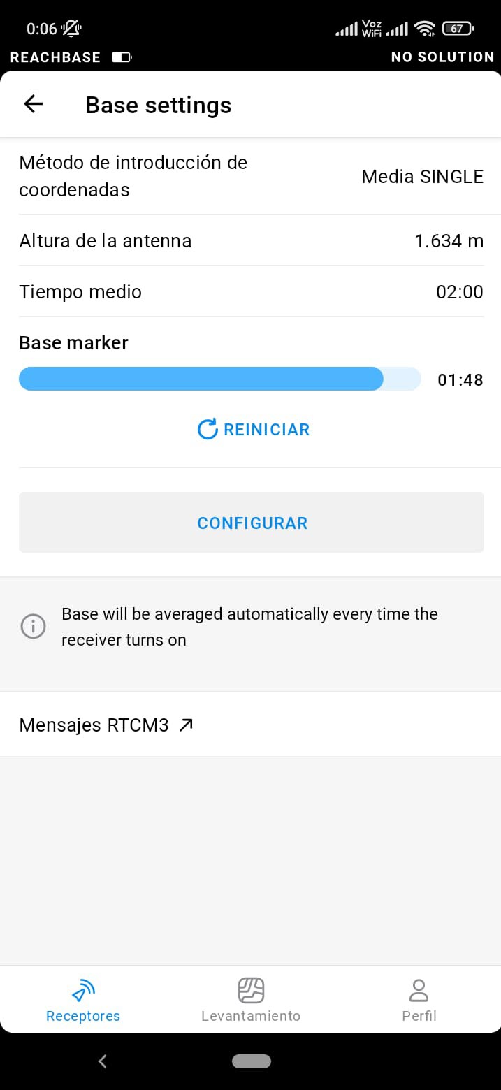
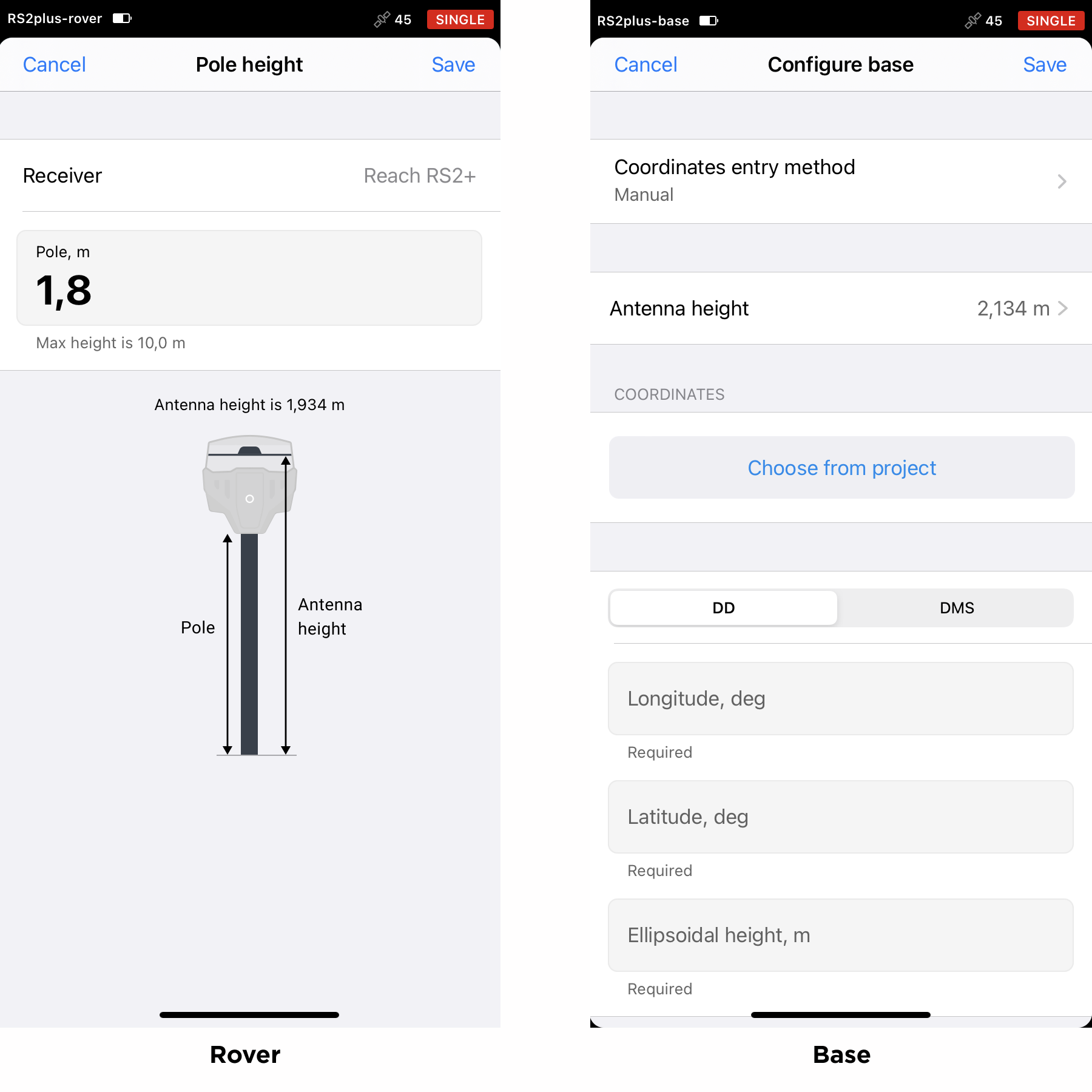
The base needs to transmit its APC position to the rover. But when you enter known base coordinates using the Manual coordinates entry method, they usually refer to the point on the ground. So, Emlid Flow takes the measured antenna height to calculate the APC position and sends it.

If you use the Average coordinates entry method, you have the APC position right away. So you don’t need to do anything additionally.

By the way, starting from the 30 Reach firmware, if you go to Manual entry after averaging and specifying the antenna height, Emlid Flow will calculate the point on the ground. You can save this position and use it for future surveys.

Rover height

In RTK, the rover calculates the coordinates of its APC. To find the coordinates on the ground, specify the pole height in the corresponding menu before collecting or staking out points on the Survey tab so that Emlid Flow could subtract it from the original measurements.

This is all about setting the antenna height for RTK. If you still have questions, feel free to share them in the comments. Next time, we’ll figure out how to handle the antenna height for PPK.

P.S. Don’t forget to check our previous post about choosing an NTRIP service to work with Reach RX.

16 Likes

Feature request:
Use the ARP and APC terminology in the App. That would make it so much easier to understand, and it is common GNSS terminology anyway.

6 Likes

I would use only ARP or bottom of antenna for EMLID, the APC is not the same for L1 and L2. With the drawing in RV3 is good to understand how it the h reference.

My humble opinion

5 Likes

Agree on that as well, yep.

2 Likes

Setting the units up is one thing. Interpreting the exported CSV needs equal explanation. With particular emphasis on the elevation. As mentioned in a previous reply, consistency in emlid terminology would go a long way please. I’m mainly referring to the treatment of the 0.134mm.
Thanks

Hi Christian and Bernardo,

I agree with you regarding ARP and APC—it is a part of common GNSS terminology. But we designed the app in the way so that users from non-GNSS spheres could work with it without deep learning GNSS theory. I believe it makes the app a bit more user-friendly.

Anyway, I’ll note your thoughts. Thank you for sharing them.

1 Like

Hi Troy,

In CSV file, you see the coordinates and height of the point on the ground. This height already considers the antenna offset for the receiver (for Reach RS2/Reach RS2+ it’s 0.134 m) and the measured height you entered for the rover in ReachView 3. The sum of these 2 values gives you the antenna height, which is also written in a separate column.

3 Likes

I acknowledge that, and see the very logical reasoning, but it is simply more confusing the current way.

In my mind, there should be no mention of the APC, only the ARP. The APC is something very diffuse, and even physically invisible, and it is also an approximation (the average of L1/L2).

However, the ARP is very tangible. You can see it, you can measure to it.

6 Likes

Hmm, yeah, I see your point, Christian. And I agree with you in a question of terms. It sounds well-founded. I noted it.

Thanks for sharing your view!

2 Likes

If the antenna height is already set in Reach View, do I skip inputting antenna height in Qfield?

Hi @AdamHz,

That’s a good question. Thank you!

When you set the antenna height for the rover, it is applied to all the points collected or staked out directly in ReachView 3. But the position stream from the receiver doesn’t include this info. That’s why if you integrate Reach with 3rd-party software, you need to set the antenna height there additionally.

3 Likes

Thanks for the answer. The antenna height thing was a little confusing and I was mapping out an area and I had to be sure.
The device worked brilliantly.

Adam,

I’m glad to hear that! :slight_smile:

And sure, all your questions are welcome.

Hi everyone,

I have question about the new version for emlid flow, and is referent to the antenna high and CSV.

If I make the initial position of the base in Average Single, and I also enter the height of my Base instrument. Is this instrumental height or the new height calculated from the height of the instrument present in the CSV file?

Hi Bernard,

You can see the base’s antenna phase center coordinates in the CSV file. So, the Base ellipsoidal height from CSV is calculated as the Ellipsoidal height of the base marker plus antenna height.

2 Likes

Hello @julia.shestakova

Is the APC (mean) shown in the image the AVERAGE of L1 and L2 of the RS2/RS2+/RS3 which is 134mm? So L1 is higher than L2?

Thank you!

1 Like

Where is this documentation for the separate L1 & L2 offset measurements please? (I understand to plug in 134mm for the offset for SIMPLICITY, but would like to know the actual L1 & L2 measurement specs as are generally shown in most antenna diagrams (see example below); if 134mm is L1 & L2 averaged for APC or if APC to L1 only).

Thank you.

image

1 Like

You can download a copy of the NGS antenna calibration. For example, the RS2+ calibration is here:

EML_REACH_RS2+

4 Likes

thank you @dpitman

I haven’t delved into the calibration aspect yet. But do you happen to know what each line refers to here exactly? Are they (4) samples / results of YXZ (NEZ) in mm basically? Maybe phase center accuracy is about 2mm± for the RS2+? Do not see these details in any specs. Yes, very minimal tolerance of error, but still curious.

Thanks! Much appreciated!

-0.98 +1.92 +134.92 NORTH / EAST / UP
-0.44 -0.06 +137.10 NORTH / EAST / UP
-0.98 +1.92 +134.92 NORTH / EAST / UP
-0.44 -0.06 +137.10 NORTH / EAST / UP

Tim,

I think that calibration shows the L1 and L2 calibration for GPS and GLONASS satellites. The first one is GPS L1, the 2nd one is GPS L2, the 3rd is GLONASS L1 and GLONASS L2 is the forth.

See how the first and third, and 2nd and 4th are very close to each other?

So, Emlid basically says to use the figure for the L1 frequencies.

3 Likes