Thank you Dave… can always count on you among a few others here that really know their stuff
; )
Not sure I follow you here?
Figure?
Thank you Dave… can always count on you among a few others here that really know their stuff
; )
Not sure I follow you here?
Figure?
135mm vertical offset is the L1 adjustment. The L2 is approx. 137mm
OK, thank you for the clarification! I think your prior reply is reversed then for L1 & L2?
This is why I wish EMLID had a diagram/drawing of this to keep it simple…
… so if I follow you correctly, L1 APC point is higher at 137mm±, and L2 APC point is below at 135mm± based on this particular calibration.
So the typical 134mm offset provided by EMLID is within 3-4mm± tolerance. Obviously the calibration data is even better since it is provided. I would assume these would be different between different receiver builds also, but the tolerance of error is pretty low and within their specs.
Thank you Dave! ![]()
Yeah, I might have the L1 an L2 reversed. The calibration document is minimal in it’s definitions. If we assume that L1 is listed first, then you are correct.
Agreed. And even within a single receiver, there could be changes over time I think as being jostled around, heated and cooled, etc. can effect the magnetic field, I bet.
Hi there,
In Emlid Flow, we apply the offset to the physical antenna position—0.134 m. The difference between it and the APC coordinates is much smaller than the precision of the RTK technology. So, these settings provide accurate coordinates in RTK.
At the same time, Emlid Studio automatically applies antenna calibrations from the ATX file Dave shared.
Per calibration file, you were correct to begin with @dpitman , thank you! so Emlid just uses 134mm for L1.
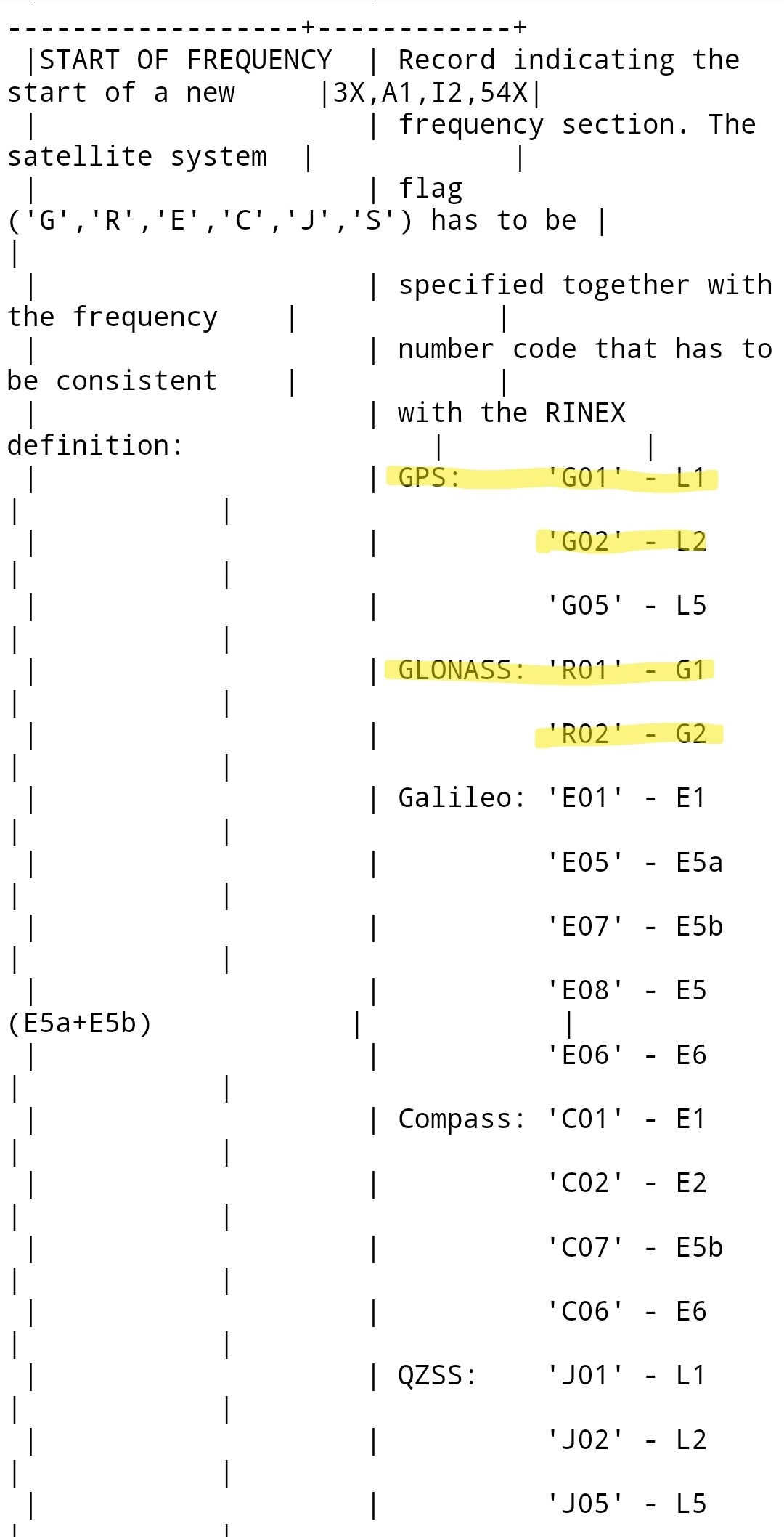
G01 (GPS L1) -0.98 +1.92 +134.92 NORTH / EAST / UP
G02 (GPS L2) -0.44 -0.06 +137.10 NORTH / EAST / UP
R01 (GLONASS L1) -0.98 +1.92 +134.92 NORTH / EAST / UP
R02 (GLONASS L2) -0.44 -0.06 +137.10 NORTH / EAST / UP
Something that I and others have pointed out is that when you do postprocessing in Emlid Studio it doesn’t use the manually entered coordinates from Emlid Flow.
You have to set those values again in Studio, or drag a POS file into the box. For example I correct my base station using a CORS station, and then drag that single position POS into Studio to set the base coordinates.
The problem is most users don’t seem to know this and assume base coordinates are retained from Flow to Studio!!
I think it should be made clear in Studio what is going on and maybe prompt the user to put in coordinates or choose a POS file.
So in the case of base coordinate averaging, do you enter an antenna height of zero?
Hi @daygeckoart,
Thank you for sharing your feedback on this. It’s a good point, and we’ll think about what we can do to make it clearer in the app.
Hi @kdoherty,
Good question. Thank you! Technically, you don’t need the antenna height in this case. You’ll already have the APC coordinates after averaging, so they will be used for calculations in RTK.
However, I still recommend you enter the actual antenna height. This way, the app will calculate the coordinates of the point on the ground. It’ll allow you to use the same point in future surveys and get consistent results.
Thanks for getting back to me. In our case we are mounting an RS2 on the roof of our facility to serve as a permanent base, broadcasting corrections indefinitely. We plan to average position only once, and don’t plan to move the unit after switching it to broadcast over NTRIP. It is not straightforward to me how to estimate height above ground as I cannot access the terrain below the building, or I’m not sure if I should consider the convex hull of the building the ‘ground’.
For my application, what is the best practice for parameterizing antenna height in Emlid Flow? Am I correct in my understanding that setting an arbitrary antenna height of the base won’t influence the quality of corrections the rover will receive?
The elevation sent to the rover will be the elevation given + pole height + 134 mm. So if the elevation on the ground is 90m, and the base of the receiver is 10m above it, then it will give its elevation to the rover as 100.134m.
If you know the elevation at the base of the receiver is 100m and you put in 0 for the pole height, then you also get 100.134 m.
For a permanent base, one way to do it is install it, process with OPUS with a 0 pole height. Enter that elevation in for your base coordinate, and also use 0 pole height in Emlid.
I’m following this thread, and trying to clarify one aspect. If I’m averaging the base position and inadvertently have the antenna height set to 2.00 meters (fixed height tripod), does the data in the exported RINEX file reflect the ground position or the APC position? The RINEX observations file (.24O) does show the antenna height as 2.000000, but I don’t know if the actual data is offset as well. I’m processing the base position with OPUS and using the position delta to correct all rover positions. Thanks for any clarification anyone can provide.
OPUS doesn’t look at that 2.0 in the header. The data won’t change.
Right, demonstrated that to myself. But what does the data represent? APC or ground (calculating the 2m offset)?
The data is APC
Perfect - thanks very much! I had inadvertently (and inappropriately) set the Antenna Height to 2.00, and wanted to make sure that it didn’t skew my averaged position.
Oops, wait a second. Maybe read that too fast and misunderstood. Your base averaged a coordinate and your question is whether the elevation of the averaged coordinate is on the ground or APC?
I guess it’s a double question:
With an antenna height set to 2.00 while Averaging a position,
Ugh, this is confusing!