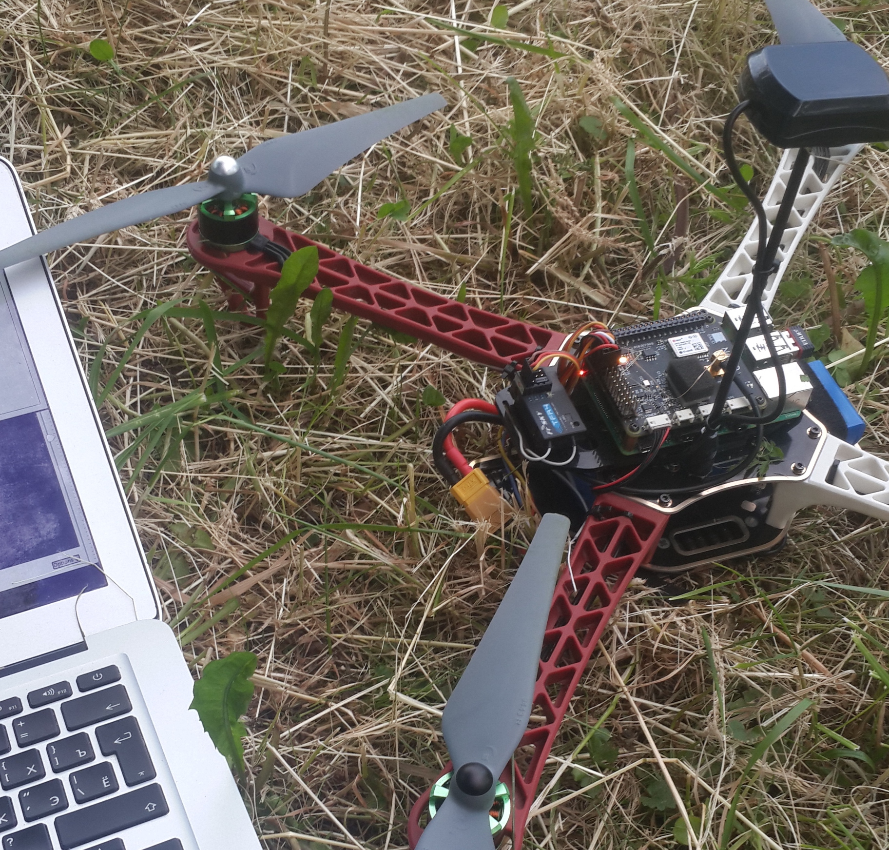
Recently I have assembled a 450mm quad for flight testing Navio+ and APM code. I thought it would be a great idea to share the build with full part list and desription. I hope that this thread will help beginners get in the air faster.
Also a radio and a PPM capable receiver. We will use Futaba T8FG and FRSky TFR4 Rx (about $400), but if you are just starting Taranis ($220) is a very common choice.
Here is a list of what you will need to accomplish this build, feel free correct me as I probably missed something. Also, would be great to see simultaneous builds, so hop on
Next time you get it apart can I see the under side of the top plate (how you mounted it)? I’m just using servo tape for my 550 and it’s a bit sketchy lol
A couple of weeks ago I assembled a F550 hexacopter using Navio+ autopilot and APM firmware. It flew well enough by RC but unfortunately when I tried to use the APM Planner it went completely wrong, It crashed and the main frame got damaged.
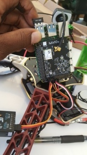
Hi, I’m glad to see that you’re using my NAVIO case design
Can you share some feedback? If you like the design, what you want to see improved, all the feedback are welcome. I’ve made some modifications that I’ll share on thingiverse on next week.
Hi Pedro, this Navio case is awesome! I found it on thingiverse and I totally loved it. The RPi + Navio fits perfectly. I had some troubles when assembling, the upper part didn’t fit on the lower, but probably because of the quality of the 3D printer. I just removed some material and now it fits perfectly!
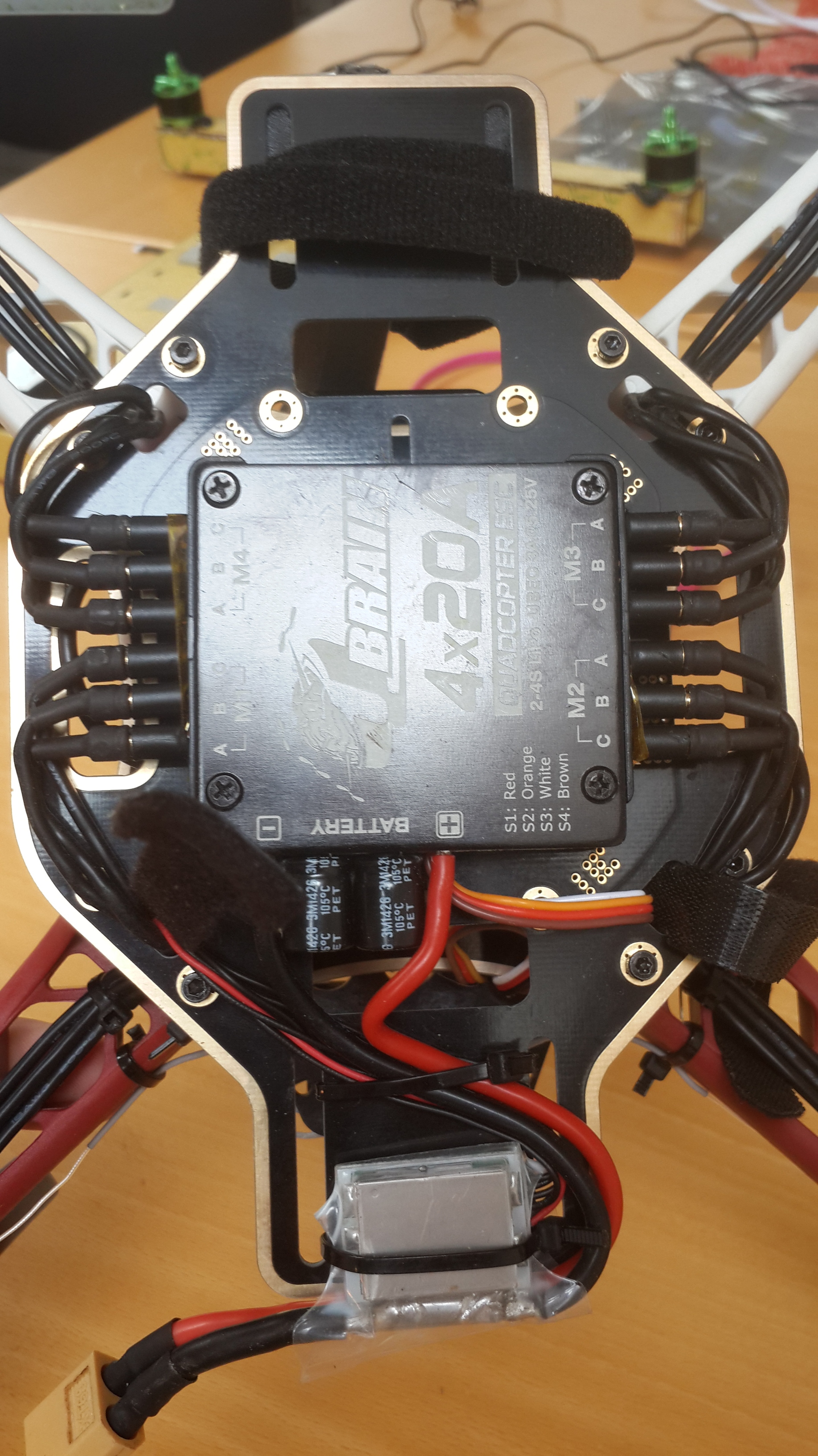
Usually wiring motors to the ESC is fairly straightforward: connect three wires between them, black an red wires go to the battery and servo plug is connected to Navio+ for control.
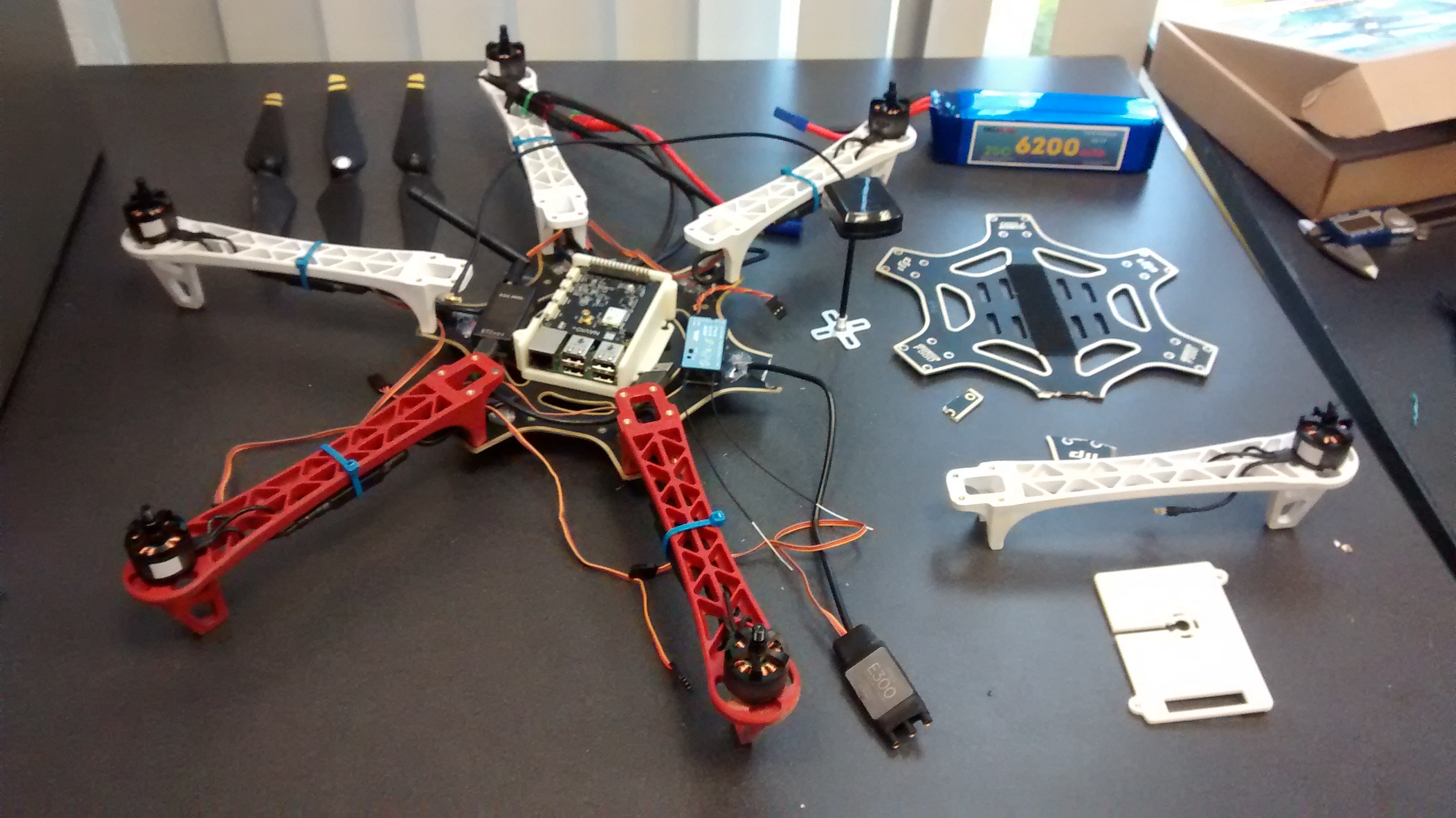
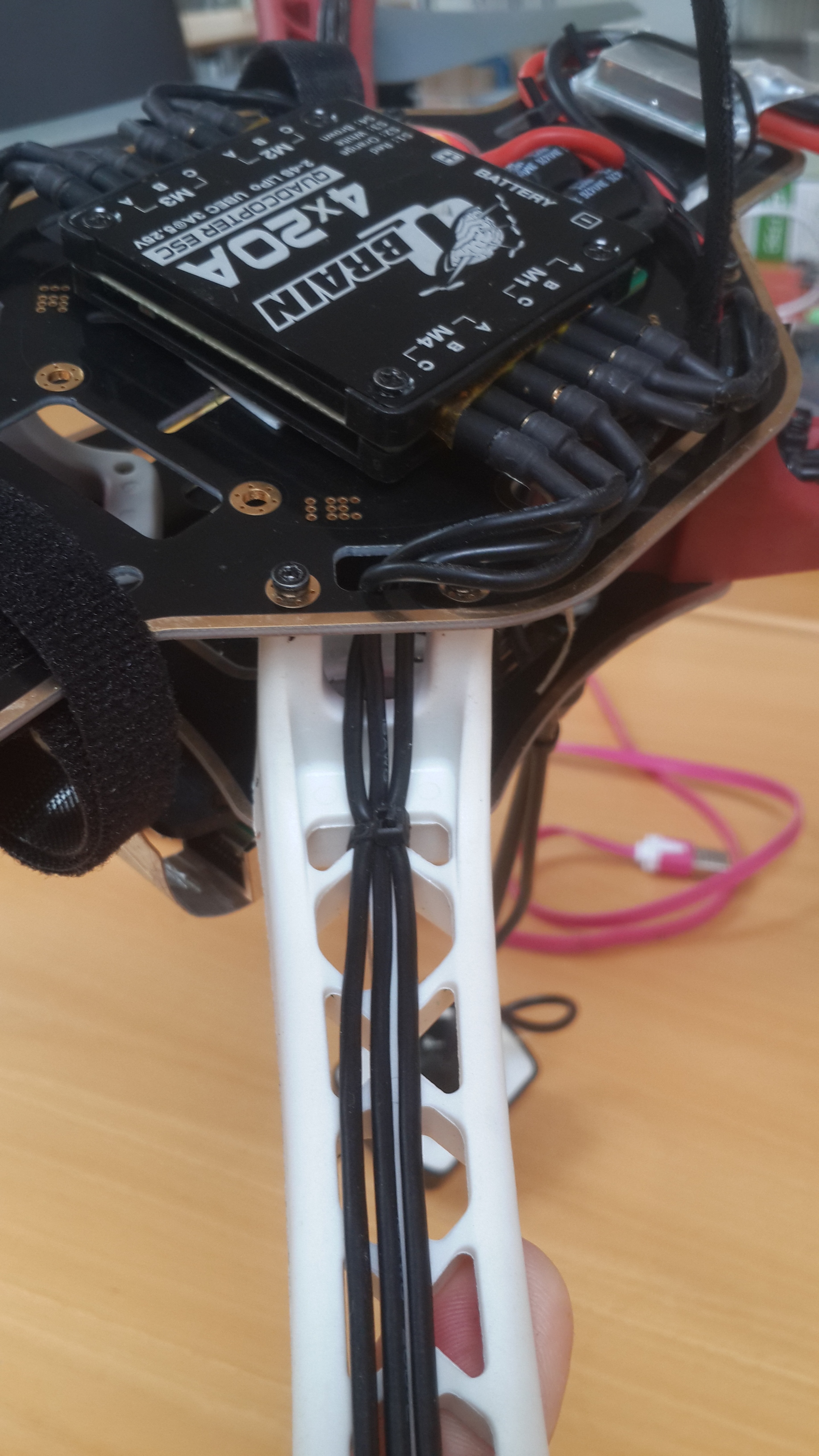
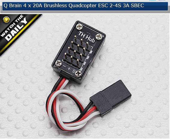
In this project I am using a 4-in-1 Qbrain ESC, which packs 4 ESCs and makes for easier wiring. For a quad it eliminates any need in a PDB (power distribution board).
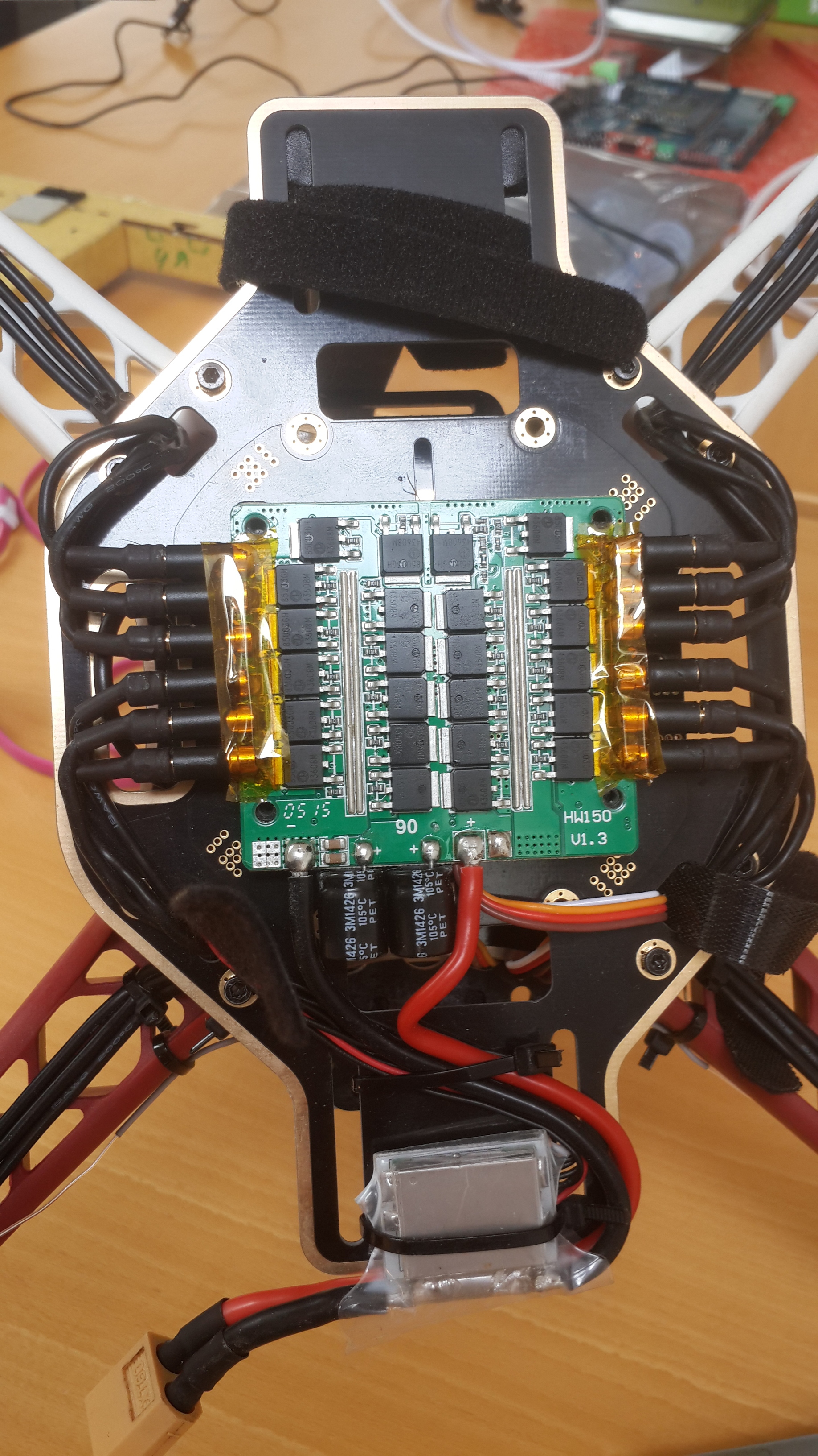
I really enjoy clean wiring and have decided to remove the cables that come with Qbrain. Motors have wires long enough to connect directly to the ESC. After I have desoldered the wires, connectors from them were removed and soldered directly to the PCB. Please note the insulating tape on top of the connectors. It is there to protect them from shorting when putting the ESC lid back.
Power from the battery does not go directly to the ESC, but rather passes through the power module. This will let us see voltage and current values in the GCS.
Here you can see how wires are attached with zip ties to the arms. Make sure that everything is properly fixed and will not fall off in flight.
you will need to add some adhesive to the other side. I use 3M 467MP, its semi permanent and holds up well against heat and vibes. i use this stuff all the time on my builds.
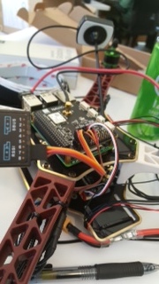
@igor.vereninov I having a little trouble understanding the final connections between the battery, navio+ and the receiver. Some of the connections are obvious, but I am not seeing what the wire from the battery (yellow, red, blue, and black) is connected to. I also don’t quite understand the connection to the receiver and the navio+. You seem to have more wires connected then I have present. I am using the Taranis -plus transmitter and the x8r receiver.
It seems like you are using a 3C battery. Those extra wires from the battery are for balance charging. If your charger supports balance charging, you plug them in to the charger. Mid flight, you will most likely use it for low-voltage alarm. As for the receiver setup, you should only have one set of wire (ground, pwr, signal) coming from the receiver. Guessing by you saying
I think you’re mentioning the ESC control wires connected to the Navio+. Photo of your setup might help.
@jasonyoun thanks. I will give it a try on tomorrow. The photo of the setup just seems to have a lot more wires than I have present. I wire everything tomorrow and send a photo.
On the servo rail the ground pin is at the edge of the board and the signal pin is the innermost. You connected RX and ESCs the wrong way around.
But you will need a SBUS to PPM converter for the x8r receiver. http://www.frsky-rc.com/product/pro.php?pro_id=112
I love this thread! Because of it I went and changed a lot on my own quad, like the frame and esc.
I do have a question though for you. Did you calibrate the Q-brain in anyways? And if so, can you describe the procedure? The instructions say to calibrate it to the controller but do I need to do this with the ESC getting the signals through the Navio+?
Yes, I have performed the calibration. Actually I sequentially plugged each channel into ch3 on the receiver and calibrated them one by one. For me it looked like the fastest way to do it. It is not compulsory to calibrate them through Navio+.
I’ve been having problems with my QBrain. I was able to calibrate it (using the hub) but now when I arm it, it spins pretty fast, and when I give it just a tiny bit of throttle, it acts as if it jumps to full throttle (since I don’t have propellers on it, its hard to tell just how high of throttle it is running at). Right after ESC calibration mode, when the navio is sending the signal straight to the ESC, it works normally.
I used the hub instead of the method robertb mentions because I couldn’t get my Navio to go into ESC calibration mode. When trying to fix this throttle problem, I saw that my navio/apm/mission planner was defaulting to an ESC setting of 0, which means it would never go into ESC calibration mode, even if the throttle was high. I switched that and was able to observe the proper behavior.