


In the previous tip, we discussed the UTM and Gauss-Krüger map projections and their peculiarities.
In this tip, we will consider a transformation grid, another possible component of the coordinate systems used in countries such as Great Britain, Switzerland, Greece, Austria, Poland, Italy, Slovakia, Slovenia, and others. Let’s take a closer look.
What is a transformation grid?
A transformation grid is a component that helps to transform coordinates between different datums and coordinate systems. These grids eliminate variations in the earth’s shape, measurement imperfections, and other factors that simple parametric transformations under the bonnet cannot capture. In other words, the standard “fully invisible to the user” approach doesn’t work here.
Why do we need grid transformations?
As you can see, grid transformations address special cases:
- Your region uses local datums that differ from those used in modern GNSS, and the grid helps to transform them into another.
- You survey in countries that use old geodetic networks with some irregularities, and transformation grids provide correction values for small areas. This helps to ensure more accurate and homogeneous transformation of coordinates over the large areas.
Sounds a bit complicated, doesn’t it? Let’s look at the particular cases when you need to apply horizontal transformation grids.
A bit more about the cases
At this point, we need to step back in time to understand better one of the most common reasons behind grid transformations.
Before the invention of GNSS, surveyors usually relied on geodetic networks that consisted of control points with known coordinates derived from observations that tie the points together. This allowed the surveyors to tie their measurements to the necessary coordinate system.
One of the most popular ways to create them was the triangulation method. This method involved measuring the angles in a triangle formed by three control points. The coordinates of these points were calculated using trigonometry based on the known coordinates of one point and the length of an adjacent side. All of this work resulted in a network of triangles that provided a set of control points for surveying.
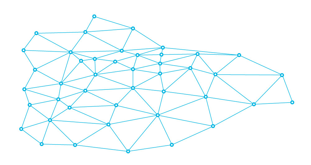
Geodetic network
With the advent of survey-grade GNSS, it turned out that the coordinates of known points collected by GNSS sometimes did not match the expected coordinates. The errors occurred because of imperfections in the coordinate transformation from the global datum used by GNSS to a local datum used in that country.
Another reason for the mismatch was that some old geodetic networks had irregularly distributed imperfections that affect the final result.
The cases may vary, but the truth is that to resolve such coordinate mismatches, you can’t simply apply universal formulas or a set of parameters that can ensure accurate transformation for the area of the whole country. The differences between the coordinates are not homogeneous.
How do grid transformations work?
To make GNSS coordinates match the expected X and Y in the local coordinate system, you must add an individual correction to each point during the coordinate transformation.
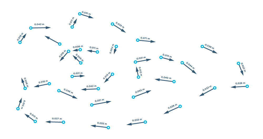
Such corrections result in transformation grids. They consist of a regular network of points with known correction values that adjust coordinates from one datum or coordinate system to another. Extensive geodetic measurements and observations served as a basis for these grids.
When transforming coordinates, the software interpolates the correction values from the grid points to the location of the transformed coordinates. To get an idea of the interpolation process involved, let’s switch to Emlid Flow.
How do grid transformations work in Emlid Flow?
In the Emlid Flow app, the grids are raster data consisting of equally sized rectangular pixels. The pixels are arranged in rows and columns. Each pixel carries correction values.
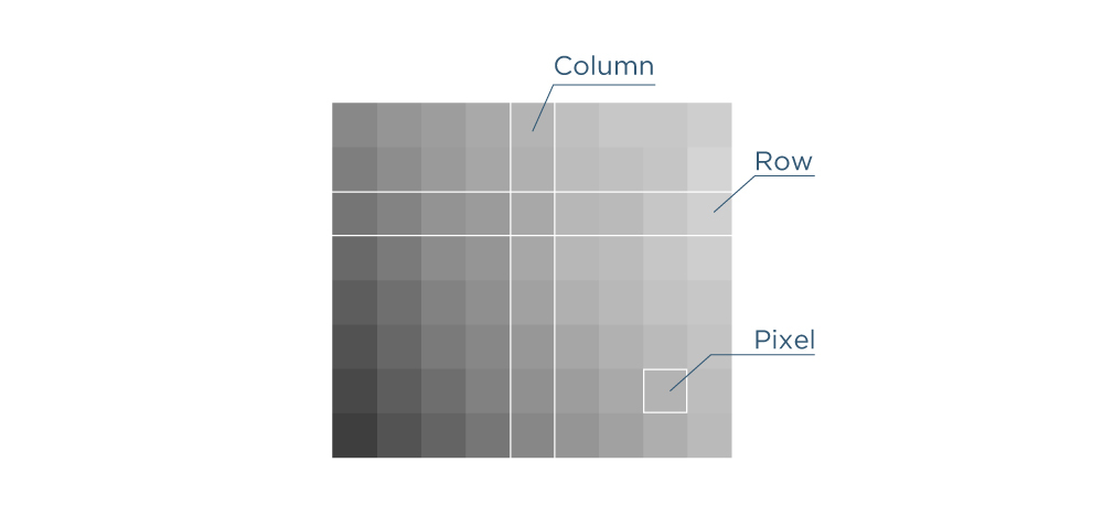
How does this help us in practice? When you collect a point during surveying, it “falls” into a certain area of the transformation grid. The software then uses the information from the closest four pixels for transformation, resulting in the coordinates of a point (X,Y). This process is known as interpolation.
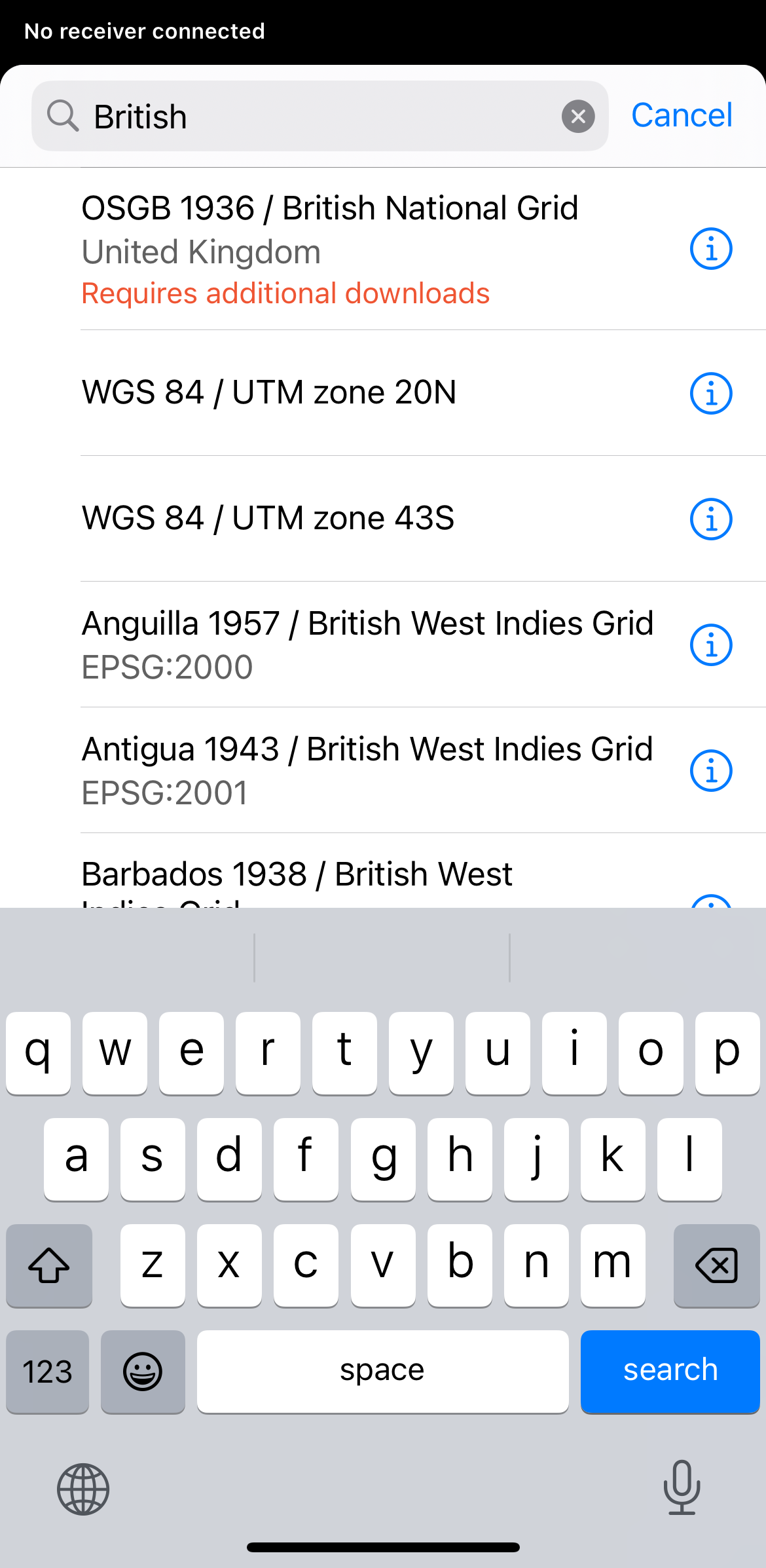
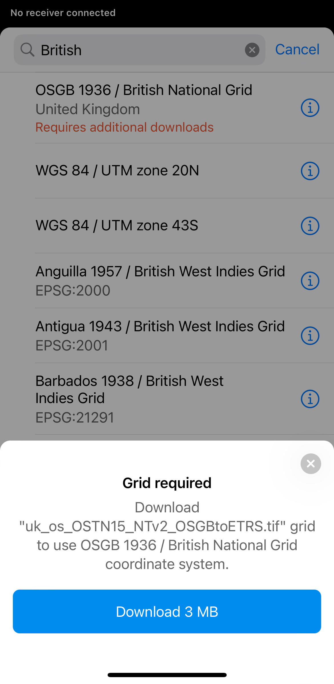
The library in Emlid Flow contains many coordinate systems that require a grid for accurate transformation. When you select one of these systems from the library, the app will offer you to download the transformation grid TIF file.
If you have any questions or need help setting up the correct coordinate system, comment below or contact us at support@emlid.com.
In the next tip, we will continue talking about transformations used to switch between different datums and coordinate systems.