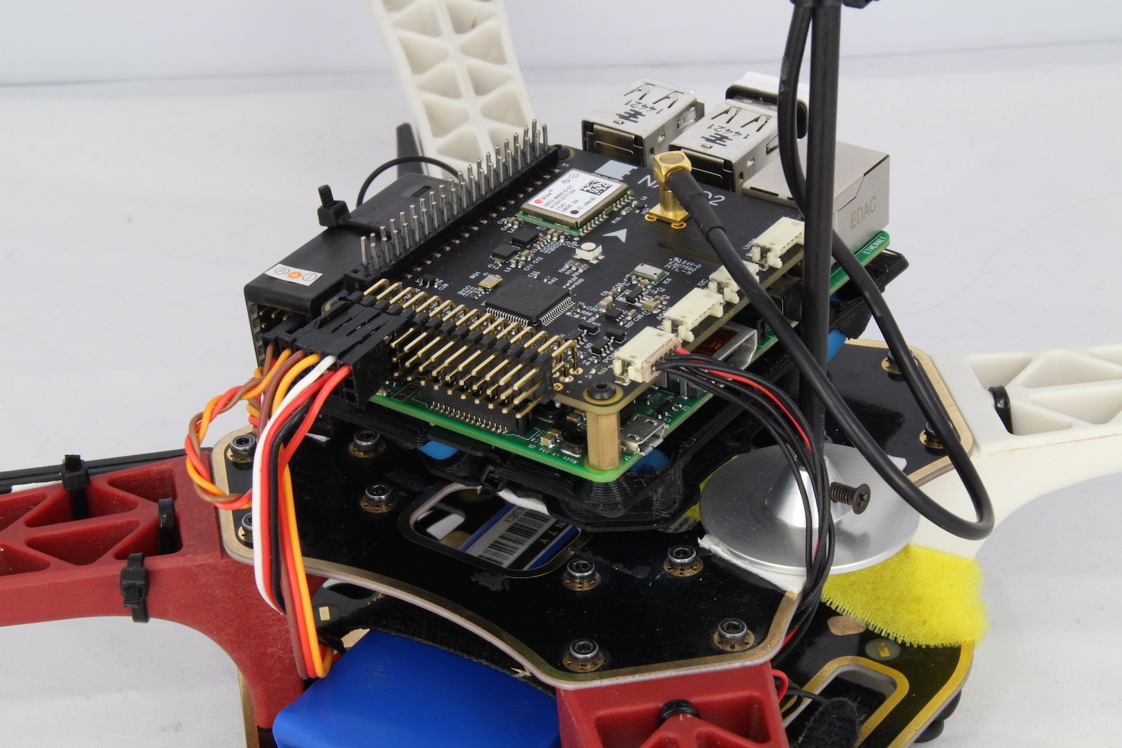
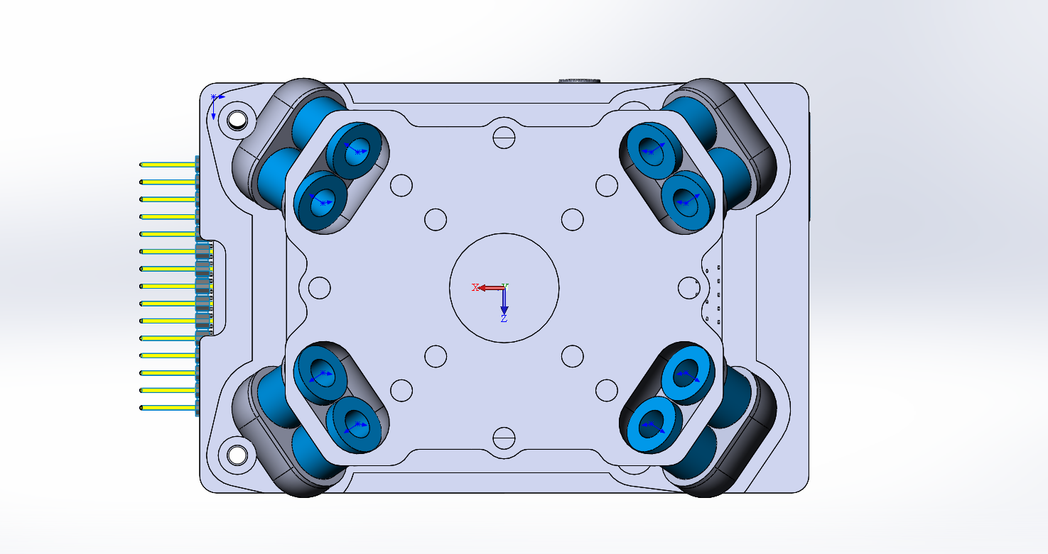
We have designed an anti-vibration for Navio that can be easily 3D printed! It significantly simplifies mounting and eliminates vibrations. It is suitable both for Navio+ and Navio2.
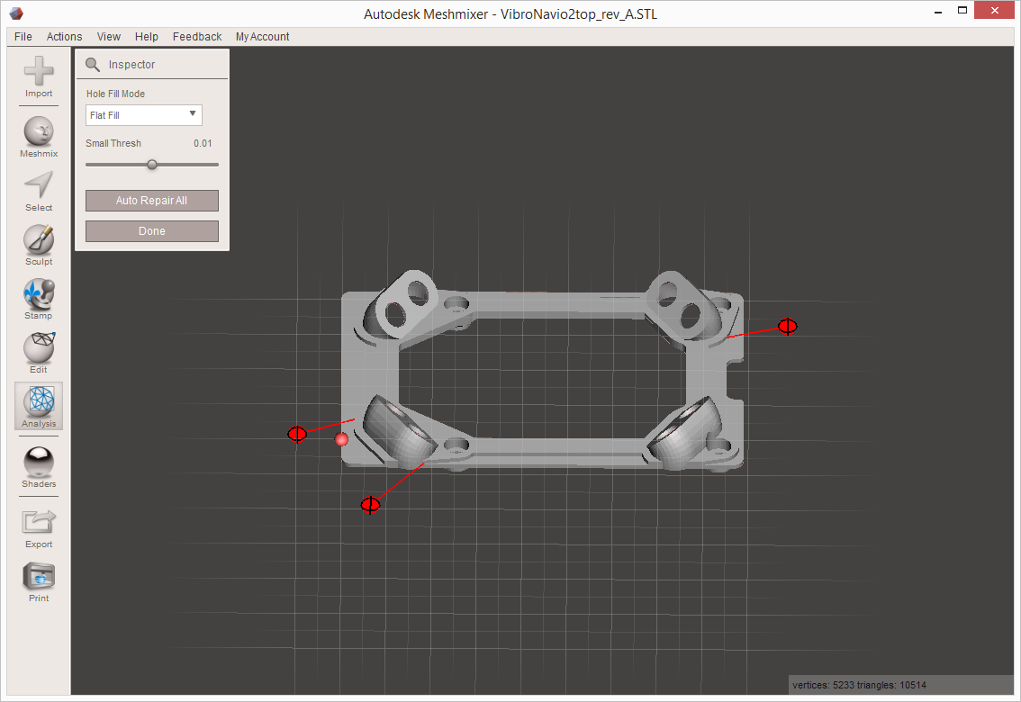
Before a print, I always verify/inspect the STL to make sure it is a solid mesh (no holes) so that there will not be any issues when printing. Most 3D software will let you do this, eg MeshMixer, Netfabb, Rhino, etc.
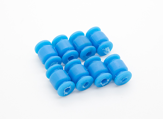
Could you please make a screenshot of the issue? I mean there are supposed to be holes in some places, maybe the cavity for the dampening balls is suspicious?
Screenshot in MeshMixer showing the 3 areas that are bad, I have not done a detailed analysis using other programs yet, but this should give you enough to carry out your fix.
That’s perfect I was about to do the same. I was able to hang Navio off the top of the APM anti-vibe plate but this one is much better.
Some variants I’m considering building are with the top of this plate merged to the bottom of a 3D printed Navio case to get a direct case to frame mount. Or the same with detachable (screw/cable-tie) points.
About the solid thing that is an artefact of 3D editing software. Something which can be introduced during grouping and export. Depending on which software you used to make it, there are ways to fix easily, but it’s much easier to do with the original 3D design files than patching the exported STL.
For example in Sketch-Up the fix is to install the solid tools analyzer and use it’s wizard to identify the weak links, e.g. lines which are fractions too short. The other way is to click on each face and check that there are minimal cross-sections/triangles, then erase them to force the 3D designer to re-calculate as one solid face (or totally destroy it so you know you have to re-create because it was too far off straight). Of course 3D objects are rendered with triangles but the object in the editor should have as few points as possible.
When it is not solid usually one of the additional points/lines is a fraction too high/low or not properly “grouped”, so the 3D slicer software thinks it’s a case with a crack in the middle, not a solid.
After much pain with “free” tools like SketchUp (which turns out not to be free in the end because solid tools are not included for free = useless for good 3D print design) I switched to TinkerCAD (or you can even use AutoDesk’s bigger Fusion 360 variant as a hobbyist). Not only does that work much more simply with easy graphics and UI like SketchUp (in my opinion better) but it directly pushes the user towards working with 3D printer friendly solids and has a unique idea about simply changing the material of objects/groups from a colour to “hole” in end effect making additions and subtractions (equivalent to “professional” solid tools in SketchUp) and really works for free!
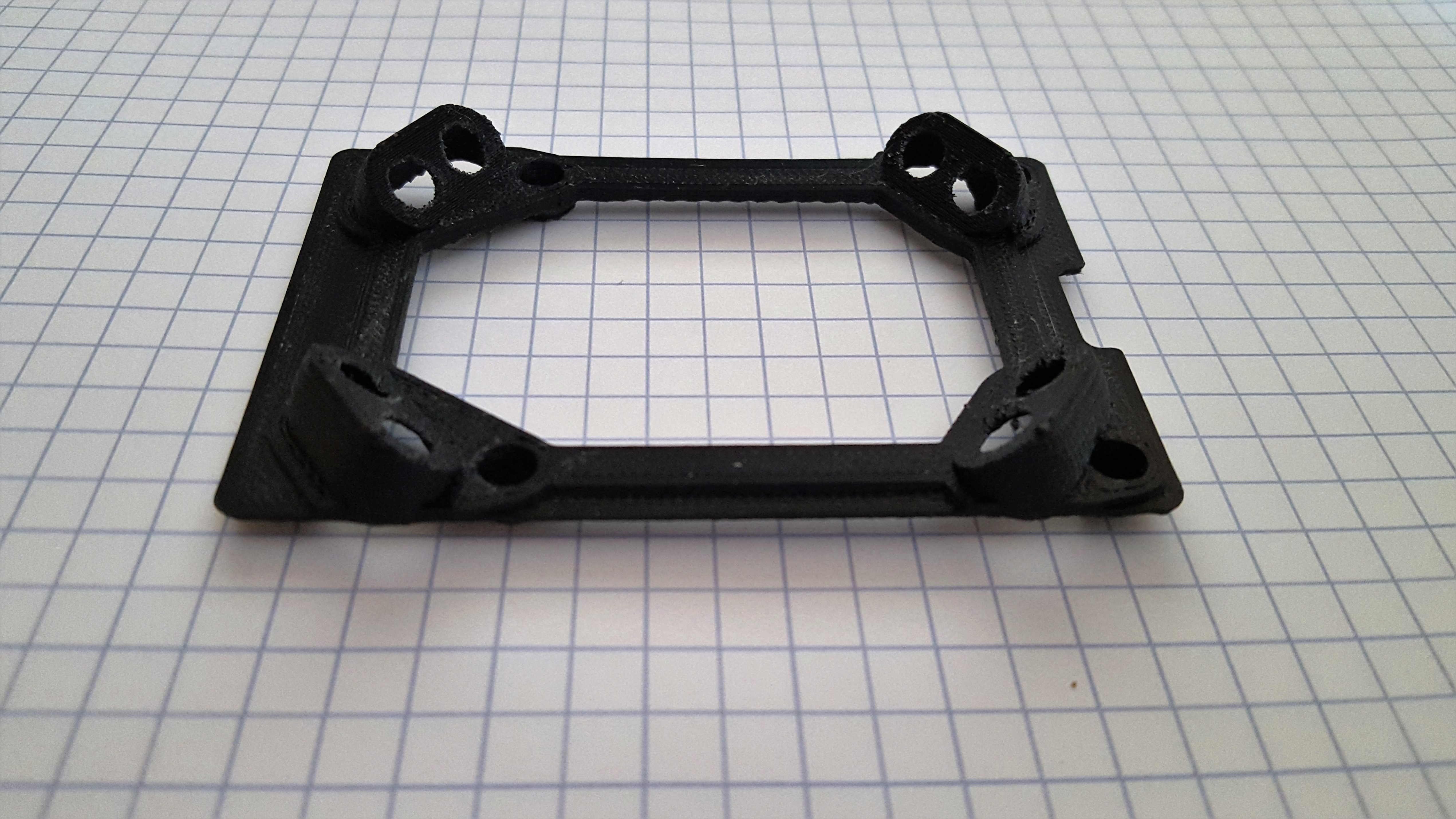
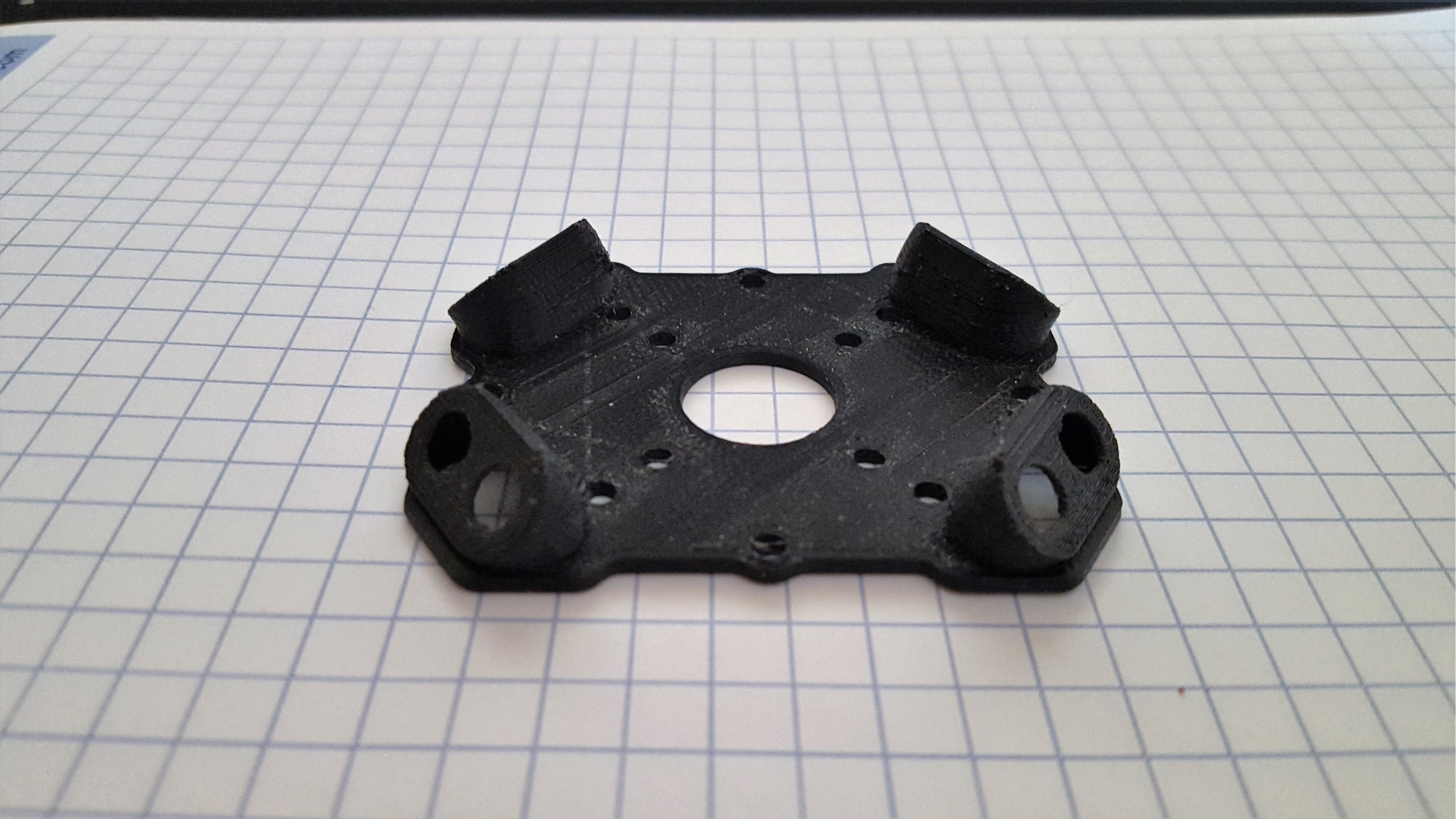
I’ve a question about the 3d printing of the top piece. It has significant overhangs - due to the way the holes for the bolts protrude.
How have you printed to avoid this - with heaps of supports? Won’t this produce a rather rough print? Assuming you are using supports, which slicer do you use?
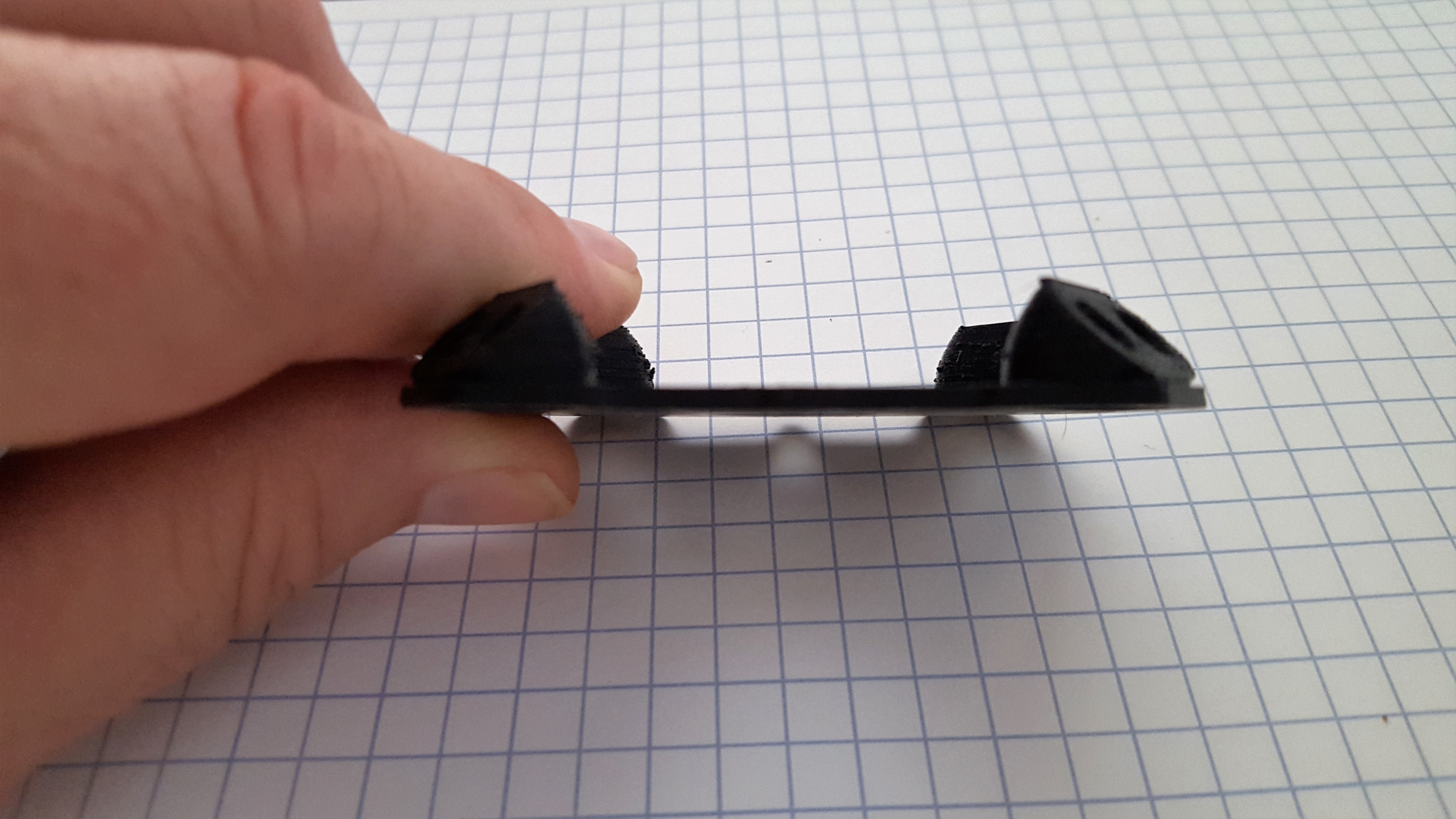
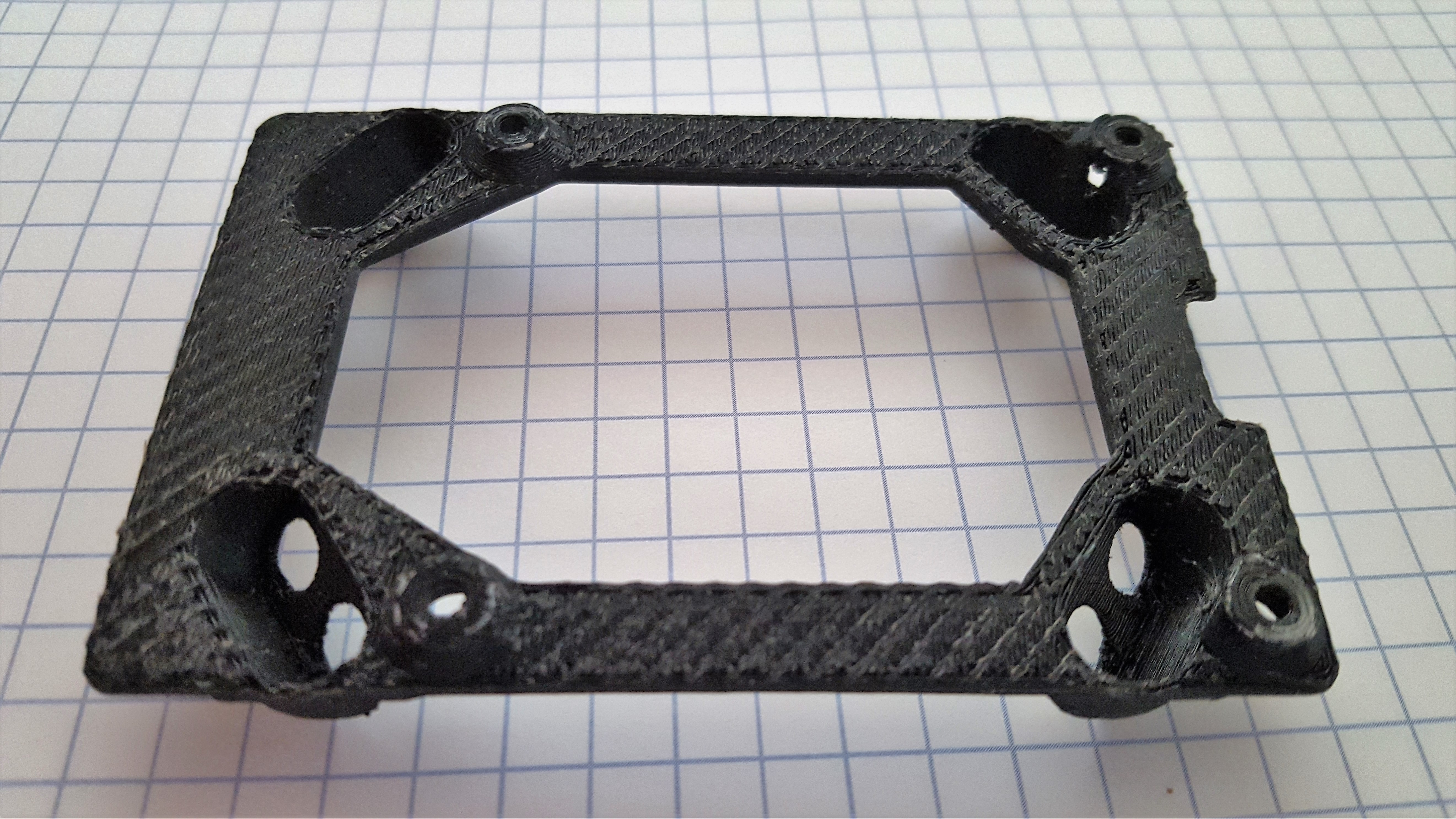
Thanks for those pics - the underside of the ‘top’ part was the bit I was interested in,especially the impact of the supports.
Structurally I suppose it makes no difference, as it’s not in contact with anything.
Ditto here, either will do. If printing one of the cases though they won’t really work together unless you do a bit of drilling and get some longer screws. Something to bear in mind.