


Wow. So you didn’t even have to localize to a known benchmark (set up manually on it with known coords and height)? Just used NTRIP? Was it to a state CORS nearby?
1 Like
Thanks, Yes just used NTRIP. The NTRIP here is very good! It’s the Las Vegas Vally water districts network. You have to sign up with the water district and get an account with them.
1 Like
This is all I know and ever used, Just here in Vegas, When I first got the RS2 . I downloaded a list of known mount points in my area. I went to those points and pulled my own points and most were dead on with what the paperwork said the mt points were. And only sat on points 2 mins after fix.
2 Likes
Doesn’t get any easier than that.
1 Like
I am not fully familiar with drone work… yet… but is the screen shot a DroneDeploy app or something? How did you overlay the civil drawing? AutoCAD CIVIL/MAP, dxf, dgn file? Did it come in to exact scale and location (i.e NAD83 coordinate system?)
2 Likes
My workflow was posed as a question for verification, that’s how I understand it anyway.
I have only been playing GNSS fence builder for a little bit. I am just trying to get the most accuracy out of this system in both WGS84 and NAD3. If you really know what you are doing RS2 is extremely accurate.
2 Likes
In my experience a 30 minute average will usually get us within 1m XY and 1.5m Z of absolute position, but with RTK to the rover you get the same cm-level relative accuracy which means that you can always come back and shift all your points to absolute accuracy if needed.
We can actually work quite well this way in construction because we have local vertical benchmarks to adjust to and can do the horizontal shift in CAD. We have been using NTRIP for about 6 months now and even though our previous workflows with localizations were easy it has been money well spent to know that we are on every time within a few minutes of getting out of the truck and not having to set up a base. Running the drone off the same NTRIP is even more of a pleasure.
4 Likes
We use DroneDeploy as well and that is a PDF overlay either from a plan sheet or a CAD print. The overlays require manual alignment the first time but as long as the data alignment persists with subsequent maps it will persist as well. If you export the data from DroneDeploy in your CAD coordinate system and bring it into CAD then it does automatically align. This is where it is absolutely important to either have a cad file that is on state plane or use GCP’s. The former is unlikely so GCP’s are a must.
3 Likes
I am posting this across the different forums independently to see what kind of insight I get and is primarily in DroneDeploy but to me it seems a little relevant to what we are researching here as well.
I have started seeing some weird numbers with the H520E RTK imagery now. If I process the map without any ground control my camera GPS location RMSE’s are right around 1ft XY and 0.4ft Z but when I introduce GCP’s the number as all over the place and more up around the 1m range across the board with the vertical being slightly less for the most part.
My rationality for this is that our drone and running on the same RTKNET via NTRIP which broadcasts NAD83(2011) coordinates. The rover has data collector software which use NAD83 natively and projects it to our local State Plane Coordinate System which the values in the GCP file are based on. The drone on the other hand works in WGS84 but I don’t know exactly how it negotiates the NAD83 corrections. WGS84 and NAD83 are very close in some areas and not so in others spread across the United States but we have to keep in mind that not only are there difference in the horizontal reference frame but they use different ellipsoids as well. WGS84 has its own and NAD83(2011) uses the GRS80(2010.00) ellipsoid. Factor on top of that which GEOID you are using and there is the additional split in vertical. Because we are localized to the site benchmarks our checkpoints come out fine in DroneDeploy but the data always has to be given a final alignment in CAD.
1 Like
@michaelL When you sample the resulting point cloud, in the dataset without GCPs, at a spot that you can measure on the ground, does it match reality or not?
It matches reality according to NTRIP which most commonly does not match site level-looped benchmarks within our accepted tolerance of +/- 0.08ft (2.5cm). These LL-BMs are quite often 2nd, 3rd or even 4th generation from NGS for the most part but error occurs in every loop. At least that’s my explanation. This is the vertical aspect of construction that is done in the Topcon software during localization but Reachview does not have that capability so we play middle-man by shooting native and finalizing in processing vertically via the localized elevations and horizontally in CAD. Whether or not the horizontal matches within tolerance directly from photogrammetry to CAD is entirely dependent on the position of the CAD linework and the condition of the actual control on the ground.
Drone Deploy Software has the ability to overlay drawings, either PDF and manually overlay (like the one above) But you can also upload geo-referenced drawings into Drone Deploy as well. If you can get them.
1 Like
Is the 2023.8 ft height shown in DroneDeploy ORTHOMETRIC? Based on the NAV88 vert height directly from what you set up in ReachView3 (RV3)? Wonder what GEOID RV3 uses in connection with NAV88? i.e. GEOID12, GEOID18? Do you know what the ellipsoidal height was for this LatLong point is in DroneDeploy? Just curious, as I was getting orthometric / geoid heights different than what your showing for that LatLong point. I’ll have to double check…but missing the ellipsoidal height to check.
I assume the 2023.81 manhole rim height of the drawing is also ORTHOMETRIC height? Does the Vegas NTRIP service state which vertical datum / geoid heights are based off of… which I assume is also NAV88? and possibly a particular GEOID? i.e. GEOID12, GEOID18?
Thanks, just still learning about these details for vertical height!
Yes, the 2023.8ft is from the drone deploy ortho map, using the drone geo-tagged phots combined with the GCPs pulled with RS2 in 6521 NAD 88 and 6360 NAVD 88. The overlay has no effect on the software. In las vegas just using the drone’s WGS84 ellipsoid height there is about a 60’ difference. (lower). The civil overlay is completely independent of the ortho.
According to the Las Vegas water district, their system will adapt to work in any coordinate system. I do know they use LEICA for their mount points around the valley.
2 Likes
I give you another example. And share a view only map. The man hole rims in the civil drawing are called out to be a set height, but in real life that don’t men they are that exact height.
1 Like
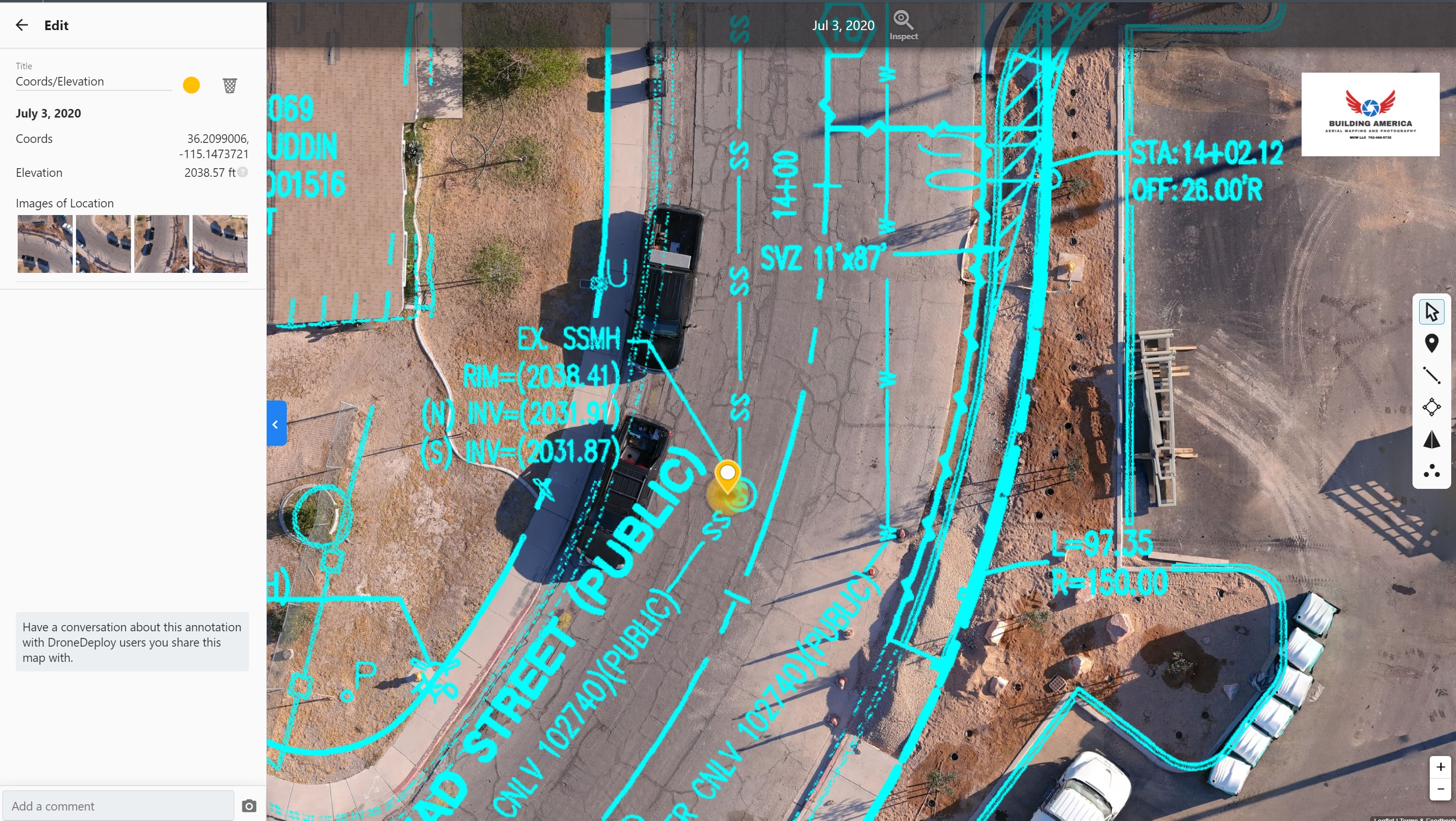
I see what you mean, DESIGN versus AS-BUILT.
1 Like
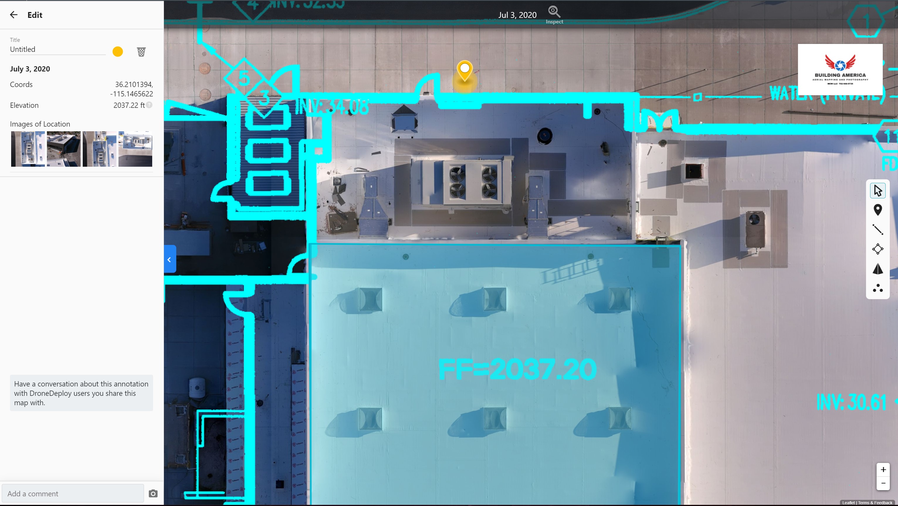
FF Elevation of this building is supposed to be 2037.20. My point in yellow is right outside and I remember there was no step up to go inside, flat. I will measure the slope on that sidewalk next.
2 Likes
Hi there,
Thank you for the discussion!
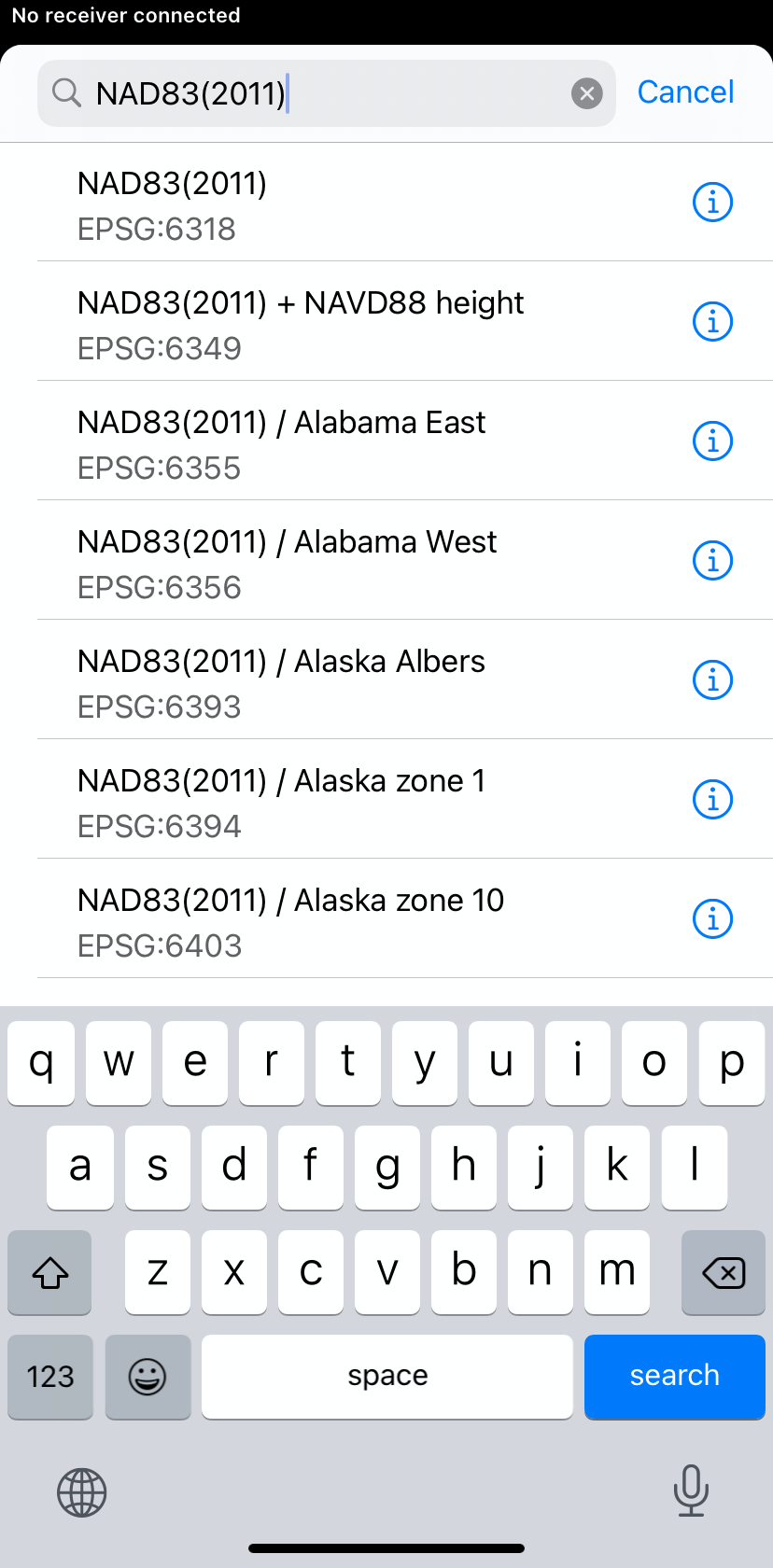
I’d like to point out that Reach requires base coordinates in geographic coordinates, not WGS84 exactly.
NAD83(2011) provides geographic coordinates as well. So, you can put these coordinates in the Base mode Manual input.
Another thing is height. Reach indeed require ellipsoidal height for base coordinates. So, you need to convert orthometric NAVD88 height to the ellipsoidal one above GRS 1980 (since NAD83(2011) is based on this spheroid).
Once you have NAVD83(2011) coordinates and ellipsoidal height in the Base mode, you can create a project in NAVD83(2011) + NAVD88 in ReachView 3 and collect GCPs in the required coordinate system:
Please let me know if something isn’t clear enough. I’ll be glad to help you with that.
9 Likes