I have been working on getting the Reach RTK onto a Phantom4.
The Phantom4, it turns out, is quite an electrically (read RF) noisy platform, but now that the reach unit is adequately shielded and optimally placed I am happy to report excellent results with 100% FIX solutions for aerial missions and remarkable accuracy. I have built a timing mechanism that allows reach events to be created every time a picture is taken and developed the Python scripts to put the reach data into the exif headers. This allows the images to be then processed in your preferred SFM/photogrammetry software.
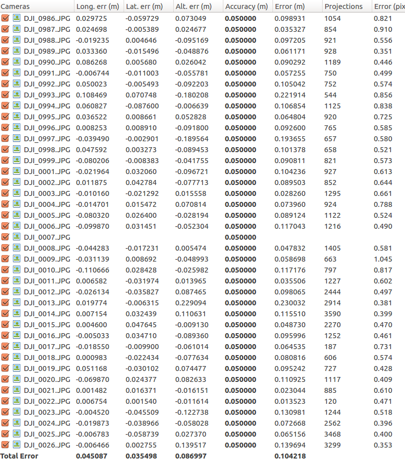
Please see below the error assessment generated by Photoscan for a recent mission. I used a fixed camera calibration so I could not ‘absorb’ any errors. If I let the camera self calibrate I get 8cm error (donw from 10.4), but its distribution is wrong. ie, vertical error is less than horizontal error,
Notice the X&Y errors are both below 5cm and the vertical error approximately 2x that. Any pointers on which photogrammetry software can best utilise the improved accuracy would be appreciated.
Image 7 was a ground shot used to check the altitude, so had no features that could be used in the sfm solution.
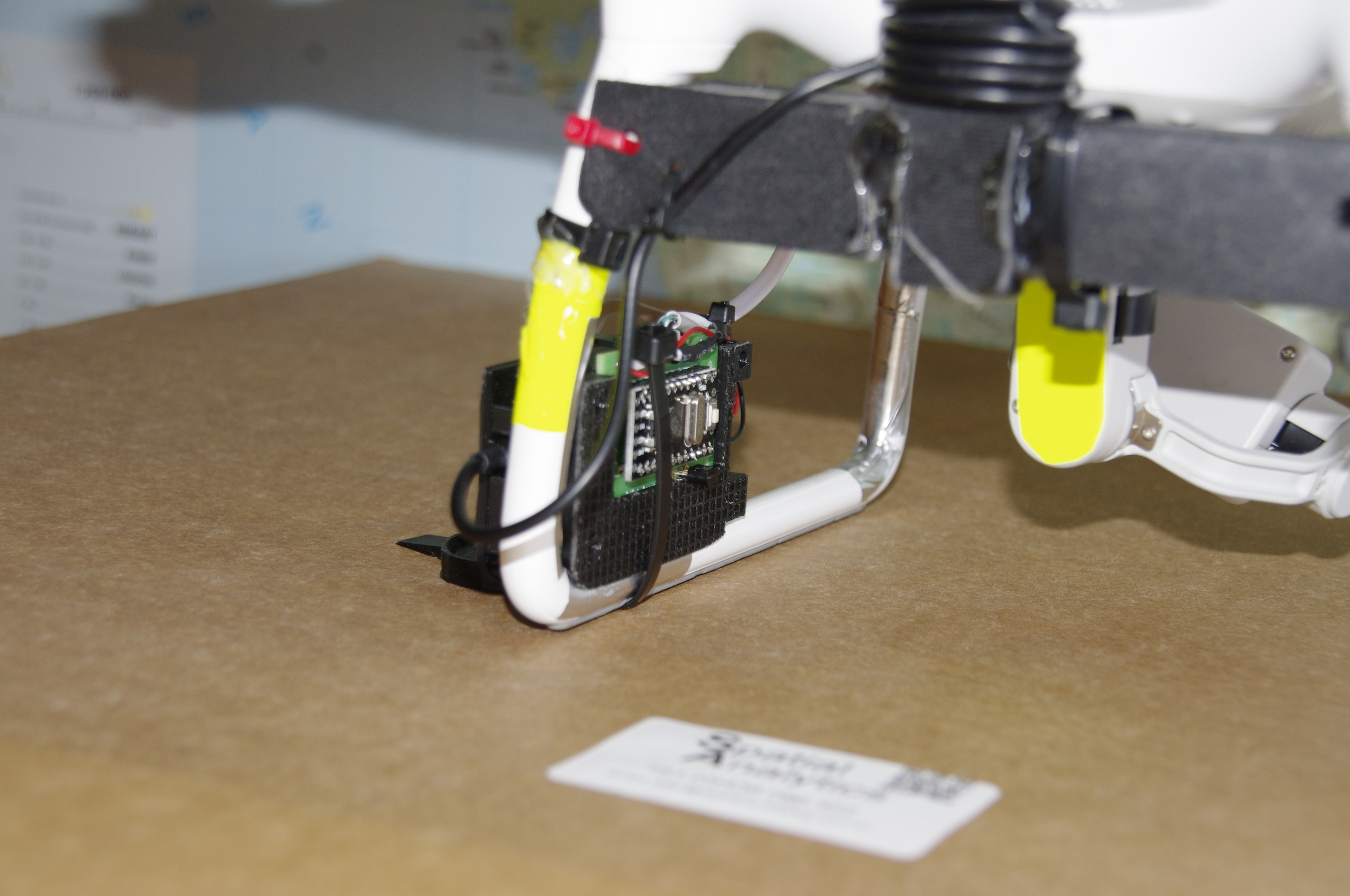
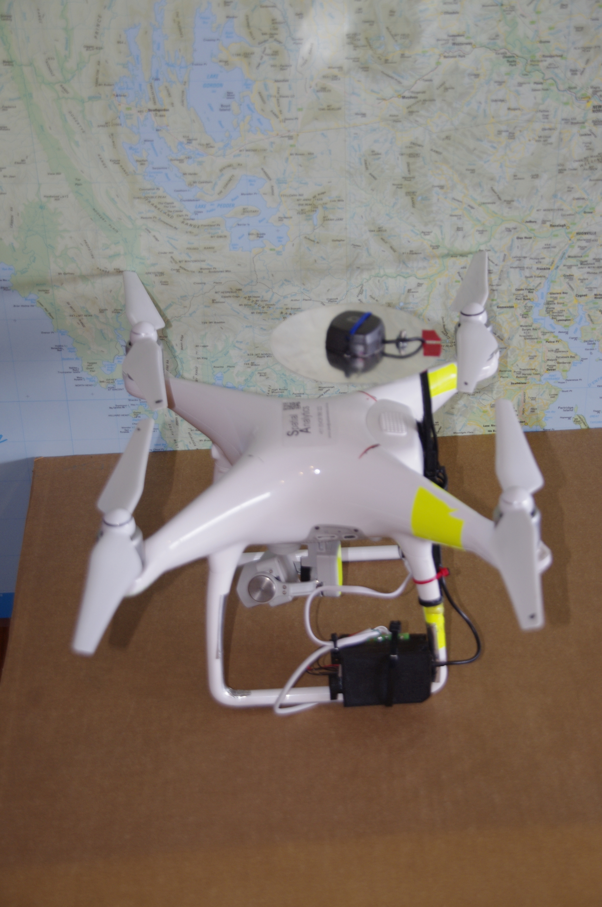
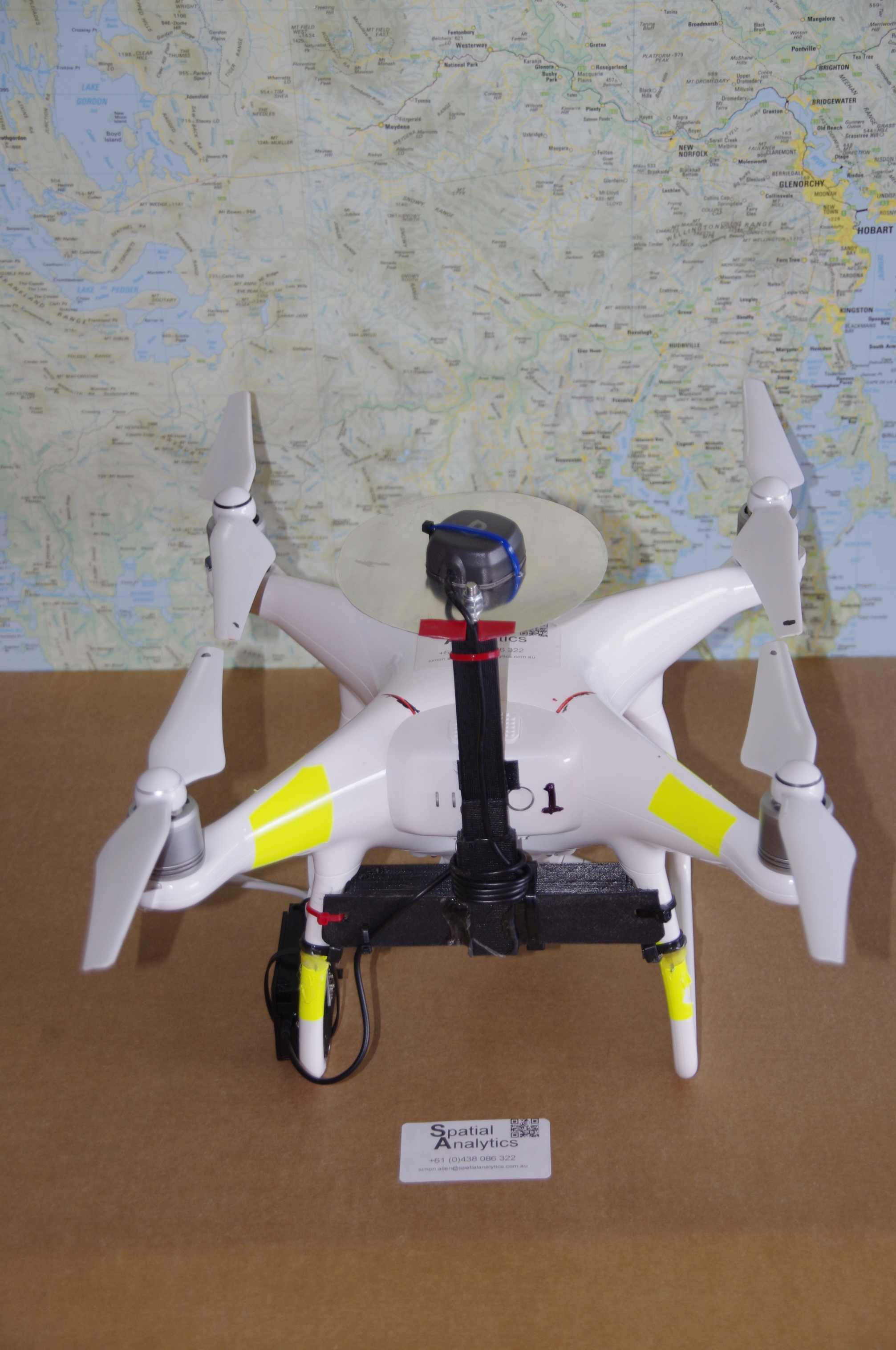
As requested, pictures.
The little black box. fully encloses the reach and is aluminium tape lined. Note the aluminium tape on the insides of the two left legs. I will take any shielding I can get!
Originally the reach was mounted on the antenna frame, but it fits rather neatly in the leg.
Power pack is a single 18650 (2200MAH) battery which powers reach and arduino. This is tucked away in the angle of the antenna bracket.
Arduino takes the trigger signal available debounces it and delivers it to the Reach. OPtions to deliver the sync to other cameras.
@Sylvain_POULAIN
The P4 GPS is below and slightly forward of the groundplane. Yes there is some shielding, but it does a good enough job of getting a fix. Normally 10-14 satellites.
@Matthew_Cunningham
Thanks. I have processed the data through Photoscan, Photomodeller UAS, Zephyr 3D, MapsMadeEasy, DroneDeploy, and Pix4D and ODM.
Currently I favour MapsMadeEasy for delivery to a non technical client, Photoscan ('cos I have a license) because it uses the GPU well and am quite excited by the progress with ODM/WebODM for delivering a robust open source solution.
Once the GPS data in the headers is replaced with the RTK position any processing workflow will produce a reasonably tight orthomosaic.
I have had problems with absolute orthomosaic positioning (ReachView v2.9.3 - RTK performance boost - #62 by Simon_Allen) due to differences in understanding of what the base position averaging does and where it is used. This is now resolved for me and mitigated procedurally. BUT I think this issue is still likely to cause a lot of people to produce different (and less absolutely accurate) results in post processing than they collected in realtime in the field.
The simple answer is yes.
But at those speeds the image blur could be a problem.
So I will not say yes until I have tested (and proven it)
Will be next week (in nice weather with good strong sunlight (which unfortunately means strong shadows) before I can do this.
WHat kind of surveys do you conduct at 15m/s and for what kind of data products/quality?
We did many projects ranging from 50ha to 500 ha with Map Pilot which showed us the speed of 10m/s - 15m/s. The image quality and the orthomosaic quality were good.
No it was PPK, I can do RTK (with 3DR radios), but as you have to process the data to get the events, there is no benefit.
I set up the base as a wifi hotspot, linkk the rover to that get corrections (for RTK) at the start and ensure I have a good fix before fling away and losing the short range link.
You can attach it wherever you wish, the autopilot is pretty robust., But, when flying forward the drone is expecting to tilt forwards, so it easily compensates for the weight of the battery. The second trick is to leave all the obstacle avoidance sensors in the clear. It costs me a single tie-wrap to change the battery. I can cope with that.
I have seen other solutions where a pole and antenna are strapped, taped, tiewrapped to the side of the drone. and a lovely pretty one where a cap and stalk (very organic) are taped to the top of the dome (covering a little of the DJI GNSS antenna, but only in plastic) Of course you still need to capture the timing.
I guess I’m a little confused as to PPK and RTK. You say you are sending corrections from your base to the rover via wifi hotspot? What corrections? What is the advantages to that? Are you gathering data for a known location for your base station?
When I go to a new location, I set up the base for 30mins getting corrections via CORs. I then turn off input corrections from CORs, and then enter the gathered/averaged coordinates manually, and then send base corrections via 3dr radios to my rover. I thought this was considered PPK? Maybe I’m wrong?