I just used the Flow app to measure some points with the RS2. I didn’t use a pole, so my antenna height was 0m (I placed the RS2 on the ground). I figured the height was a bit off so I checked it on a control point.
If I input AH=0, there is no correction for the 0.134m L1 offset anymore (this worked fine in RV3!). The exported csv does contain the 0.134m antenna height, but my measured point is 0.134m too high.
When I use a pole (2m), it DOES correct for L1 offset. The exported csv mentions 2.134m.
See screenshot below, the actual height of the point is 6.530m, which is exactly 0.134m lower than what POSCHECK says.
Have you done several measurements with the RS2 on the ground ? Analysing such repeated data would help to determine if it is an app error as you suggest or a RTK engine inaccuracy.
It’s a curious case, so I’ve tried to reproduce it. However, it can’t be reproduced. I’ve measured the same point three times with different antenna heights (2.0, 1.0, 0.0 m) and the decimal part of elevation stays almost the same in all cases. You can see it in the screenshot below:
Thank you for the investigation. I also tried to replicate it this morning.
I’ll share the csv file with the measured points privately, but the antenna height doesn’t seem to be the issue indeed.
I used two NTRIP providers of which one makes a VRS near the rover based on a few nearby reference stations. When this NTRIP profile is selected when the Emlid is booted, I think the very first GGA string is sent over to the NTRIP provider to be used as a position for VRS. That resulted in a reference station 200 meters below me. I’m not sure if this is an Emlid-thing or should be discussed with the NTRIP provider.
Yesterday I sent the data to support@emlid.com. I think the height difference with different antenna heights was just a coincidence (also a coincidence that the difference was in the order of the PCO of 13.4cm).
With a non-VRS reference, the positions are correct, but with the VRS there are some strange outliers. Errors of >5cm occur in horizonal and vertical direction (however mostly vertical). With a measurement period of 30seconds I think these are pretty high.
Please have a look at the data I sent you. There I measured the same benchmark with different antenna heights, two different RS2 systems and the two different NTRIP providers (VRS and non-VRS).
Why in the world would you set a +$2k instrument on the ground. Boy if I caught one of my employees doing this he’d be fired on the spot.
You can afford the instrument, why not a $200 bipod. This is just one of the most insane things I ever heard of. Oh… maybe you’re just an employee and don’t know how to take proper care of instruments.
You can check your issues on a passive control mark or have someone else provide you one with the data.
This place just amazes me with the amateurs on this site.
Hello, I think I know what’s happening. The software automatically adds in the APC for the RS2 (At least that is what appears to be the case above). Its simple to fix. Remove this automatic add in of Phase center, It will also assist in less programming for future generations of the Reach. Remove the APC addition from the software, and place it as a separate location that needs to be entered manually, for any and all antennas!!!. If this fellow uses the following work around he might get an accurate measurement.
Enter the rod height as a negative APC… OR -0.134.
is for Emlid Change the software, it can even be defaulted to the RS2, or there can be a drop down list of your products, with an option for manual entry as well. This way The software stays viable for future hardware, other hardware, and the M2 as there are a plethora of different antennas you can use with that unit.
Let me know when you guys want to hire me as a product tester
Still, I believe that the APC offset’s automatic consideration facilitates the user experience. You don’t have to think about whether you added the offset or not: you always measure the height to ARP, and the software does the rest. It’s a pretty simple software interaction logic.
As far as I know, it works similarly in other software products. But we don’t suggest the user choose the antenna model: Emlid Flow does it itself. And the manual input option is available for Reach M+ and Reach M2 which don’t have built-in antennas.
I guess I learned something today! Here I was thinking I could not enter the APC for the M2, I just need to look a bit closer at the documentation and software itself. Thank you! Now I can enter the information for my Tallysman into the app!
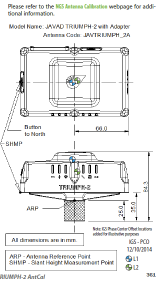
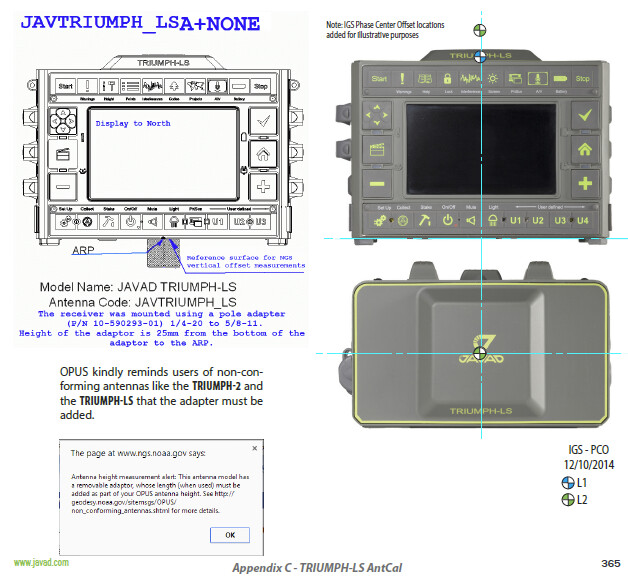
Emlid could help its users by providing them (and NGS, Geo ++, and other calibration services) with a proper diagram showing: not only the ARP (antenna reference point), and the NRP (north reference point), but also the physical locations of the PCOs like the drawings I prepared for the Javad Triumph Users Manual:
@EBE111057 - Good point. Sometimes, at least for me, the code isn’t enough and a drawing usually helps clear up questions for the specific antenna if/ when they arise, the LS ARP is one example (see above).
The other thing that drawings can help illustrate is why it’s important to orient the antenna; i.e., because of the often asymmetry of PCO locations.
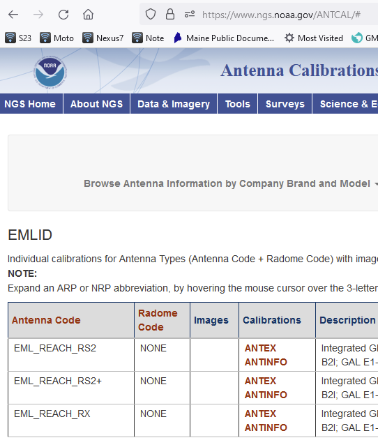
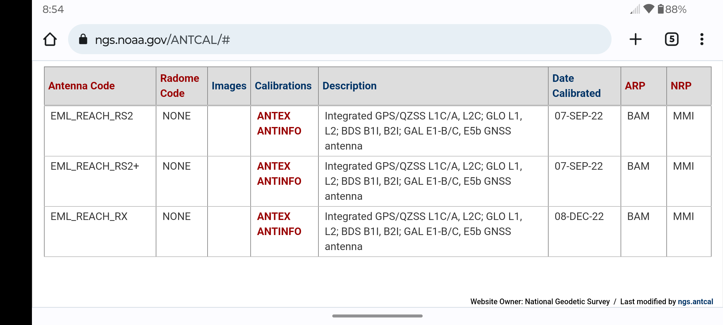
Such drawings indeed may help, but you can also find precise values for Reach RS2+ and Reach RX in the ANTINFO section.
Furthermore, the software interaction logic is optimized so that the user doesn’t have to think about it much. You only need to input the measured antenna height in Emlid Flow, the software adds the ARP offset automatically. You can read the post in our forum to find out more.
@kirill.pavlyuchuk - Thank you Kirill for the reply and the links. I’ve already referenced and graphed the ANTINFO - see:
As for the user not having to think much, that is a great mindset and goal for the developer and manufacturer. I know many surveyors are thankful for that just-get-er-done approach. I also know many surveyors (myself included) who would like to understand the things that happen in the black box and actually find enjoyment learning about stuff