Barry,
Please try Marc’s suggestions and inform us about the result.
Barry,
Please try Marc’s suggestions and inform us about the result.
OK will do 
log_23_2019-5-27-07-06-51.bin (1.1 MB)
That was after the reset as suggested by Tatiana
Which raspberry pi are you using mark
I just noticed something. I was changing the settings and the voltage reading momentarily jumped to .25 and then went back to zero?
Main (Flying) one is a 3 B+
Spare is a 2 B
Both have good servo rail voltage display (latest Mission planner over W10).
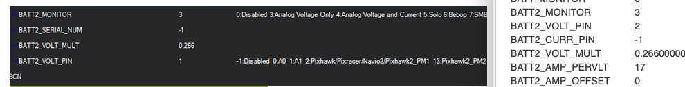
Battery 2 (servo rail) value display in QGroundControl is -1,…
Hello Marc. OK so I finally got voltage reading on Batt 1 but not on batt 2.hiwever when using multiplyer of 0.266 I get a reading of. 40 volt. When changing to 360 multiplyer I sort of get the correct reading but I varies anywhere from 14 to 17 volts
hello Marc and Tatiana
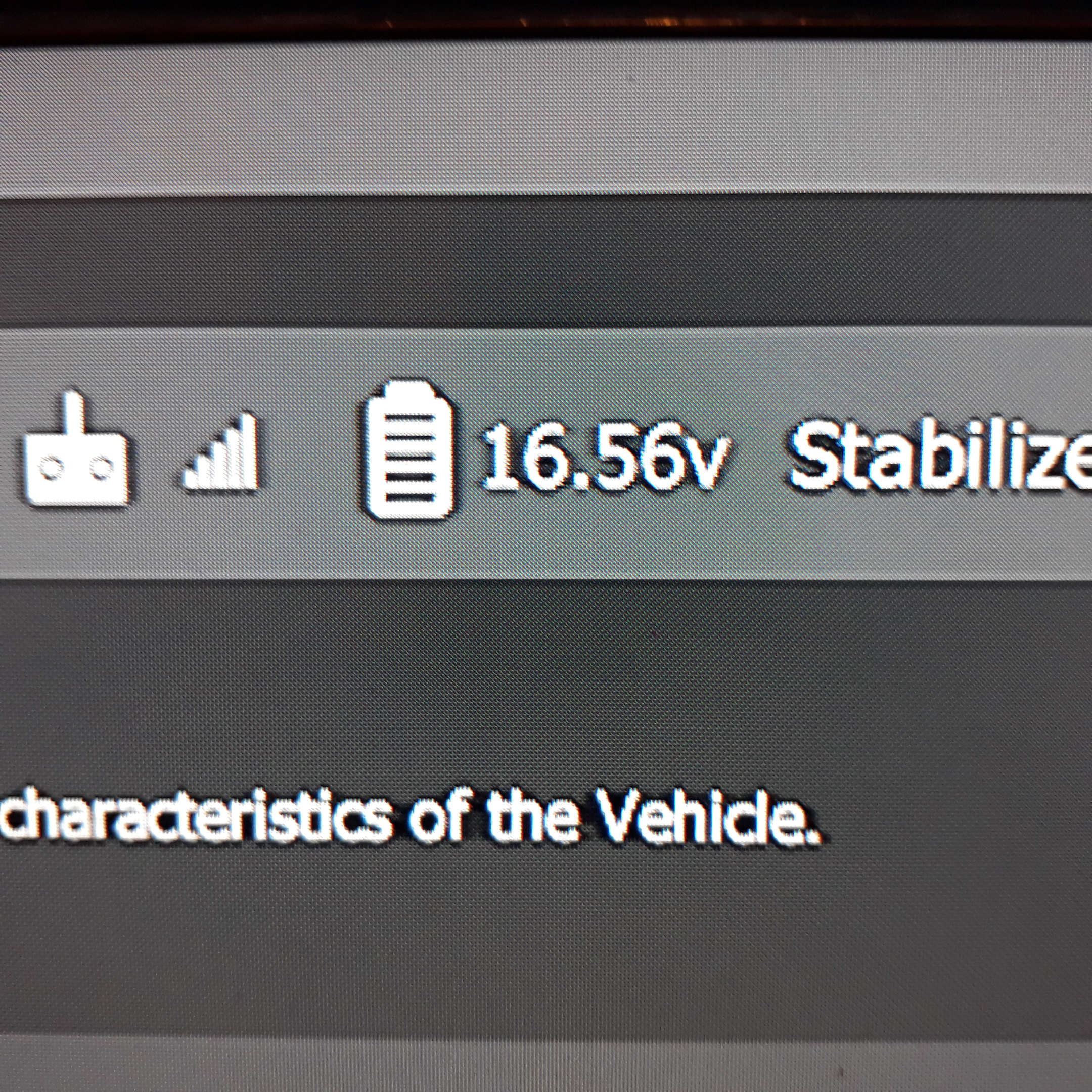
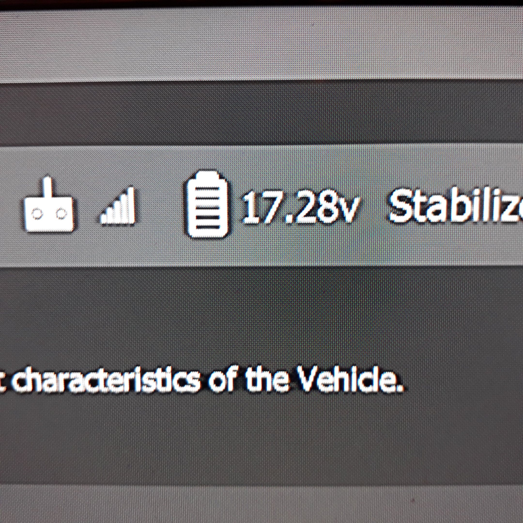
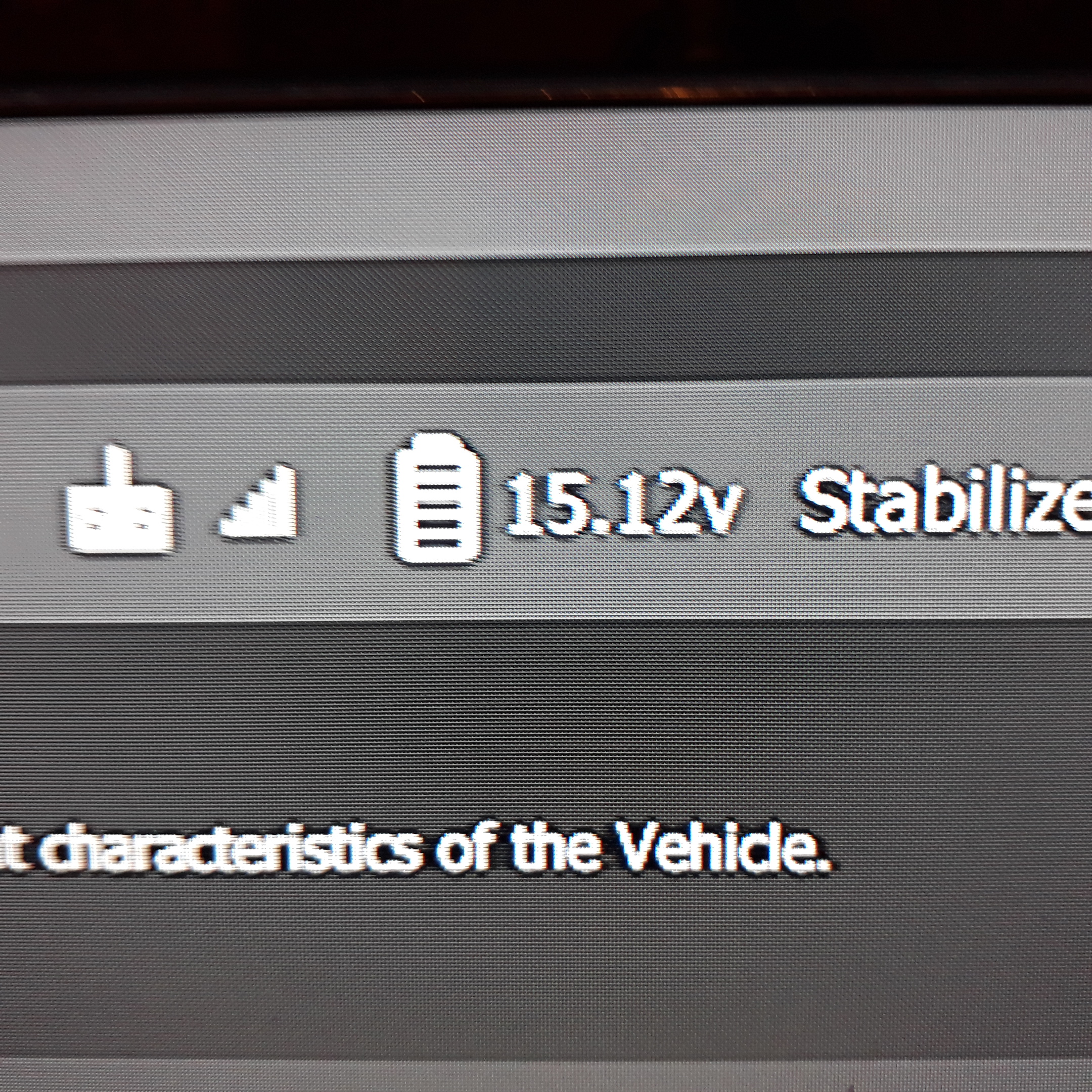
As you can see I am getting voltage readings on Batt 1 but not Batt 2, however as you can also see is that the voltage readings vary wildly and this happens in a couple of seconds
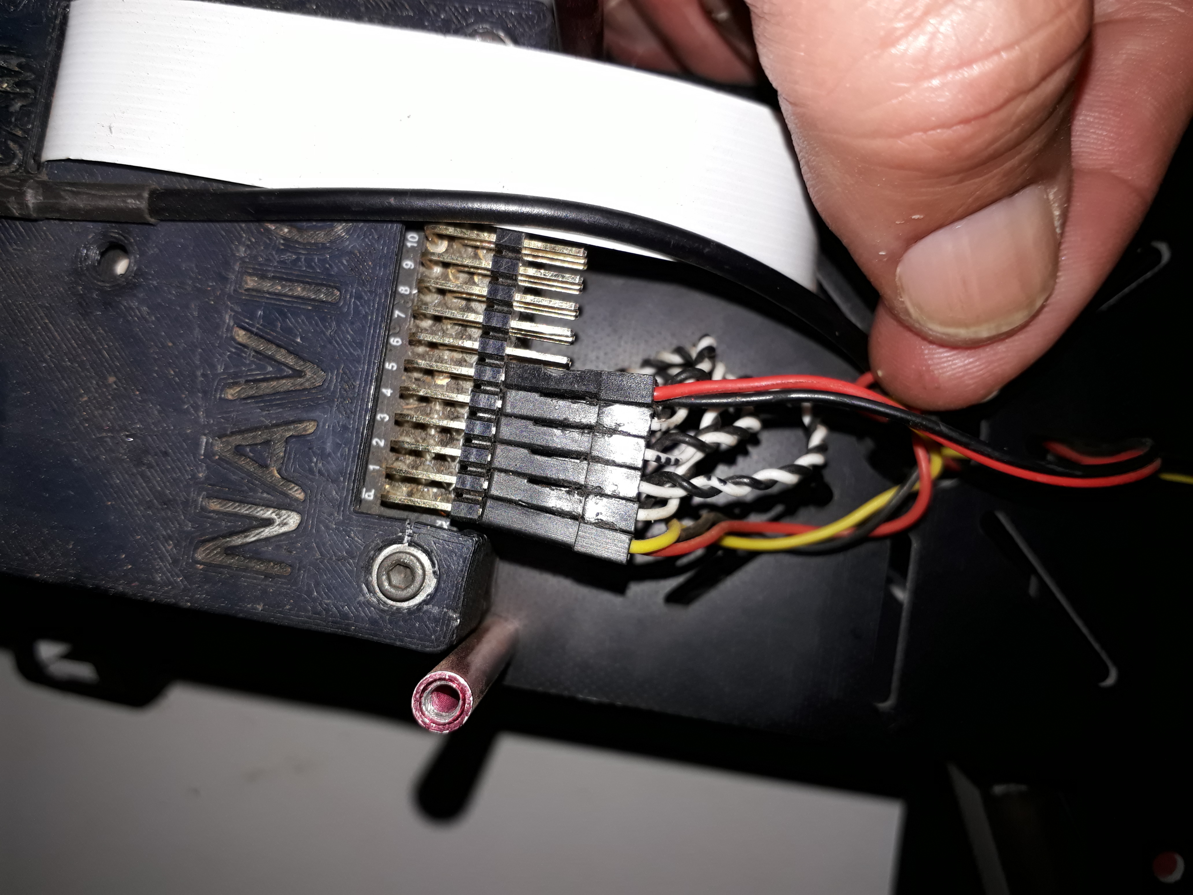
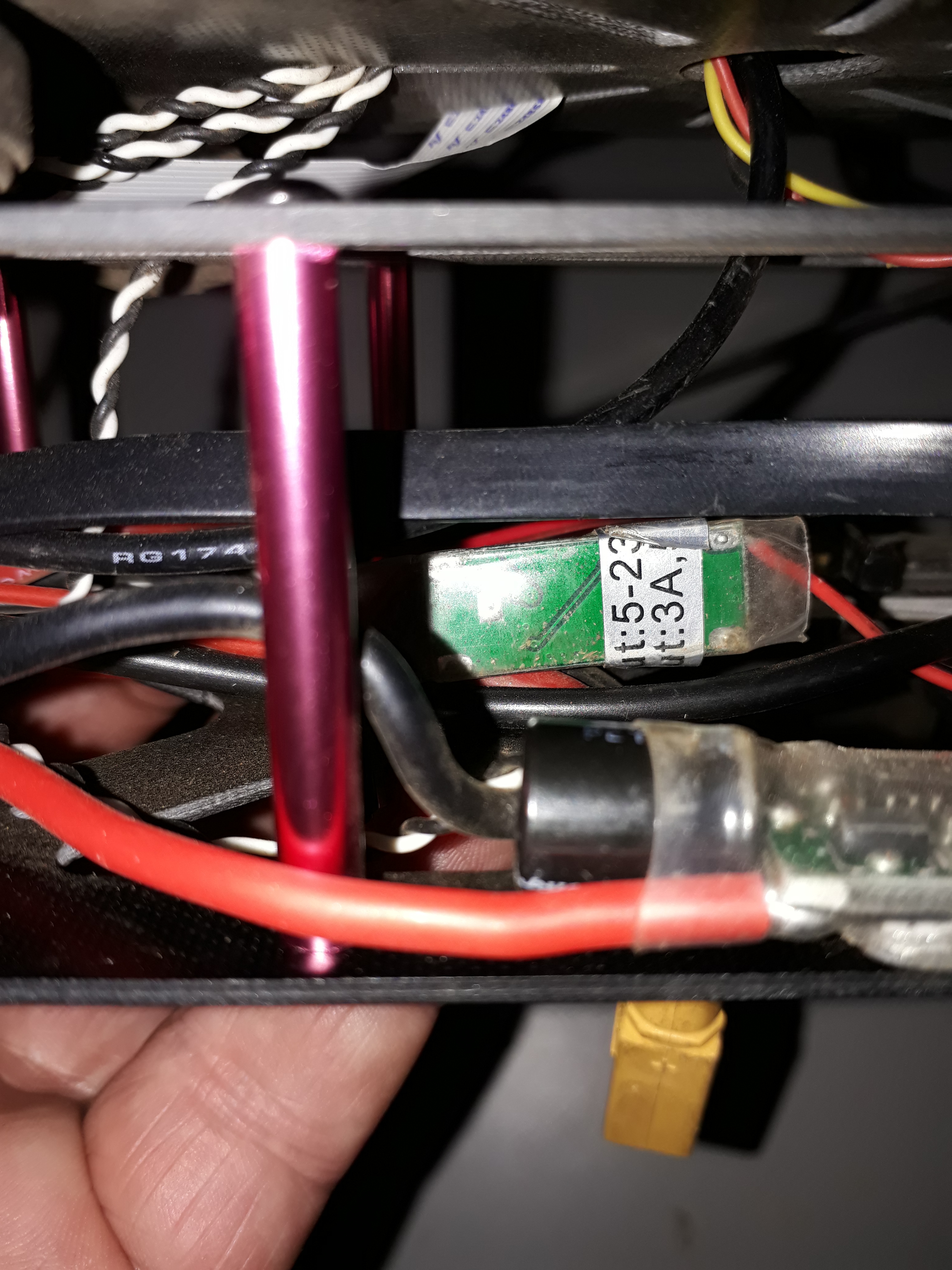
In these photos the Navio and Rpi 3 B+ is getting power from the ubec to via the servo rail. I get the same results when power is provided via the USB port. The measured voltage for this 4 s battery was 16v
Hi Barry,
Are you sure these screenshots show the voltage from the servo rail? I think you should tune the multiplier if it’s so. The voltage on the servo rail barely exceeds 5V.
No those were from the USB port. The voltage reading behaves the same from the voltage rail where the readings would jump any where from 2 to 4 volts
May I ask you to clarify what do you use to power Navio2? I’m not sure I understand the setup scheme correctly. It’d be great if you post some hardware setup photos as well.
It is a 5 volt Ubec that is powering the servo rail.
Hi @Barry_Bolton,
Let’s try to sum up all the information we have for now on this topic as I’m getting confused and not sure I fully understand what are the difficulties you have at this stage.
Could you please clarify have you managed to display servo rails readings in QGC or MP?
What about USB port voltage readings? Can I ask you to elaborate on your hardware setup scheme? Some photos would be of much help.
Please use the following template when you describe the issue. This will help us a lot.
- Detailed problem description. How does observed behavior differ from the expected one?
- Your step by step actions.
- Picture of the setup and connection scheme.
- If using any additional hardware please provide exact make and model.
Please try to be as descriptive as it’s possible.
I use a 5 volt 3 amp UBEC to power the Navio2+ raspberry pi 3B+ when I am flying. The UBEC powers the whole set up via the servo rail
When bench testing I use a Raspberry pi power supply that I connect to the USB port of the Raspberry PI.
The output that is in the display of both Qgroundcontrol and Mission planner jumps around by as much as 2 volts every couple of seconds regardless of what is powering the Navio + raspberrypi. I used 4 s batteries and the voltage over a couple of seconds will vary from 14.6 volts to as much as 17 volts sometimes.
I will make a video about this and post it as well
Hi Barry,
May I ask you to advise whether you use the following power supply scheme?
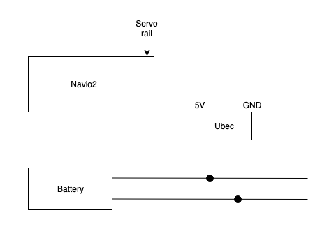
yes
Hi @Barry_Bolton,
As far as I understand, you’re trying to observe the voltage from the battery connected over Ubec to Servo rail. However, it’s not possible as servo rail always tries to maintain the voltage in 5V.
According to the servo rail measurements you posted earlier, I can suggest that: