So clearly the bridge is happening, your already moved onto decoding all settings. Still busy doing earthwork before winter, but you really have all the elements needed. RS2 will learn to talk to strangers.
It does “remeber” its settings. Instead of connecting to my monitor I connected to my laptop and looked at it with SNIP.
I viewed all the messages that I was sending from my RS2 via LoRa. The only issue I have now is they are not coming in at the proper rate. Their should be a steady flow of messages with the following settings
1006 - 0.1Hz
1074 - 2 Hz
1084 - 2 Hz
1230 - 1Hz
1008 - 0.1 Hz
1033 - 0.1 Hz
I used my Nano to put the GPIO_0/1/2 to low. At one point I disconnected one of them (GPIO_2) from the Nano and she started to sing but, it only lasted for a bit. This may have put the LoRa in “wake mode” but I am not sure. I haven’t taken my M2 LoRa module apart as I do not want to break it. I am not sure which GPIO cable is attached to which P1 or P2 on the LM-210H.
I am going to write another sketch pulling GPIO_0/1 low and GPIO_2 high and see what I get.
Out of play time for today. 
I had more “tinker time” today.
I monitored the M2 on powerup. It does send the config so I think I want to add the config to my Nano script.
I think this will have me.
As for my rate not being fast enough, I found I had a bad breadboard jumper wire. The end pin had pulled out partially.
The three GPIO wires are for two things. One of them communicates the Module’s operation status (BZ), this is connected to GPIO_0. The BZ cable from the radio to GPIO_0 is normally HIGH.
GPIO_1 & 2 are connected to P1 & P2 of the LM-210H radio. These are used to set the mode of the radio by setting them HIGH or LOW.
Mode 1: Normal mode (P1=0, P2=0)
Mode 2: Wake-up mode (P1=0, P2=1)
Mode 3: Power-saving mode (P1=1, P2=0)
Mode 4: Setup mode (P1=1, P2=1)
When running connected to the M2 it is in Mode 1. When you change a setting on the radio (Freq or Kb/s) it temporarily goes to Mode 4 to set the config then back to Mode 1. When this happens the BZ cable goes LOW.
All data appears to be transmitted on the RX/TX lines. Even though the radio is set for 38,400 baud, all configuration is done at 9600 baud using Hex.
Yes.
I know, it is hard to draw with MS Paint.
I am not using different manufactures, I am using the M2 radio module sold by Emlid. I just need to have the configuration settings applied with it not connected to the M2
Hi @jp-drain-sol,
We’re always ready to share information and help solve issues as much as we can. However, we can’t share the internal LoRa configuration settings since this isn’t open source information.
Alright, thanks. I will continue to try to sniff it out.
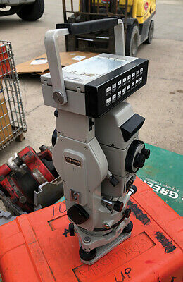
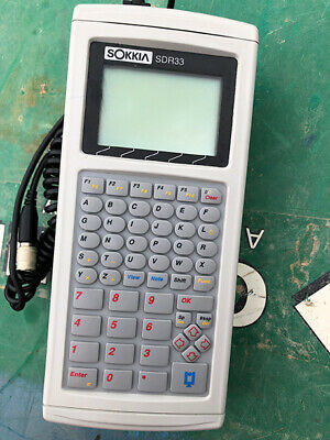
Great job jp-drain-sol ! This reminds me of the time trying to interface an HP48SX to a Leitz Sokkia SDM3 manual total station. It was at the time a great instrument in the late 70’s early 80’s. I had programmed the calc with simple traverse routines for reduction from a field book and usually reduced the mornings traverse during lunch at the truck. The calc had a simple rs232 interface that was used to interface with the instrument. The instrument had a keyboard for EDM distance measurement on top along with a digital readout screen right above the eyepiece. The angles were measured and recorded by viewing the micrometer next to the eyepiece. No fancy digital display encoder for this. I had found out from an instrument calibrations technician that there was an rs232 port hidden in the keyboard-computer area for a future data recorder that Leitz Sokkia had developed and was planning on releasing for an upgraded model.
There was no documentation on the instrument side for this. After borrowing a cheap ocilliscope for about a month (I had to learn how to use it), I finally had the calc receiving data from the EDM. Most of the work was hit and miss by viewing the voltage increase when the measure button was pressed. After about two months, I had the EDM communicating with the calc and downloading the slope and computed horizontal distances. I thought I was a genius by developing the cord and calc software ! I was in my early twenties and thought I could sell this to Leitz Sokkia and become a millionaire !! Low and behold right after I had a working package, they had came out with their upgraded model with a data collector/controller. I was disappointed but very proud of myself figuring all this out. My dreams of selling this to Leitz Sokkia ended pretty quickly when I saw the newer model in the showroom.
I miss those feelings of accomplishments. I guess that’s why I enjoy simple programming although I haven’t done any in awhile due to running a business and having all the worries that go along with it.
Keep up the good work jp-drain-sol !! You’ll figure it out. I look forward reading about your work. It will benefit a lot of people.


I would love a cheap 0.5 or 1watt external UHF modem for M2. Is it possible?
Most survey grade receivers come with 1watt internal UHF modem 430-470Mhz with various supported protocols.
I have used a set of QWinOut 3DR Radios. There are all different brands out there. QWinOut has both a USB and a 4 wire connector on both radios. Most brands have a wire connector on one and a USB A plug on the other. That might be fine in your application.
I knew I would be wiring both, one to my M2 and one to my radio box that I made in the picture above in post 15.
I would really like the internal radio of the RS2 to be able to communicate with preferable an Emlid product that receives their LoRa signal. This way I could add a radio to an existing Trimble system and have a reasonably priced base station.
Trimble’s Ag base station is over $14000 now and you cannot get them. I have had 3 on order since April of this year and my Trimble Rep cannot tell me when they will be in. “Projected delivery date” (which hasn’t meant anything since COVID) is now mid December. This is the 4th corrected estimated or projected date they have given me on this.
I have another solution using an RFD900+ at the base and a Qwinout 3DR at my Trimble rover running multipoint software in the radios. This solution works fine but, like I say, why add a radio when there is an internal radio that could be used.
BTW, with guys our age we are going to start telling people about how we were going to invent the wheel… till that guy from the B. C. Comic strip beat us to it. LOL
Persistence paid off! I am too stubborn to give up.
I got it working this evening without the M2 connected.
Tomorrow night I will make another radio box and mount my equipment in it. If I still have time, I will test it with my Trimble monitor.
Way to go JP!
This will really make the RS2 more useful than it already is. “EMLID Lora Bridge” is born!
RS2 on the side of the field and the bridge in the cab, European farmers especially will love this.
Thank you for the encouragement and help.
No time to tinker today. I am making some homebrew beer. YUM!
I started mapping the Hex values for the different radio frequencies. Took about an hour to do 902-904 stepping 0.1 each time.
I know now how to speed it up so this evening, I should be able to complete 904.1 through 915.
Working on my Nano sketch to view/change the radio frequencies. Makes me wish I would have stayed current on my computer programming that I took back in high school. Back then (1980) it was Applesoft BASIC on a Apple II computer or, if you were lucky, they had one Apple II+ which had a color monitor.
I have had to do a bunch or research on adding a 4 X 4 keypad, LCD Module with I2C Interface, serial.read/write/print, HEX, digital.read/write, using an array to name a few.
I REALLY WANT TO THANK THIS COMMUNITY! While doing all this research on Arduino’s forum there are so many naysayers or negative comments on about every subject I have researched. Most people state upfront they are a noobie yet they have to tear them down in their responses/comments. I have not experienced that here. THANKS
LOL Arduino forum.
Had similar experience, a whole lot of people who really are not that helpful, say everything you are doing is wrong, but offer no way to do it correctly if there was a way.
There was two very aged programmers on Arduino forum who actually helped me when I started programming C. The rest I think are just University students trying to sabotage each others projects.
I wasn’t following the whole thread, but noticed your last comments and understood that I can’t pass by 
I think it’s worth mentioning that you are the part of our community who make this forum a healthy and open place where everyone is free to share skills, knowledge and ask a question.
One of the most personal and meaningful insights I gained when I joined Emlid a few years ago is that no one question is silly. And that always inspires me to see how many people here share the same values 
Apologies firstly for being somewhat AWOL and missing this thread entirely.
Really well done. You have succeeded in an amazing testament of your skills, patience and tenacity.
Many folks and many farmers especially will be very appreciative you have helped open up another dimension of capability of the product.
What an amazing achievement!
Great achievement JP !!
I started out with FORTRAN in college. Usually spent afternoons in the “computer lab” programming and checking and rechecking instructions in my code and usually submitted in evening for processing.
We usually met first thing in the morning next day to see if our programs worked. It was usually the dreaded “1015” error (read unexpected character). If it was a long line of code you literally had to inspect each line for the wrong input value or character. The professor explained to us “that’s one reason why you keep your code as short as possible”.
No display output from the computer, just a print out of your code and successful program results IF YOU WERE LUCKY and the great result code 2005 “end of file, end of record”. If you were successful on your first run, you had to buy the whole class (usually 5-6) a round of beer that night.
Great times… keep up the good work JP !!
FORTRAN is still used today as it is a great compiler and is not that that hard to learn, it’s a great doorway to C+ or C++.
Now that we are in our wet/cold season, I will have time to build the Nano sketch. Being rusty/new, I am building it one section at a time. Try it, if it works build another section, try it alone, if it works add it to the 1st and so on.
I am incorporating a 4 X 4 keypad to change frequency/baud/kbps and an LCD to display current settings and what you are changing. For a noobie, quite a challenge.


