@bide on Reach RS2

@bide on Reach RS2:

Emlid has been kind enough to provide pre-production Reach RS2 units to a few individuals. My thanks to Emlid for the opportunity to be one of the first to work with RS2 and be able to share impressions and observations about it with the community.

In case you missed it, here is some work already posted by @TB_RTK:
RS2 - The 33/66km RTK session with ntrip/simcard

Let us get right into the important stuff and answer your burning questions about RS2.

1st stop is the kitchen:

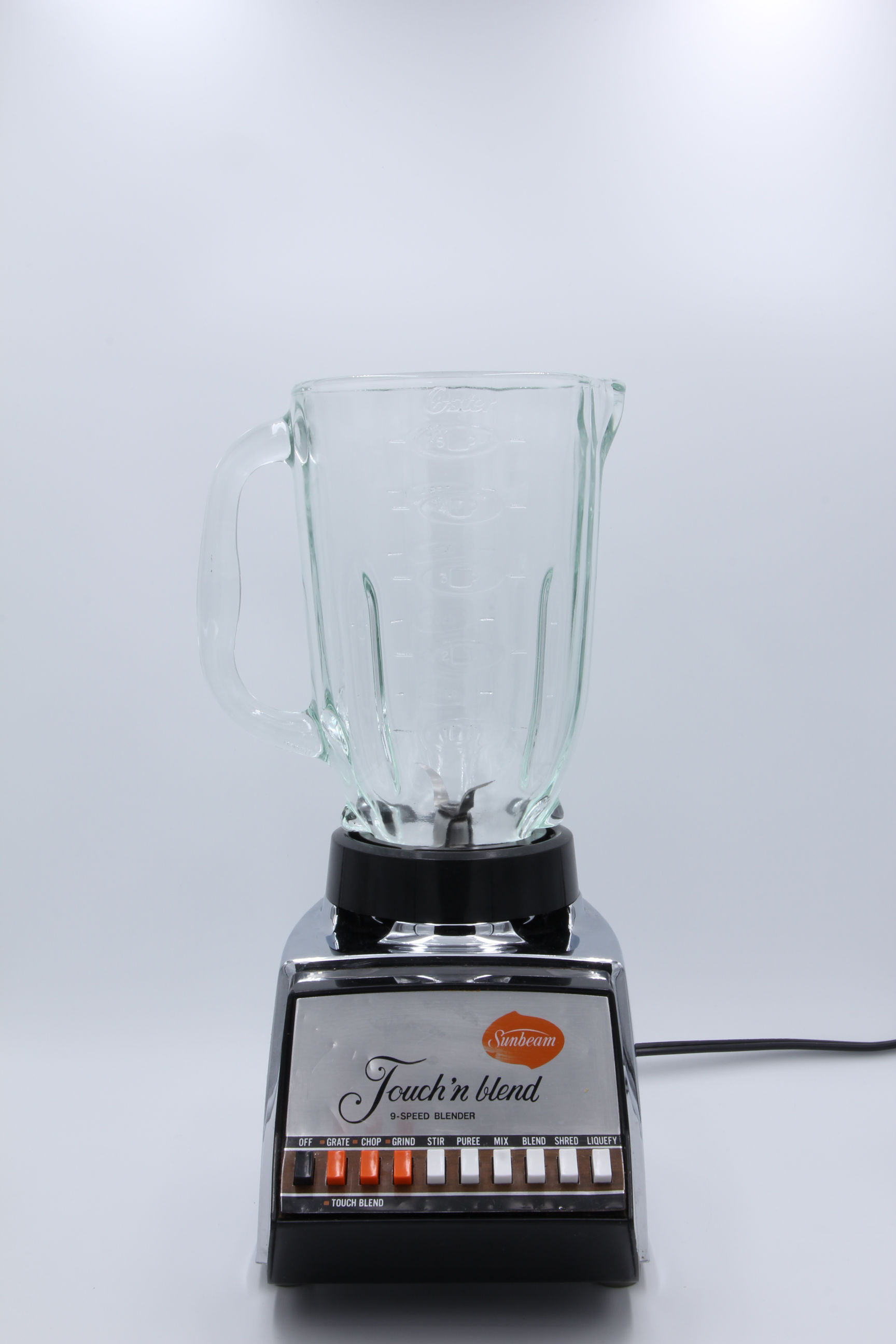
i. Reach RS2: Does it blend?

Click to find out

I don’t think so, but well … you know … maybe it does :thinking:

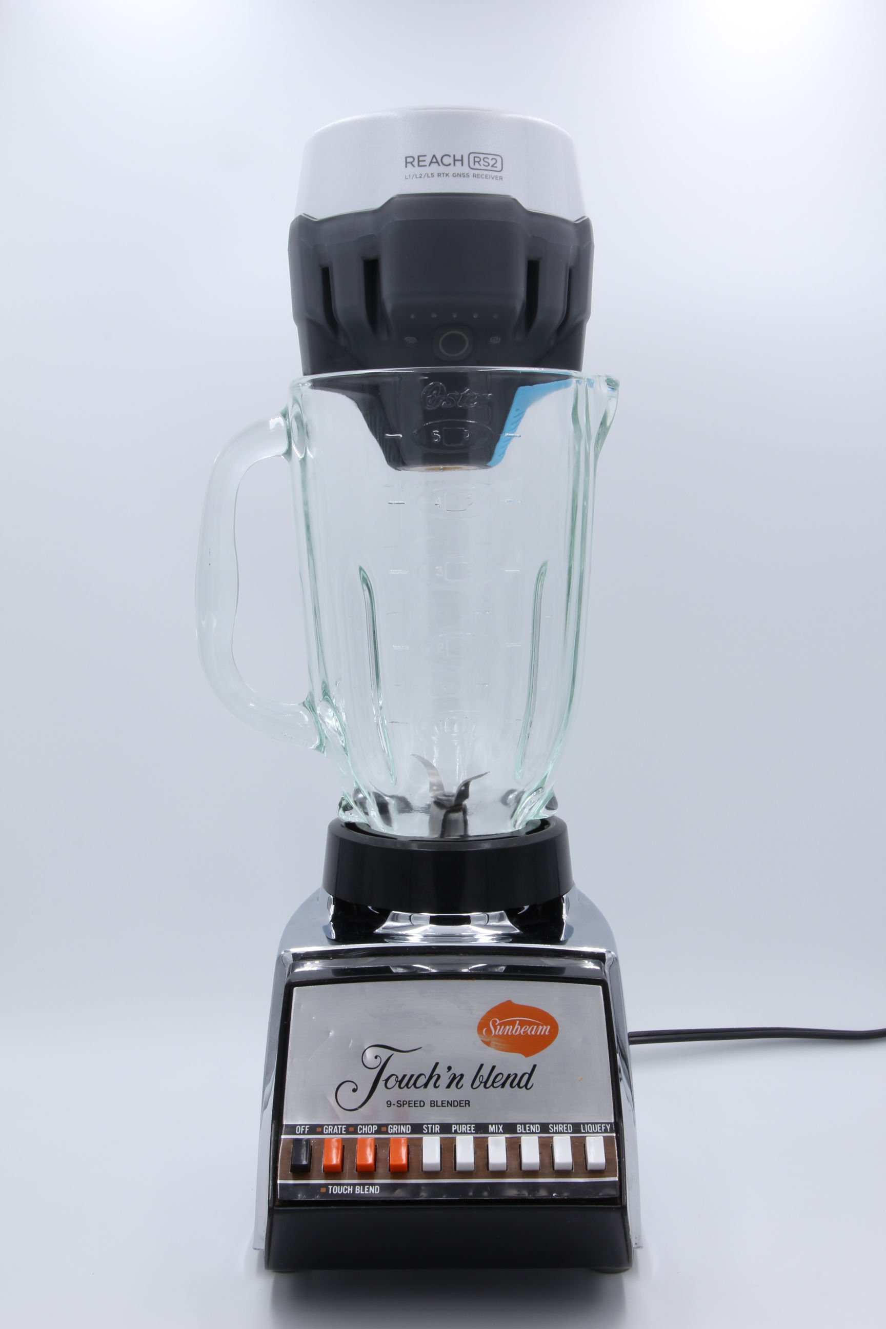
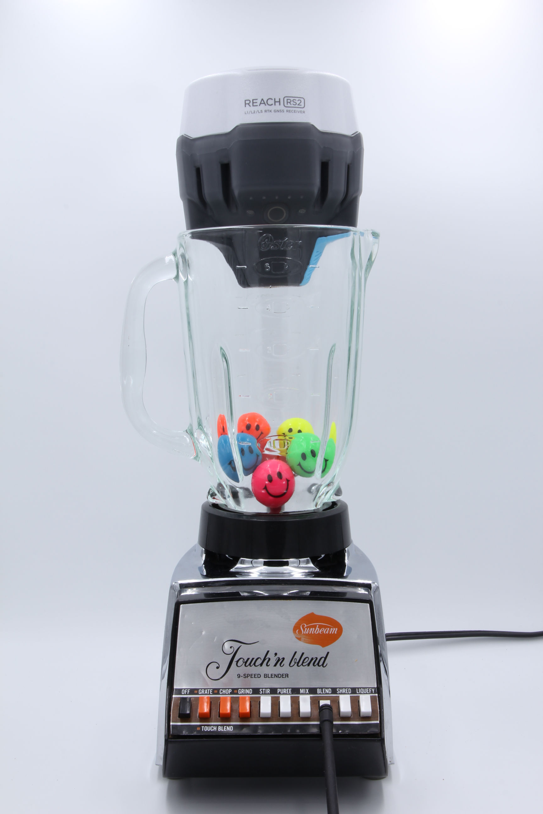
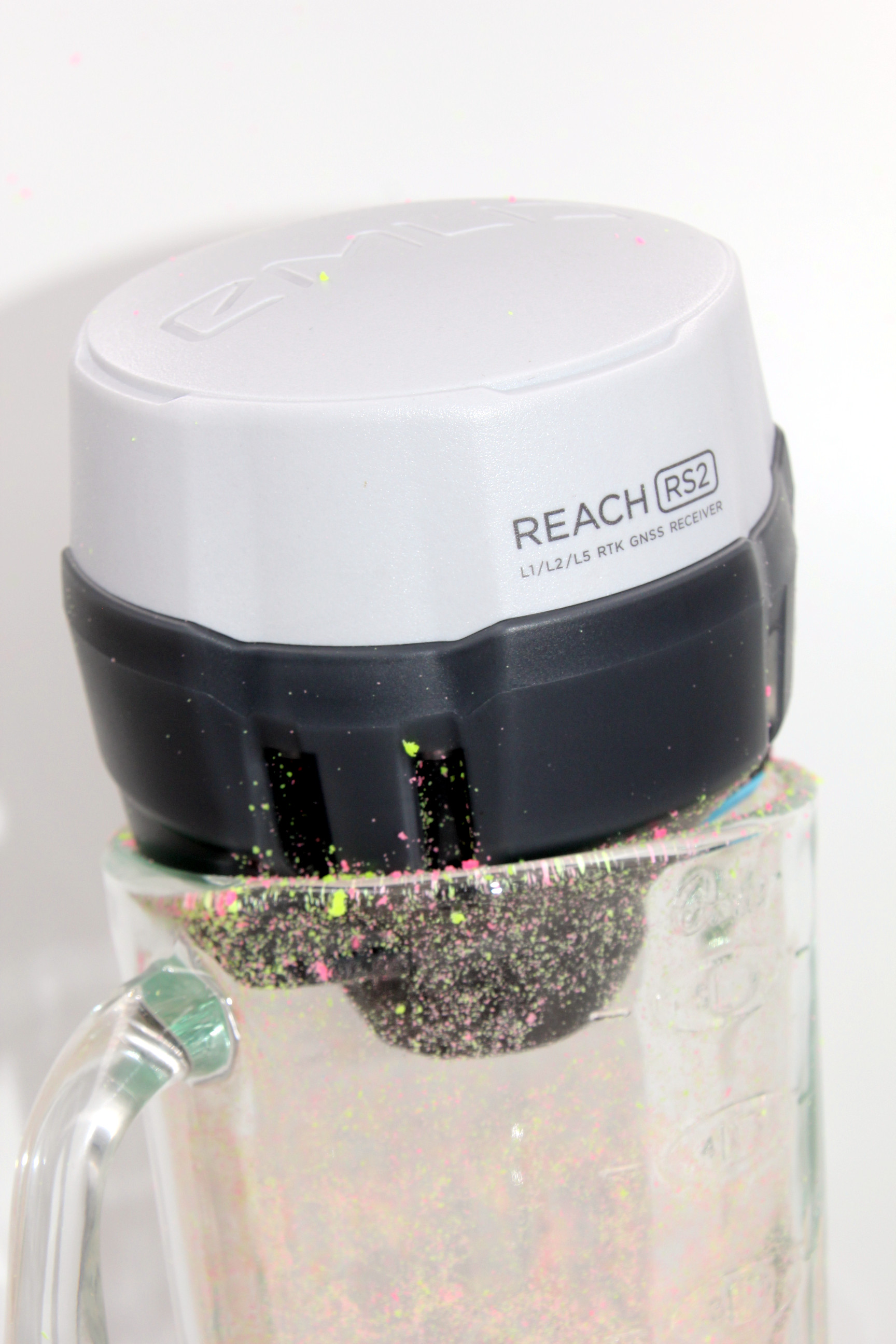
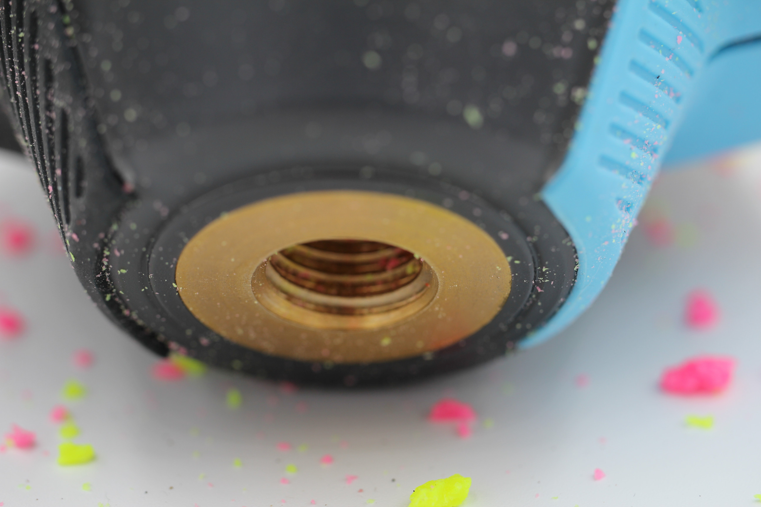
Reach RS2 almost blended, but luckily due to its phyiscal dimensions it did not. However, it does seem to be able to act in place of the stopper (the lid) of the blender. With this in mind, I would recommend one for every kitchen. :stuck_out_tongue_closed_eyes:

Please don’t ask me to explain how this has anything to do with GNSS receiver performance. :grimacing:

ii. Reach RS2: Does it roast?

Click to find out

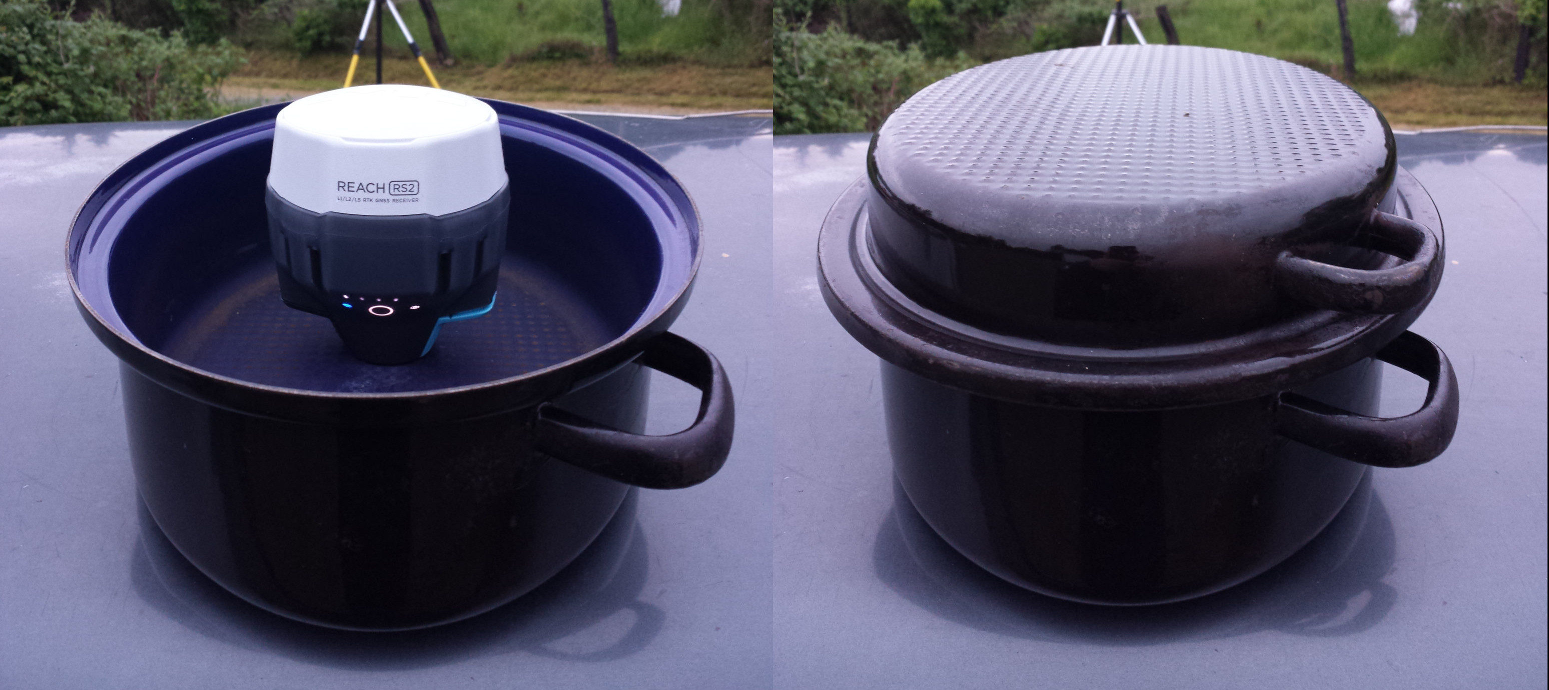
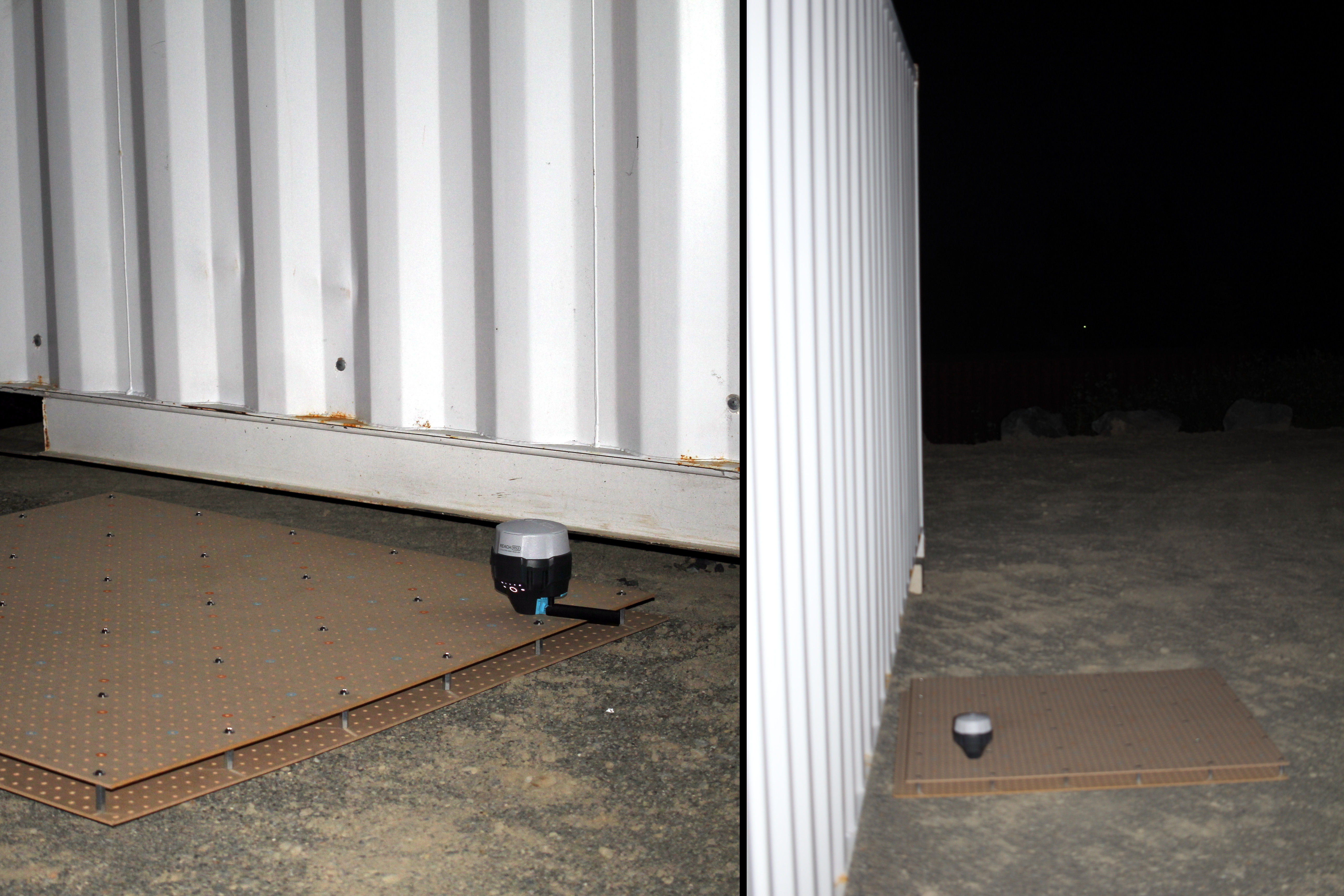
This not about heat or roasting in an oven, but it does have something to do with a roasting pan.

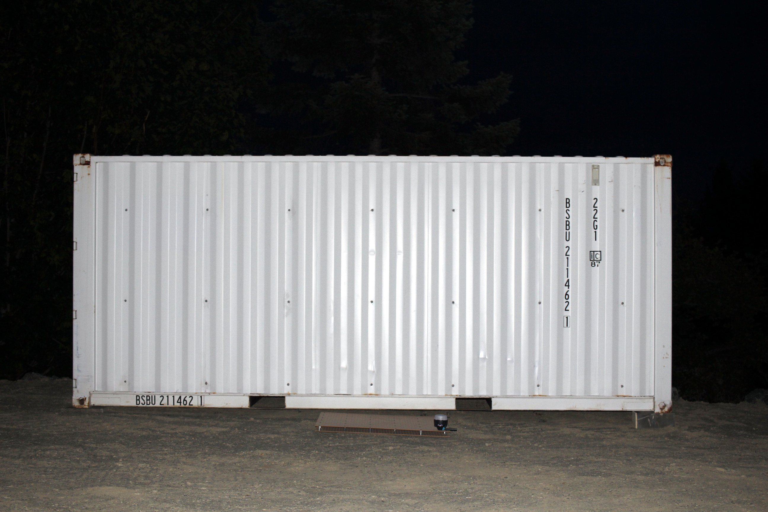
RS2 was enclosed inside the steel container in order to block satellite reception and break the position solution. This is a quick and efficient way of testing the time it takes for RS2 to recover from a complete satellite blockage.

After tens of repeated tests, it was observed that most of the time RS2 would regain the fix in 10-20 seconds. To be fair, there were times it would take much longer than that, but there were also other contributing factors to consider. For example, because of the signal blockage, the rover would sometimes loose the base corrections as well, and then have to reestablish those first before it could work on the position solution. These test conditions were pretty extreme and RS2 behaved very well in spite of them. Note, the specified convergence time is ‘typically 5 seconds’, which is about right if your RS2 isn’t being housed inside a metal pan and covered intermittently while passersby cast confused looks at you.

iii. Reach RS2: Can you see it in the dark?

Click to find out

OK, we’re out of the kitchen now, and standing outside in the dark. And thanks to the LED display panel, yes you can see Reach RS2 in the dark!

Here is a night-time photo showing full battery (top) and almost dead battery (bottom):

  • apologies for the camera blur

iv. Reach RS2: Does it want to play a game?

Click to find out

Rather than make up a test jig with fixed distances or break out the laser or tape measure every time, there must be an easier way to make repeatable measurements:

Enter the board game with equally spaced holes in a grid formation.
peg_board_game_1

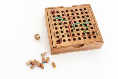
It looks like a perfect test bed to me!


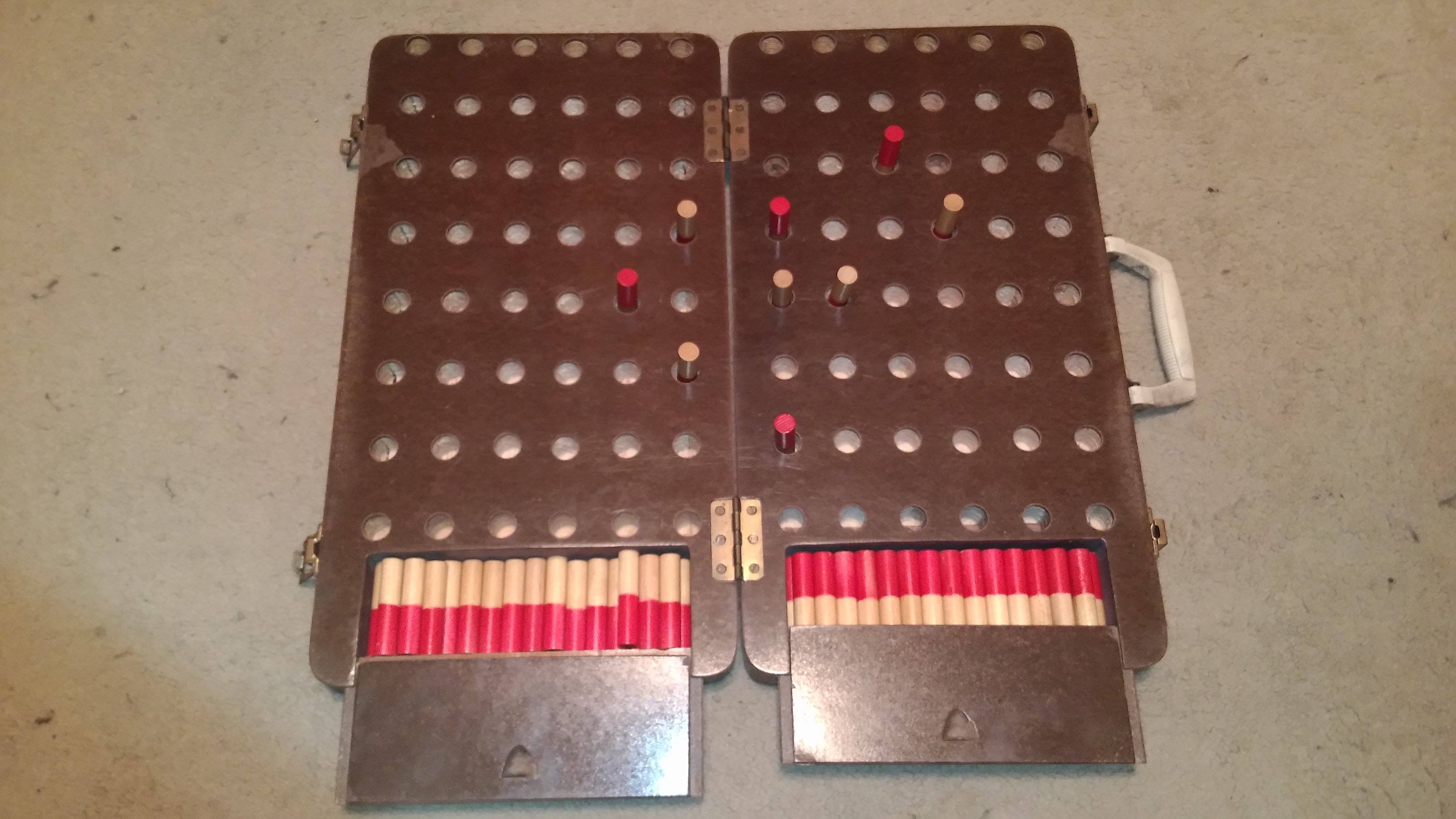
This one above is actually a dexterity test rig:
What is this game with a 12x8 pegboard and 59 double sided pegs? - Board & Card Games Stack Exchange

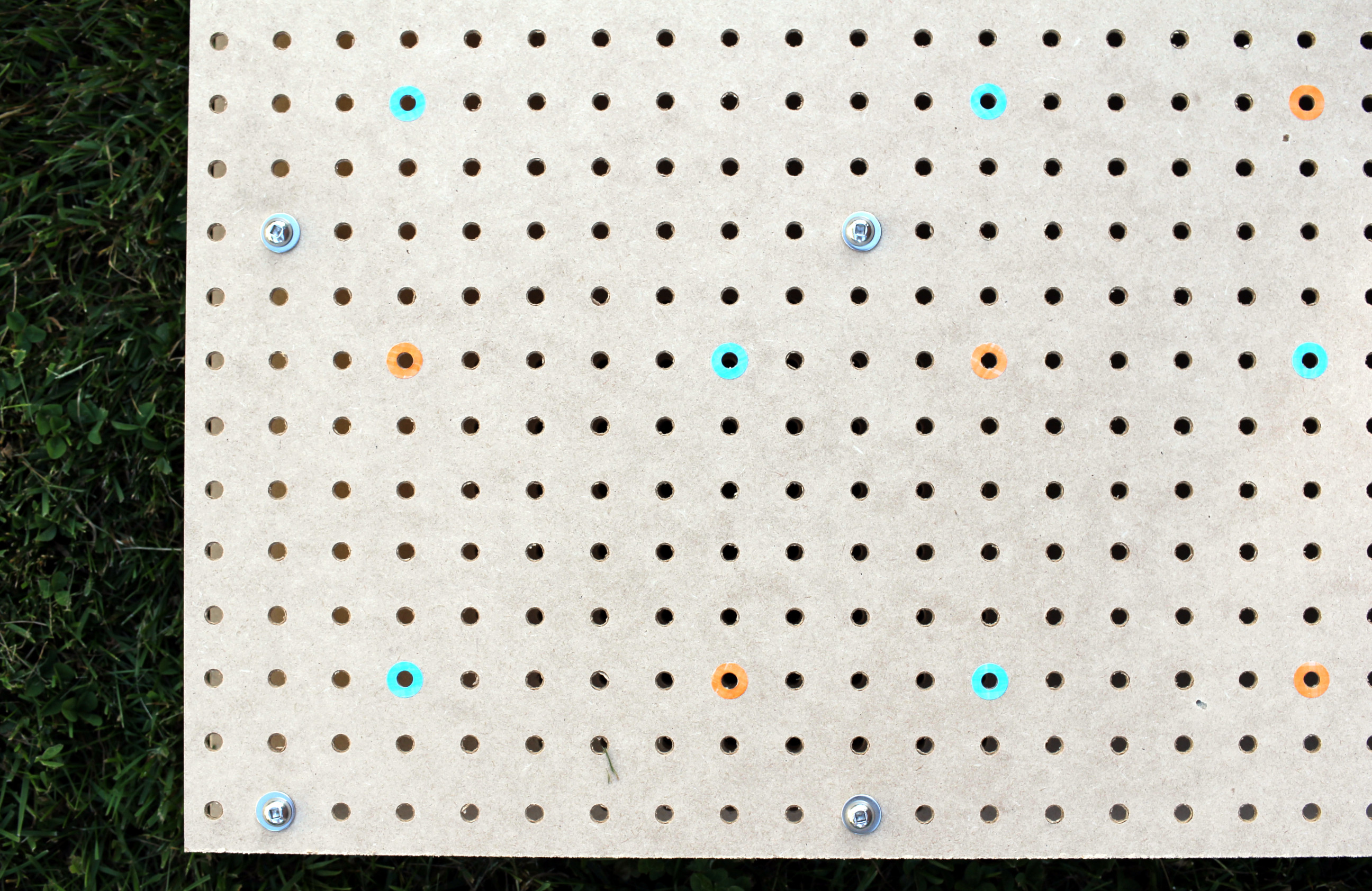
But where to find such a thing? I think the best place to find this kind of material is in the garage:

garage_pegboard

Yep, that looks good, but let’s not disturb the tools. We’ll find some unused pegboard material:

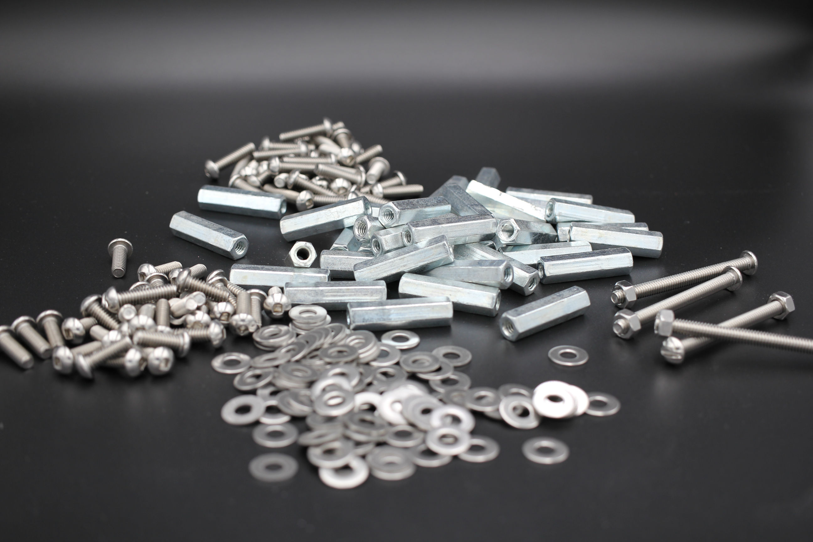
Some fasteners are also needed:

Fast forward to the finished grid.

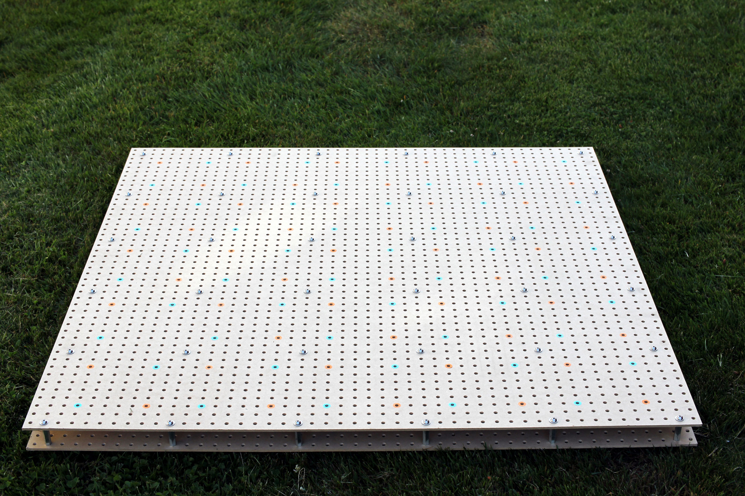
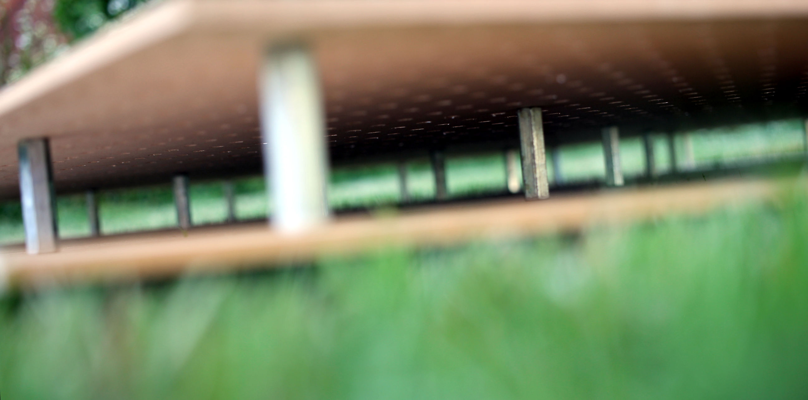
The number of metal standoffs make this a very rigid unit now.

A close-up of the grid.

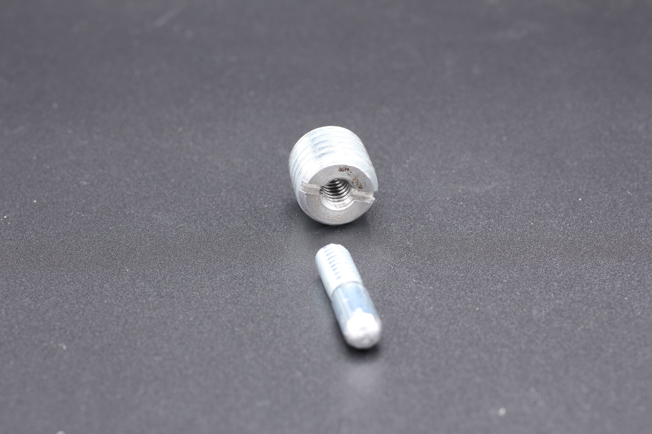
Here is a thread adapter (5/8" to 1/4") and a threaded peg that was made from a regular bolt.

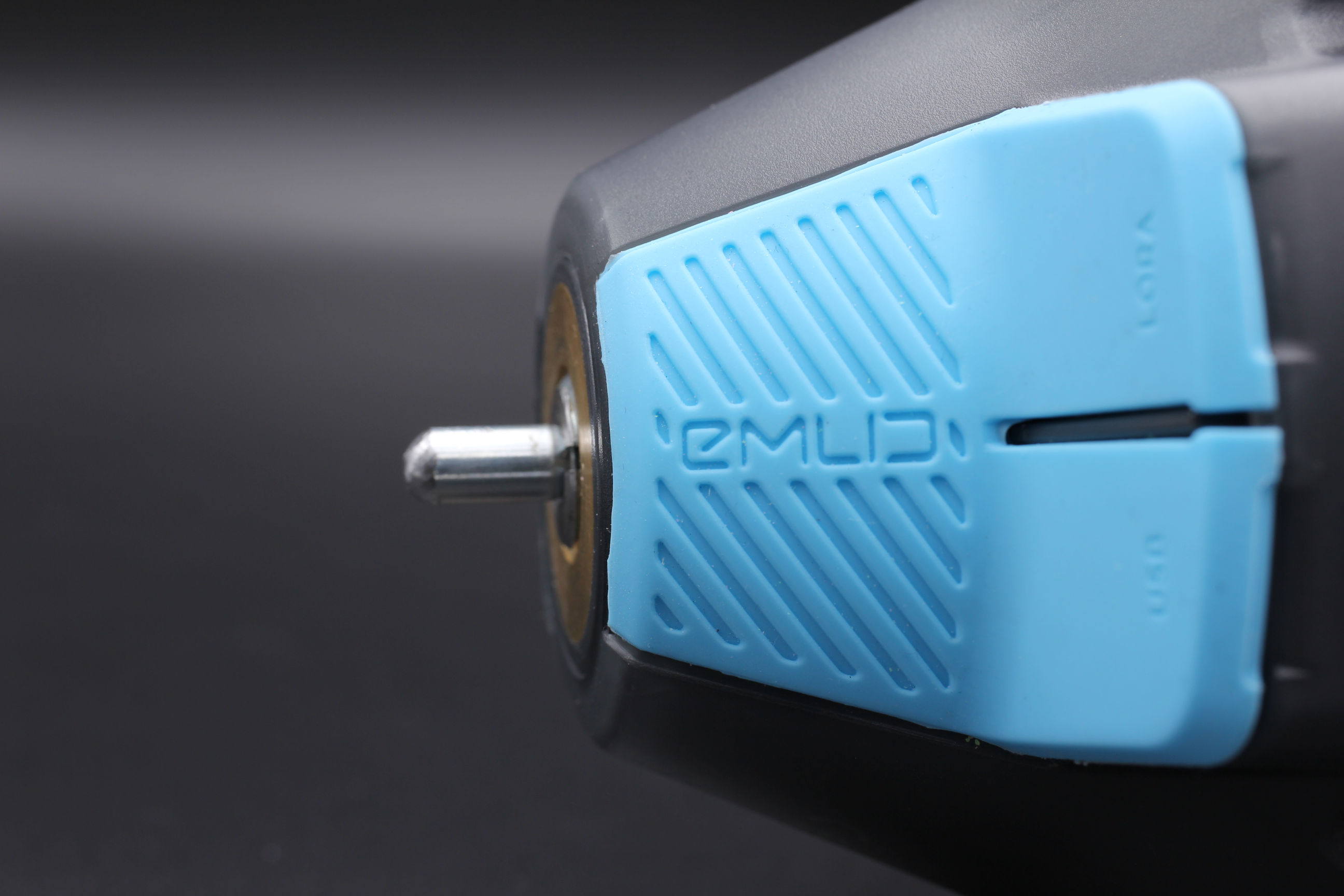
Peg mount installed in RS2.

This is RS2 pegged into a position on the grid.

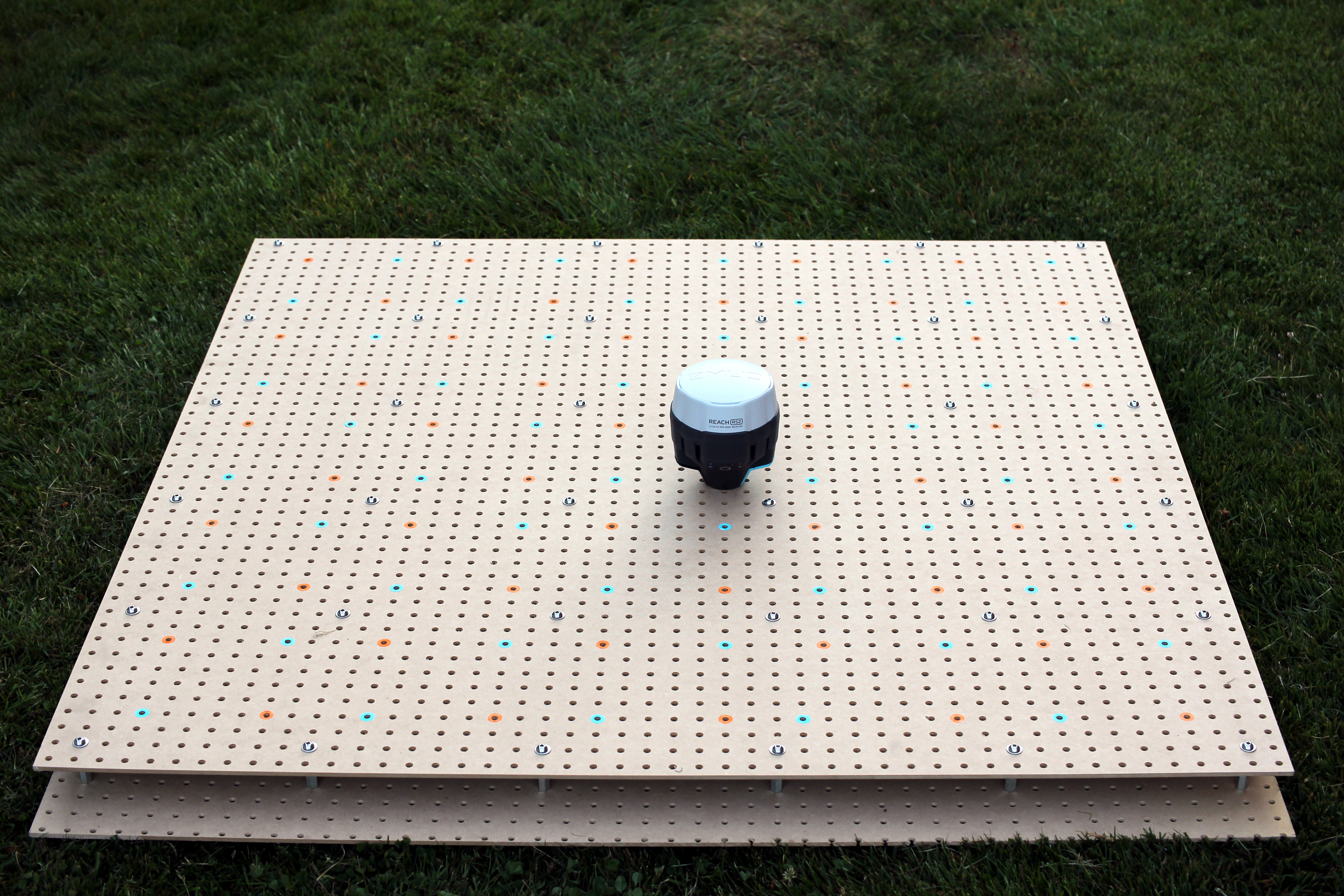
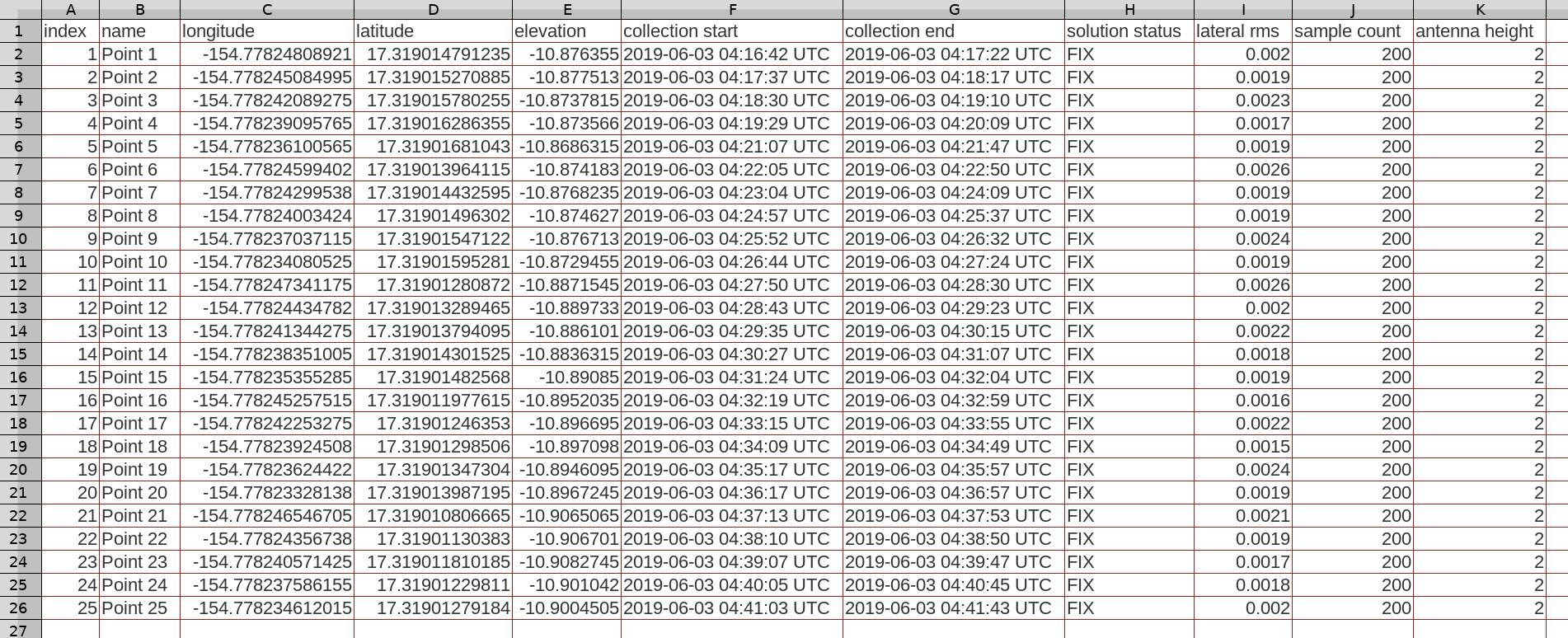
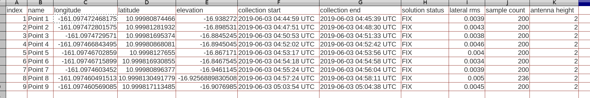
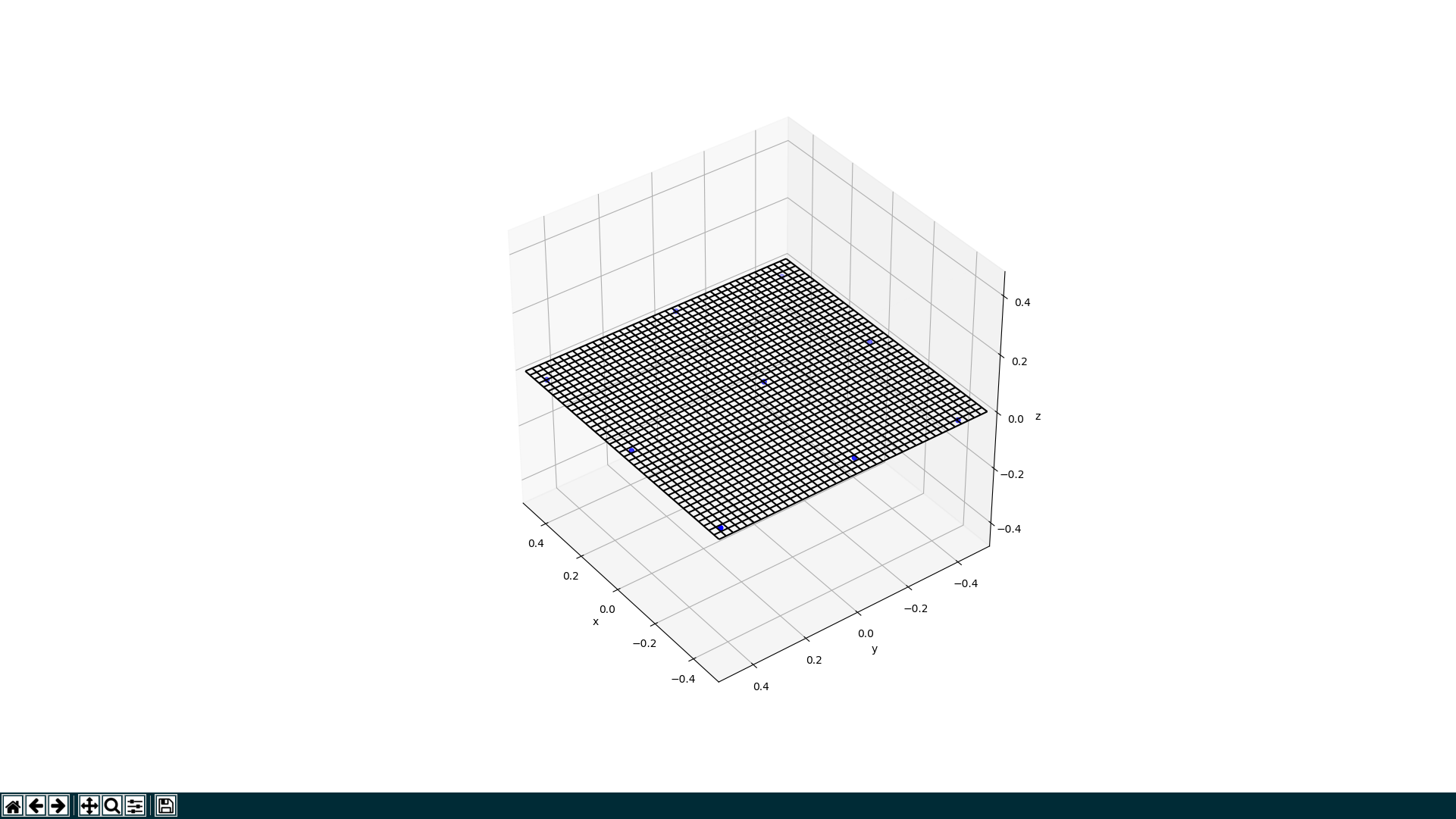
This is the result of a 25 point short-baseline survey project. The rover was pegged into a 5 x 5 grid pattern. A survey project was created and ‘fix’ points were collected with the default settings of: 40 seconds, 0.005 precision, and a DOP of 2.

This is the exported survey project file. The average of the ‘lateral rms’ column is under 2mm:
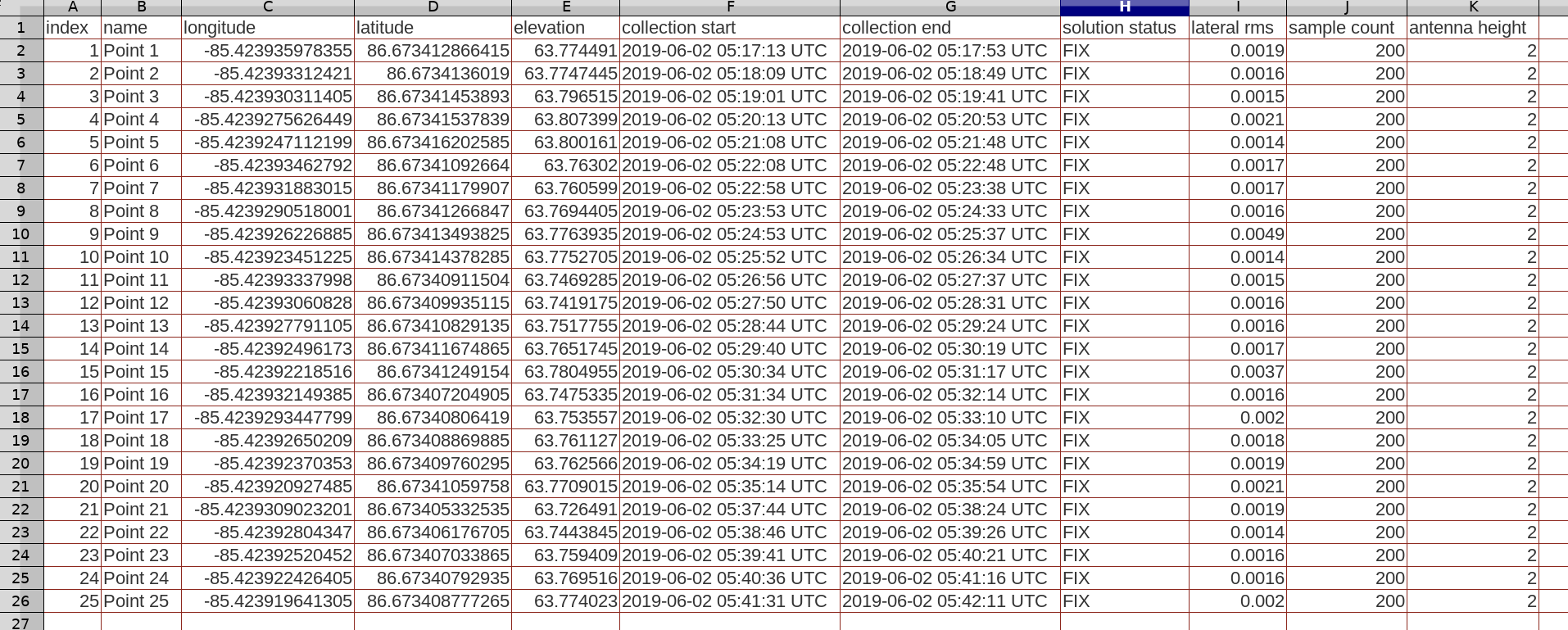

(llh anonymized)

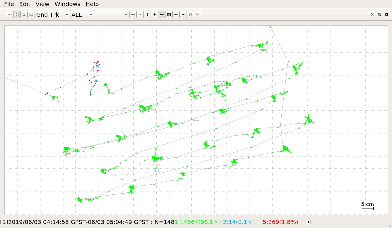
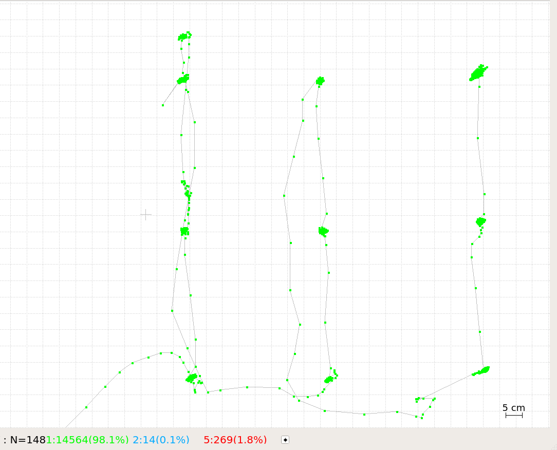
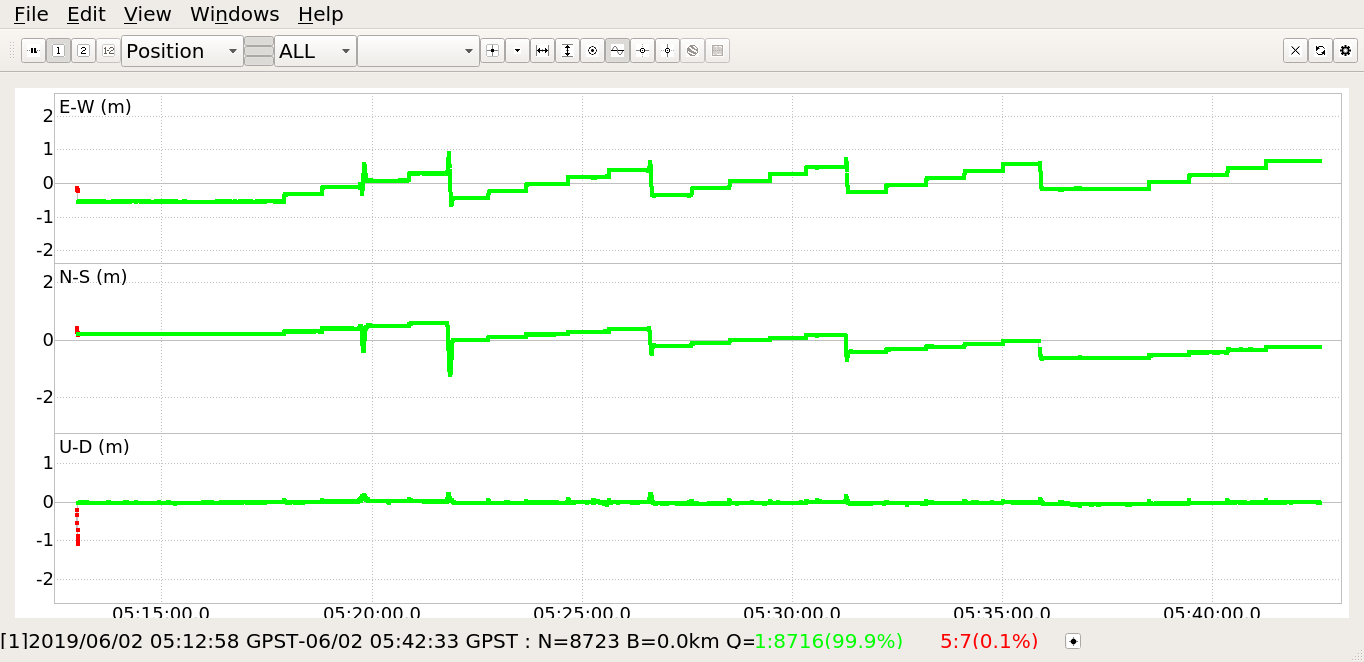
Here with RTKPLOT you can see the movements of the rover over the grid.

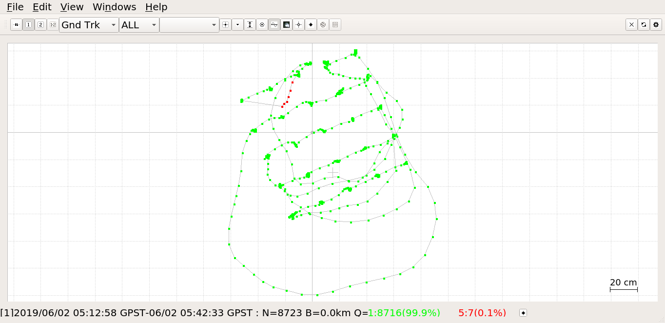
And here you can see the rover track. The wandering lines are me moving the rover between the peg holes.

I will share the distance between points and how that aligns with the grid later when I crunch the numbers.


…don’t worry, there is more to come

…and some of it might even be properly serious :nerd_face:

…in the meantime, keep a lookout for others posting here in the community forum about their experience with RS2.

14 Likes

Well thats some harsh treatment your giving here :sweat_smile:

1 Like

bump.

(added part iv to the 1st post)

2 Likes

Thats awesome results 2mm

1 Like

Yes, and I am going to show how those points line up with the grid once I brush up on my 3D calculus :roll_eyes:

The grid was definitely not level in that test, so I’ve transformed the points to X,Y,Z ECEF, then from ECEF to zero being the center of the point cloud, and now into inches which should match up with the grid spacing. I think I will try and work out a plane that fits the point cloud and then straighten (transform) it back to ‘level’. After that some meaningful numbers can result from it as in horizontal (X,Y) deviation, and vertical (Z).

3 Likes

@bide

my head hurts. :persevere:

2 Likes

Mine does too now. And apparently this is linear algebra, not 3D calculus.

Python with numpy helped me find the best fit plane:


credit to this link:

Now I have the equation of the plane:
0.559745 x + 0.797737 y + 0.000000 = z
and next is to rotate the point cloud to make it sit flat on the X-Y axis.

After ‘leveling’ the results, these are the errors observed from the 25 point grid survey in the 1st post, part iv:

name error x error y error z
cm cm cm
Point 1 0 1 1
Point 2 0 -1 0
Point 3 0 0 1
Point 4 0 0 2
Point 5 0 0 0
Point 6 0 0 0
Point 7 0 0 -1
Point 8 0 0 0
Point 9 0 0 -1
Point 10 0 0 -1
Point 11 0 0 0
Point 12 0 0 -2
Point 13 0 0 -1
Point 14 0 0 -1
Point 15 0 0 0
Point 16 0 0 0
Point 17 0 0 0
Point 18 0 0 0
Point 19 0 0 0
Point 20 0 0 0
Point 21 -1 0 -1
Point 22 0 0 0
Point 23 0 0 1
Point 24 0 0 1
Point 25 0 0 1

This test was done with a very short baseline with 2 Reach RS2. They were passing corrections over Wi-Fi at 1Hz with all constellations and all RTCM3 messages enabled.

3 Likes

grid test #3

  • Two Reach RS2 in RTK mode
  • Short-baseline test: ~10m
  • All constellations enabled
  • Corrections over LoRa
    • 18.23kb/s
    • 14dB
    • 915MHz
  • RTCM3 messages
    • all enabled (1006, 1074, 1084, 1094)
    • 0.5Hz on all, except 0.1Hz for station coordinates

This is the site. The sky view here is quite good. The grid and rover are on the ground which is not ideal because of increased multipath, but it is a stable placement for windy conditions like today (light wind at the surface and crazy upper winds).

Here you can see the rover sitting in the different grid positions over time. It moves along a row, and then back to the start and down a line, like a typewriter.

The ground track plot is not very attractive to look at, but there is some value in it. You can see the basic shape of the grid positions I used. There is one point with some single/float in red/blue. That is where I wasn’t thinking and put my hand over top and grabbed the antenna to move the rover. With it so low down, it is hard not to get in the way the sky view even when grabbing it from the side.

This is a screenshot showing some of the satellites that were in view.

This is the survey project output that was exported in CSV format.


(llh anonymized)

This is a plot of the output. Like previously, the grid is laid on the ground which is not level and it is not oriented in any particular direction. So the point cloud will have to be ‘squared’ to the axis as best as possible…

Errors:

x (cm) y (cm) z (cm)
0 0 0
0 0 0
0 -1 0
0 0 0
0 0 0
0 0 0
0 1 0
0 0 0
0 0 0
0 0 0
0 0 0
0 0 0
0 0 0
0 0 0
0 0 0
0 -1 0
0 0 0
0 0 0
0 0 0
0 0 0
0 0 0
0 0 0
0 0 0
0 0 0
0 0 0

This is a close-up showing that I should really have a short riser for RS2 to elevate it about 15cm (or 6in) and let the LoRa antenna stand straight, but ‘it works’ like this.

I’m sure some of you will be glad that I gave up on the format used for the 1st post. So am I :wink:

4 Likes

That is one Gangster looking tripod, gold chain and all :stuck_out_tongue:

5 Likes

Chappie just missing 1 antenna.

giphy

Getting bullied:

6 Likes

:sob::laughing::rofl:

2 Likes

*bump for a chart of errors that was added to the previous test (3rd grid test)


grid test #4:

  • same settings as grid test #3
  • Two Reach RS2 in RTK mode
  • Short-baseline test: ~10m
  • All constellations enabled
  • Corrections over LoRa
    • 18.23kb/s
    • 14dB
    • 915MHz
  • RTCM3 messages
    • all enabled (1006, 1074, 1084, 1094)
    • 0.5Hz on all, except 0.1Hz for station coordinates

This is also the same site as grid test #3, except there was an interesting obstacle nearby:

A large steel wall is a pretty good obstacle and generator of multipath signals, especially with corrugated sides.

This was a shorter test with only 9 points. Three furthest away, three in the middle, and three close to the wall. Here is the starting point which is the row that was furthest away:

And here is the row that was done closest to the wall:

For the survey project, default settings were used for ‘fixed’ points.


(llh anonymized)

These are the points after being run through the script that squares the plotted points to the XYZ axis. It is a bit hard to see the blue dots among the black grid lines:

This is the position log in RTKPLOT. You can see me bring the rover to the area at the start, and that I put the rover in the wrong hole once for a short time. Also there was a small offset in the Z axis near the end:

And here is the ugly ground track, also in RTKPLOT. There is not a lot of usefulness to this other than you see the rough grid spacing and it proves that the survey project point collection feature does a great job of turning these green splotches into well centered, cohesive points:

And this is chart of the errors which I think is a pretty good outcome, considering the conditions. I had to re-collect one of the points 3 times before it met the survey project standard deviation tests. It was one of the ones up against the wall. Other than that this was a pretty easy task with great results.

Errors:

x (cm) y (cm) z (cm)
0 0 0
-1 -1 0
0 1 0
0 0 0
0 0 0
0 0 0
0 0 0
0 1 0
0 1 0

I did this test beside the shipping container just to ‘try it out’ and these results were very encouraging. So I will do some more like this.


It has been a several days since this test was done, but I was struggling with the software script that automates the error calculation. There is 500 lines of completely unoptimized script cobbled together that finds the best fitting plane for the point cloud, then rotates the point cloud on one axis. This is repeated again, along with some centering loops. I want to stress that no scaling is applied though. The point cloud is just rotated to the most flat position on the XY axis and nudged into best alignment then the errors are calculated rawly. The physical grid I use is assumed to be made of perfect 1 inch (2.54cm) squares. So these results should be leaning toward the pessimistic side, and should match up just as if you were collecting points and comparing to your tape measure or laser or the corners of your tile. …because I don’t think many of us here are carrying a reflectorless total station around in our back pocket. :slight_smile:

6 Likes

Impressive. I actually didnt think it would perform so well. :grinning:

3 Likes

Yes, I was biting my nails on this one, and afterward I also took the rover by hand and did a quick walk around the steel container to see if there was a ‘bad side’, but I didn’t find any ‘bad side’. Like I mentioned, more investigation is necessary, but I was impressed too!

5 Likes

Very nice test Bide, as always ! You should add a decimal on your cm table, mm measurement is relevant on such baseline distances .
Also can you try the same with L1 only Reach to show the improvement ?

I like how @bide conveniently drug in that HEAVY shipping container full of RS2’s (or were they fortune cookies?) for testing multipath! Haha! ; )

2 Likes

I can probably do that when I get a bit more practice with this rig. The table just looked so clean with round numbers :smile: Also, these were just quick and dirty tests with no real planning / preparation / or second takes.

Now I have a system going, I hope to do some more interesting and meaningful tests.

In good time! After some more showing of what RS2 can do! As much as we with M+/RS/RS+ want to see that (and I haven’t even compared for myself yet), I think that there are lots of others out there where RS2 has just come on their radar as something that could work for them. They need to know if it can replace their older name-brand hardware or if they can save money by buying RS2 vs. renting equipment or hiring a contractor for mapping/surveying. I know I’m tolling the :emlid: company line with this rhetoric, but once that part is done, then we’ll solve the curiosities of the other Emlid owners (and myself too) :slight_smile:

Actually I have no idea what the container is all about. Don’t tell anyone, but I was tresspassing because that area was easily accessible and had a nice sky view (aside from sitting right beside the container). Of the couple of times I was there, I had a nosy neighbour interrogate me once :raising_hand_woman: and some really strange ‘night folk’ decide to hang out uncomfortably close to me and my gear. :zombie::woman_zombie:

3 Likes

You could do some tests with an RS2 and an RS + with version 2.18.0 and see the times it takes to fix. With my RS + it is faster to be fixed than with any other gps of thousands of usd.

1 Like

I have obtained precisions with points already measured 6 km from the base of only 4 mm

2 Likes