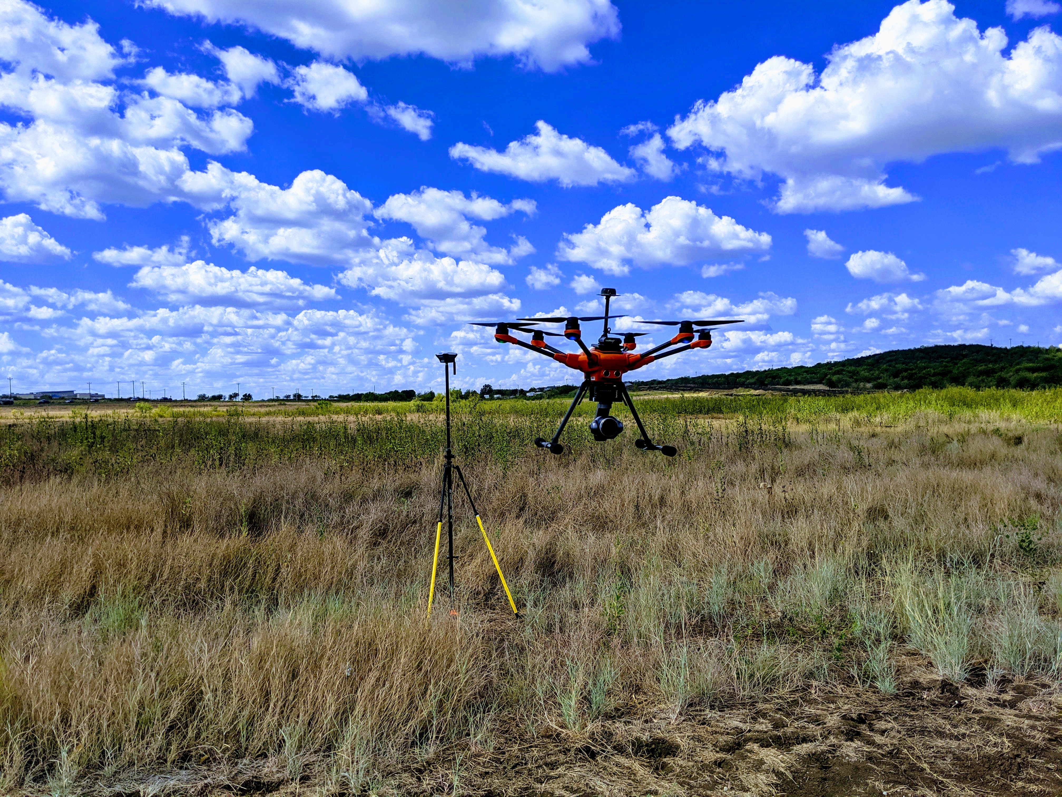
UAV mapping with a Yuneec H520, Emlid Reach RS+ base station and Emlid Reach M+ custom mount on the H520. While I have over 1,000 maps most of them have been with a Phantom 4 Professional with a very similar setup. This post is to show the diversity of the Emlid equipment and how a little ingenuity can create great results.
This project started several months ago and I have flown approximately 50 missions with the set up and can see that it is every bit as good as my other missions. I like to recommend the H520 because (1) It is a hexacopter which has rotor redundancy that can save you. I speak that from experience. (2) Being a hexacopter it is more stable and can fight adverse conditions much better. (3) The camera is at least on par with the Phantom 4 Pro which I believe is the best camera for mapping still to this day. Image quality, field of view and native distortion reduction is almost like they engineered it for mapping.
I had been thinking about mounting an M+ unit to it for a while, but the lightbulb went off when I found a li-ion battery with the correct specifications from one of my wife’s purses. It even had the micro USB connection and was the right size to mount the M+ and the Tallysman antenna on it.
I also wanted to bring up this project because others need to know that absolute camera position and GPS position don’t matter if you use (GCPs) ground control points. Not even the absolute positioning of my set up on the H520 (with 3M Extreme Dual Velcro) Makes any difference because I am looking for relative accuracy of the images taken In relation to each other. The GCPs do the rest of the work.
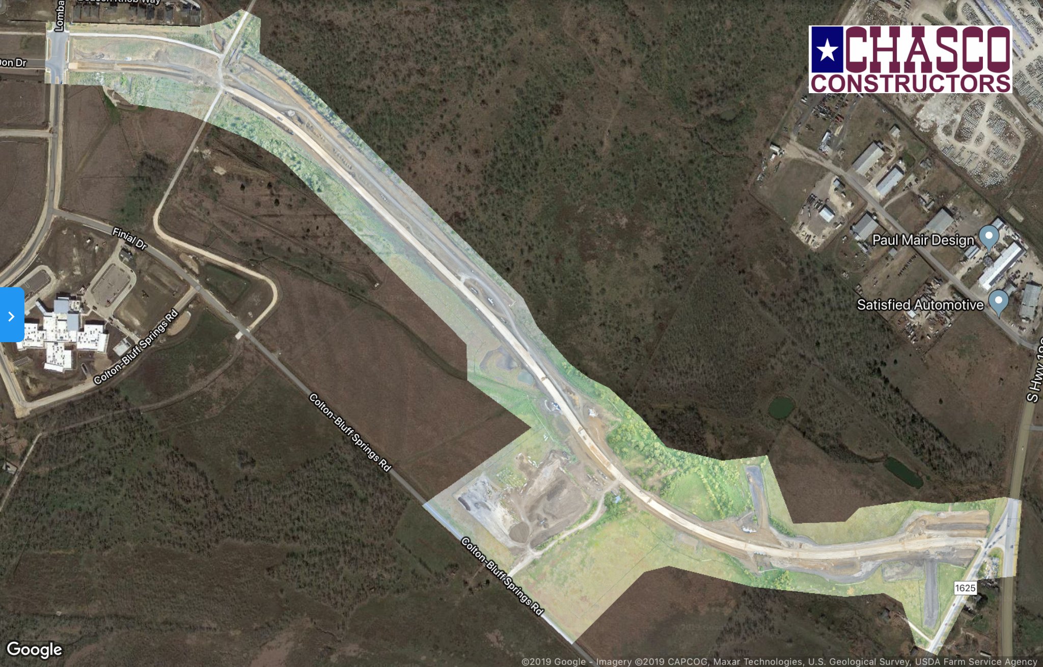
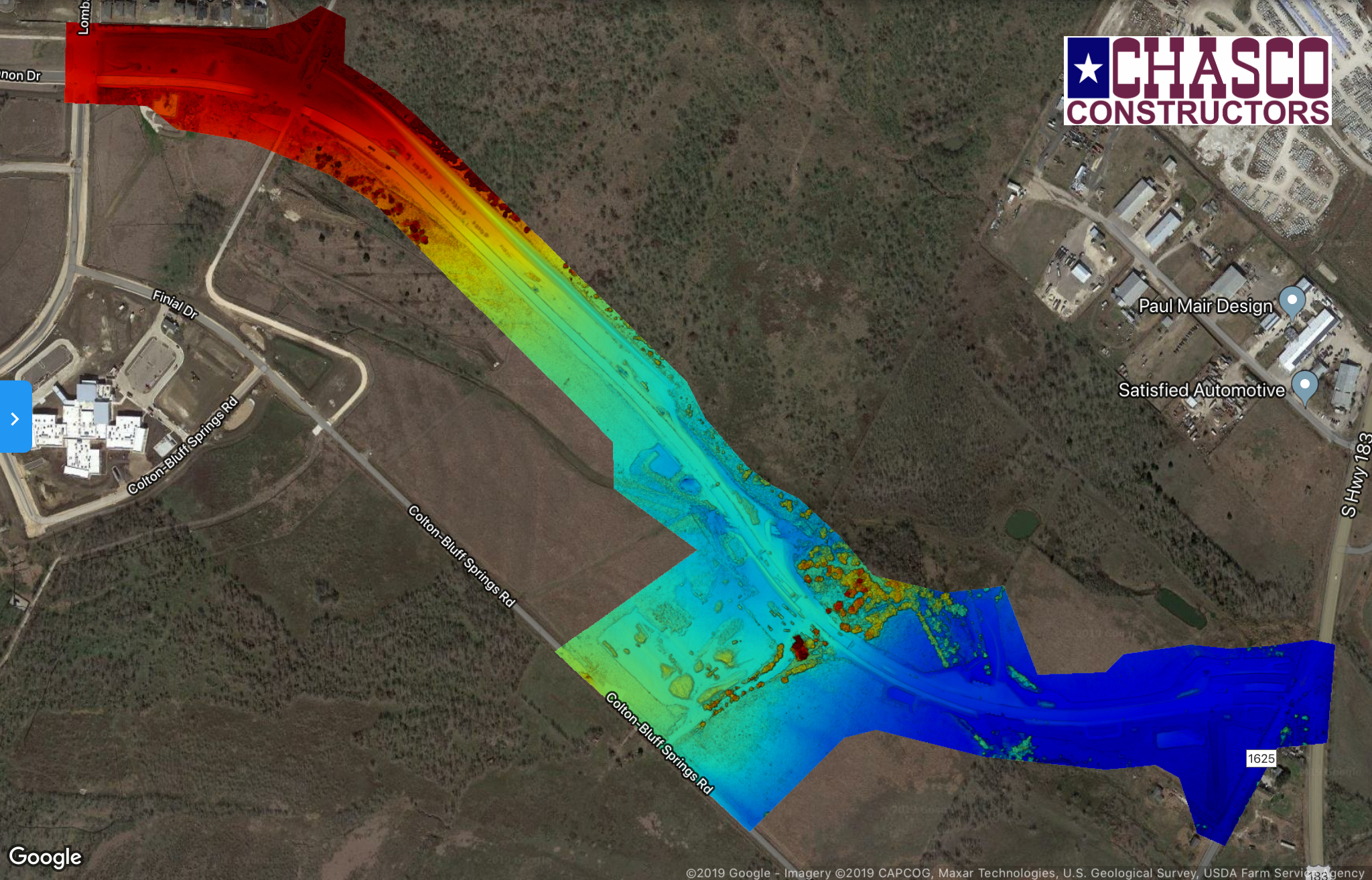
The mission was about 1-1/2 miles of roadway on 90 acres of land. It is a multi battery mission and takes about 30 minutes to fly. It was 3-1/2 miles from Austin-Bergstrom airport and required waivers with flight limited to 250 feet. There is about 100 feet of elevation change across the side so it’s not just your every day boring roadway.
With the Emlid kit I was able to reduce the number of GCP’s from 10 to 5. The RMSE’s on the ground control points averaged to 0.21 inches and the 5 checkpoints were 1.8 inches. Everything was processed with the DroneDeploy. While they do not YET support autonomous flight with the H520 you can still process the images.
Solid hardware, a little ingenuity and a good platform supplied very good results! I just wish I had posted this picture for the contest! Can I still get in…
I thank everyone in this community for their assistance and willingness to share!
I wonder about the antenna cable, is it ok to bend it like that? I always feel bad when I bend it with a 3 cm radius, but if your 0.3 cm radius does not affect it I might drop my worries… .
I think the recommended minimum bending radius is 5 times the cable diameter for coax cables. Good to hear that there is no effect, but maybe not something to repeat if you are not ready to take the risk. But it looks great nonetheless… .
Could you please post a scrrenshot of your observation data and the signal to noise ratio (with RTKplot, I’m interested in the SNR and cycle slips with your ground plane antenna offset)?
How do you get the camera-sync events from the camera to the M+? I have been looking into the Teokit, as it integrates really nicely, but the amount of modification required is a bit scary (even for someone used to building his own drones, including a lot of soldering)…
I have the same worries. If the cable maintains a circular shape and not an oval shape, then it should be fine and keep it’s low-loss properties.
When the cable becomes oval, then the impedence changes and when the bend is severe the RF can leak through the braided shielding on one side more than the other.
…but laboratory results be damned. If in practice it works, then it works.
You don’t. You shoot a checkshot and use the full GPX track to retag the images, not the events. The absolute position is then determined by the GCP’s.
I do 2-3 checkshots depending on if it is a multi-battery mission or not. Lift off, get to altitude, take a shot and start the mission. Do it again if multi-battery. One more at the end of the mission. Because those shots are obviously not part of the grid the are easy to recognize and attach to the track. The multiple checkshots helps me verify the log entry that I picked. Here again I am looking for cm relative accuracy of all the images in the flight and it wouldn’t work for what I am doing without GCP’s. Standard processing through RTKLIB and retagged with GeoSetter.