Situation:
Base is at static location ± 10 meter from rover “square”.
Rover will randomly move in a square of 4x4meter.
Desired effect:
At start i will “zero” the rover.
The rover will be static at the centre of the square.
I will save the current location.
Then the rover will move, and i want to know where in the square the rover is (desired accuracy ± 10cm).
I’m not interested in height.
i’m not interested in what the actual location of the square is.
I’m only interested in the position of the rover in this square.(and the displacement from the “zero”-point).
Question / issue
What output and method is advised for this project?
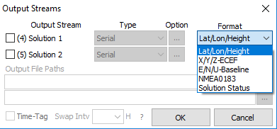
If i use the XYZ output i can’t directly use the X and Y numbers because this is relative to the centre mass of the earth.
But if i use the LLH Output it gives me degrees, not meter/centimeter.
Is there a “simple” way to convert the LLH to meter/centimeter. and would this work for my project?
once again, i’m not interested in where i am, only interested in difference between my zero-point and actual-point
I am assuming you will be staying withing range of wifi/bluetooth per your description of a 4x4 meter square.
If so try QField with rover RS+ streaming location via bluetooth onto device. You can set your project to any coordinate system you want and will project on fly from WGS84 Reach RS. You could try writing your own coordinate system file and bring into QGIS defining your own origin and parameters. But for your needs this should get you pretty darn close.
I think i found a solution, by converting to ENU (as @amadson mentioned) i can have my local XYZ plane.
The only thing i need to do is rotate around the U to get my desired X and Y vector.
code used:
public static void EcefToEnu(double x, double y, double z,
double lat0, double lon0, double h0,
out double xEast, out double yNorth, out double zUp)
{
// Convert to radians in notation consistent with the paper:
var lambda = DegreeToRadian(lat0);
var phi = DegreeToRadian(lon0);
var s = Math.Sin(lambda);
var N = a / Math.Sqrt(1 - e_sq * s * s);
var sin_lambda = Math.Sin(lambda);
var cos_lambda = Math.Cos(lambda);
var cos_phi = Math.Cos(phi);
var sin_phi = Math.Sin(phi);
double x0 = (h0 + N) * cos_lambda * cos_phi;
double y0 = (h0 + N) * cos_lambda * sin_phi;
double z0 = (h0 + (1 - e_sq) * N) * sin_lambda;
double xd, yd, zd;
xd = x - x0;
yd = y - y0;
zd = z - z0;
A long time has passed since this thread was closed. But I just wanted to leave a quick word on the updates. To operate your Reach RS+ now, you can use ReachView 3 app. It supports plenty of different coordinate systems, including UTM ones. It’ll help you work with plane coordinates in your project.