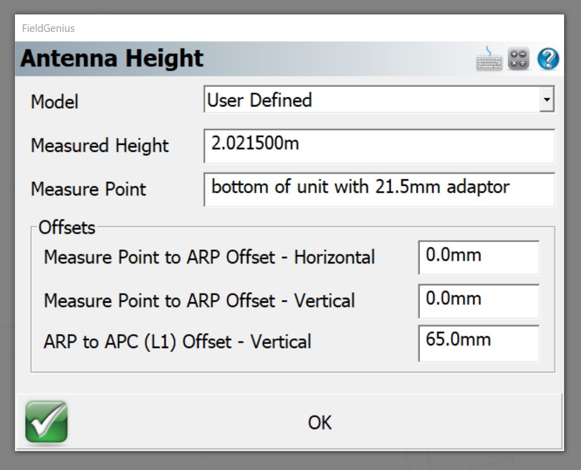
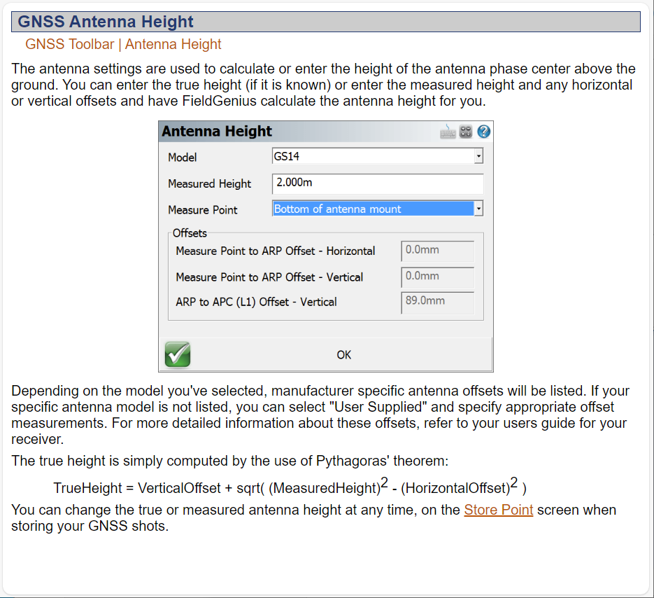
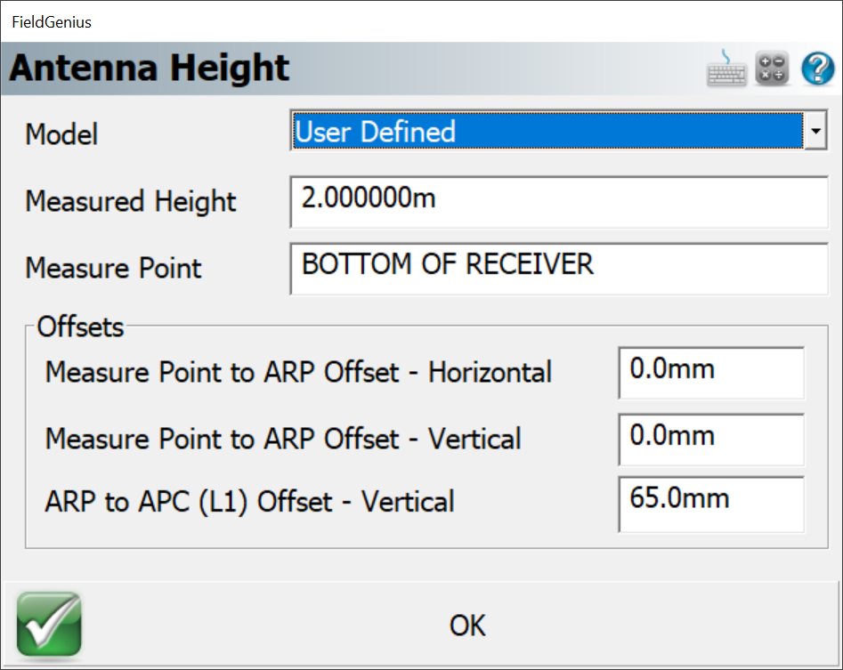
I know it’s probably too late after realizing this, but since Microsurvey had included a GNSS Profile in FieldGenius for the Emlid Reach RS, I had always assumed it took into account the APC and the thread adapter? I do not think it has. I had never specified the 65mm from the Antenna Reference Point (ARP) to the APC. (ARP to APC (L1) Offset - Vertical in the Antenna Height dialog). Just entered 2M for the rover pole. (never accounted for the 21.5mm thread adaptor either). (almost seems as if the 21.5mm thread adapter should be entered in the Measure Point to ARP Offset - Vertical field instead in the Antenna Height dialog?)
So this is all correctly taken into account for the RS2/RS+/RS3 in the future, might be a good idea to add this helpful information into the Integration section of the DOCS for Antenna Height? If coordinating a specialized driver (add Tilt capability also?) or GNSS profile with Microsurvey, may be a good idea for extra clarification. Also, since there are (2) APC’s L1 & L2 being a multi-band receiver, this may need also clarified? There is only 1 field for L1 in FieldGenius. Do we use just the L1 value or average both L1 and L2 and use that value???
i.e. when using third party antennas with the M2. What is the correct way to handle this?
If only one field to enter APC in software, (i.e. Microsurvey FieldGenius, Emlid Studio? PPK software?) but have both L1 and L2 measurement specs from Antenna Reference Point (ARP).
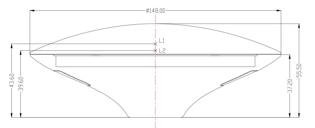
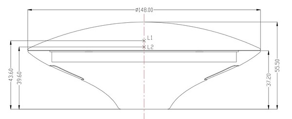
i.e. TOP106 dual band antenna L1: 43.60mm L2: 39.60mm
(41.6mm averaged)
What about multi-band antennas that have even more. i.e. L1 L2 L5 L6?
What do we enter when using the RS2/RS+/RS3 when using third party apps/software?
I know the ARP to GNSS antenna (Is this the same as APC? (electrical or mechanical?)) is 134mm per specs:
If it helps anyone in this discussion, I contacted ArduSimple.com about the Antenna Phase Center (APC) uncertainty. They also agree to AVERAGE the L1 and L2 when only one field available to enter this value in survey software. I’ve seen posts about just using the L1 value only? Obviously, the amount of error is pretty small either way? I will have to look into the antenna calibration files via NGS also if that helps. (The TOP106 (Sparkfun) is listed as calibrated).
I’m guessing that the 134mm for the RS2/RS2+/RS3 is L1 & L2 averaged as the specs do not show specifically the APC for each L1 & L2 individually???
My question to ArduSimple:
What Antenna Phase Center (APC) value would I enter into survey software that has only 1 field to do so? (i.e. Microsurvey Fieldgenius) This antenna has L1 (58mm?) and L2 (52mm?) measurements from the ARP to the APC. ( Calibrated Survey GNSS Multiband antenna (IP67) - ArduSimple) Are there further APC measurements for L5 & L6 also for antennas capable of this ? I do not see them on the label photo or in the specs or docs? Do you just enter only L1 or AVERAGE both L1 and L2 or all??? What do users do in this case where there are multiple APCs?
ArduSimple.com: When using external software to correct for antenna offset, unfortunately one one point can be introduced, in this case we recommend as you correctly mentioned the middle point between L1 and L2. Note that the error of the receiver is larger than this distance, thus the error introduced by this is very small. To solve this issue, you can also introduce antenna calibration files directly into the receiver, in this way the receiver can individually compensate for the different measurement points between L1 and L2.
I put out a question to Microsurvey and below is the response from them. @julia.shestakovaWhat would be good to know though for FURTHER EXACT CLARIFICATION, is the 134mm Antenna Phase Center (APC) (from bottom of unit (Antenna Reference Point (ARP) to APC) an AVERAGE of L1 & L2 of the RS2/RS2+/RS3? Or is the ARP to APC to L1 ONLY?
Microsurvey response:
Tim,
1 - Only the L1 offset is required. But we have not worked with the M2 models before, only the RS and RS2. So after entering in that L1 offset, I would check against known points to confirm if it’s correct.
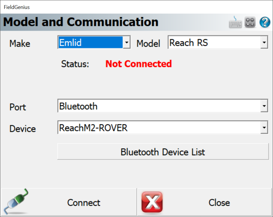
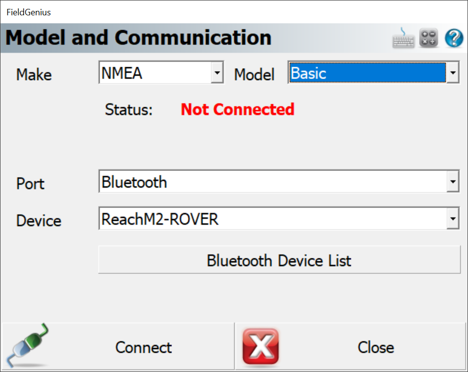
2 - Because these are untested M2 models, you can try either the Emlid - Reach or NMEA - Basic for the Make - Model. Again, untested, so cannot say for sure which will be better. But APC settings are not included in the Windows version for the Emlid - RS driver. (The Android one does, but it’s for the RS2 model)
3 - The antenna height won’t reflect the offset values, so just enter what the pole measurement is to the bottom of the receiver or measure point. (whatever that L1 offset is referenced to related to the pole).
4 - I don’t believe you need to do any average, just the L1 offset is OK. But since this is the M2 model, I would recommend testing it thoroughly to confirm.
As a reference, we have a couple of articles here that might help if you use the RS or RS2 models:
I have a couple Emlid M2’s and TOP106 multi-band antennas.
So the points I am testing are correctly measured, what exactly should the settings be in FieldGenius if ONLY one field to provide the "ARP to APC (L1) Offset - Vertical" is available but the antenna has BOTH L1 & L2? L1: 43.60mm L2: 39.60mm. Should we use L1 or AVERAGE both L1 & L2: 41.6mm? Same if using a L1 L2 L5 L6 multiband antenna in the future? Average or use just L1 ONLY? Not exactly clear in the help file.
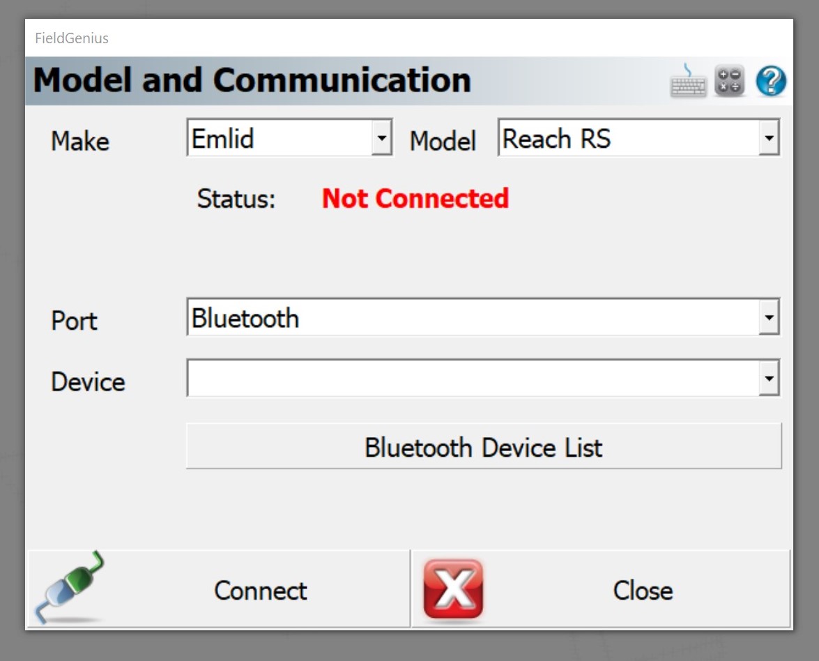
For the MAKE, is it OK to select the Emlid Model: Reach RS and enter correct Antenna Height settings or do we need to select the NMEA Make? Wonder if the Reach RS model specific driver has built in APC settings that may interfere?
Rover pole from tip to ARP (bottom of TOP106) is typical 2m pole.
I notice when entering the ARP to APC in the field entry, the Antenna Height in FG just stays at rover pole height of 2m? Doesn’t reflect / add the additional height to the APC? So not sure exactly if calculations going on in the background?
Are the settings correct below? Or should ARP to APC be the average 41.6mm? Or should the “Measured Height”: just include the total of 2m pole and 43.6mm L1 (or average?) = 2.0436mm and do not enter anything for the ARP to APC? Not sure what the other 2 offsets are (Measure Point to ARP Offset - Horizontal & Vertical)?
Hope this helps anyone else needing clarification. Further inquiries and final response:
My question to Microsurvey:
Thank you very much in this somewhat confusing subject. I think I follow you pretty well here.
I put out a question to EMLID to see if the 134mm offset they provide for the multiband L1&L2 RS2/RS+/RS3 is actually an AVERAGE of L1 & L2 or if in fact just to L1 only. Either way, it is the APC we will use per your docs and Emlid. Hopefully I get a response for those models if in fact AVERAGE or not.
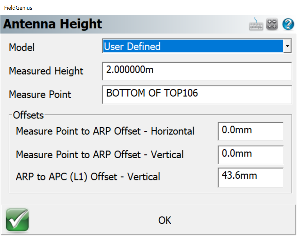
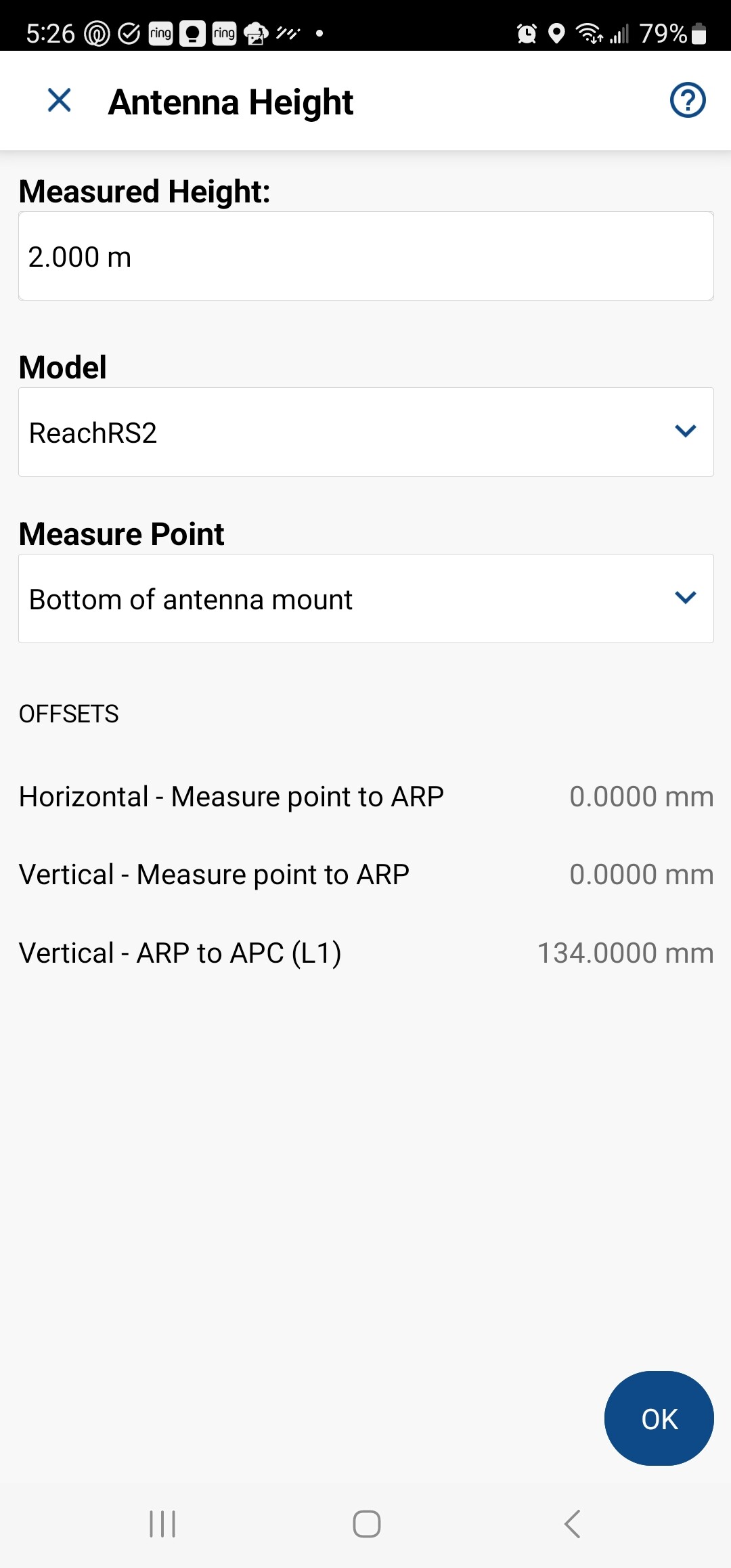
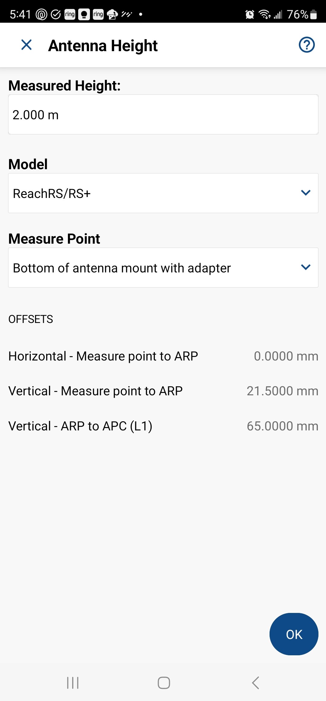
But to keep things ABSOULUTELY simple so I grasp what you are saying, is the below settings correct then for a SINGLE BAND L1 Emlid RS/RS+ receiver using just a standard 2m rover pole (tip at ground point to bottom of receiver ARP) and with Emlid’s 65mm L1 offset they provide? I will test obviously against known points, but to start, this seems to be the correct way to set it in FG? Correct? Just want to makes sure I shouldn’t be entering the TOTAL of pole and APC of 2.065m in the Measure Point field and leaving the ARP to APC (L1) field empty.
For further reference, attached Screen Shots of FieldGenius Android built-in profiles for Emlid with default settings (but changed Measured Height for typical 2m rover pole).
Sorry, it’s been so quiet here. I’ve merged your two threads since they were quite on the same topic. Let me try to answer your questions.
Emlid Flow uses the physical distance between the bottom of the receiver and the bottom of the antenna, while L1 and L2 are Phase Center Offsets. In most cases, using the physical distance wouldn’t affect the resulting accuracy, as they are somewhat similar and lie in line with the accuracy in our data sheet. However, for more precise PPP observations, it might be important to work with the phase offset.
Using our multi-band receivers with third-party software, we also suggest using the physical distance instead of the average of the Phase Center Offset values. However, there are third-party apps that can use ATX files. In that case, you can get those files from the antenna Antenna Calibrations page of NOAA. These kinds of apps will get all the necessary values from them.
But for third-party applications, please don’t forget to add the pole height and the thread adapter too, if you have one.
Regarding our docs, I see your point! We will think about how we can clarify this information!
The RS/RS+
L1: 65mm APC
Phase Center Error: ± 2 mm
Multi-band helical GNSS antenna
L1: 0.035 m
L2: 0.037 m
Phase Center Error: ± 2 mm
RS2/RS2+/RS3
L1: 0.1349 m
L2: 0.1371 m
Phase Center Error: ± 2 mm
RX
L1: 0.1471 m
L2: 0.149 m
Phase Center Error: ± 2 mm
Regarding the Antenna Radius, as far as I know, the radius of the “antenna” is used to calculate slant height when installing a base station on a tripod. This is why the software wants it. Most likely, you need the receiver radius in this case.
You can find these values on the drawings of RS/RS+, RS2/RS2+/RS3, RX, and in this thread for the Multi-band helical GNSS antenna.


 Movie CLIP - Zoltan Meeting (2000) HD")