


Can you get the RINEX logs from the REACH base to post process if is in RTK mode? or do you need a third unit over another known point?
Larry,
Good morning.
Thanks for getting back with me on the plug configuration for the antenna.
The cables are also sold on Amazon. I am thinking that I will not need a cable longer that 24" so I can tie it down to the tripod or the rover rod.
I think that I will also need radios at this point so the two stations can communicate and do corrections on the fly instead of post processing.
Otherwise, post processing will work as well.
Are you on Facebook or LinkedIn?
Larry,
I am Ray Smith in Facebook and from West Monroe, LA
Larry,
I have contacted Tallysman and they recommend two antennas:
TW 3400 and TW 3710 which say works even better for RTK stations. Both have domes covering the antennas. Here is a link to both:
This one receives GPS + GLONASS AND Galileo signal as well:
http://www.digikey.com/product-detail/en/tallysman-wireless-inc/33-3710-01-01/1526-1019-ND/4862791
This one receives GPS + GLONASS ONLY:
http://www.digikey.com/product-detail/en/tallysman-wireless-inc/33-3400-01-01/1526-1016-ND/4862788
Since Emlid will soon have a firmware upgrade so that it can utilize the Galileo constallation it would be worth the extra $10.
These cost $20 to $30 more that the TW2405 you have and are using.
Thanks for your help.
1 Like
These are the antennas that Allen at Tallysman is recommending if you also want to use the Reach stations future ability to use the Galileo signals and will need in RTK work. This is copied from our email this morning:
Hi Ray,
Since you won’t be placing a cover over the antenna, I recommend you consider the TW2710 or the TW3710 for use in your RTK system. The TW3710 is the best choice for use in an RTK system as the feed from the antenna exits from the bottom of the antenna. With the TW2710, the feed exits the side of the housing which can affect the Phase Centre Variation of the antenna and the phase linearity of the antenna. If you prefer to use the TW2710, I recommend that you route the cable beneath a ground plane as close to the housing as possible so as to hide the cable from the patch.
As to your ground planes, they don’t need to be that thick! All that is needed is an RF reflective material which is plane. Aluminum foil on a flat surface works very well. Some people just cut circles out of paint can lids. The 126mm diameter is fine. We don’t recommend going any larger than that.
(My ground plane is 10 mm thick)
Hopefully this will be useful to the community.
2 Likes
Ray
I was thinking that Galileo satellite system was not very large but I just read that they plan to have 18 satellite by the end of the year and a total of 30 in 4 more years.
I’ve also read that the more satellite systems an antenna can receive the less sensitive they are overall.
Larry
Larry,
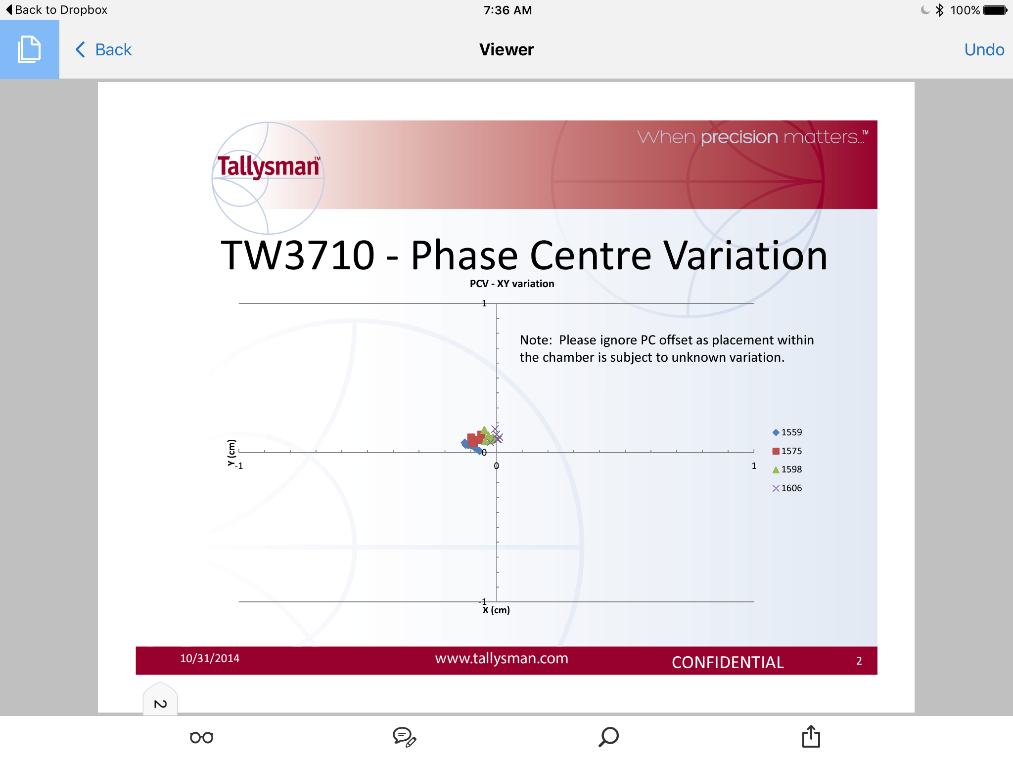
The chamber tests that Allen sent me were don on 3 GPS, GLONASS and BeiDou and did not include Galileo. The pattern on the chart shows a very tight signal pattern on all. I wrote Allen back and asked him is they had a test that included Galileo but have not heard back from him. I cannot upload the PDF copy he sent to the forum because that file type is not allowed. He sent me tests on the TW2706 and TW3710 and tells me that the TW3710 antenna is used in surveyor RTK equipment.
Since Galileo will be in an upcoming Firmware Reach upgrade, seems like a good idea for me because our part of Louisiana has pine forests and Galileo, according to my surveyor, puts out a stronger signal.
Here is a screen shot of the main test results page for the TW3710.
1 Like
Ray
This kind of information is very valuable. I’m glad you are going right to the experts.
Looking at the paths that the Galileo satellites will be on, I’m not sure how good they will work for my area.
Larry
Larry,
Essentially, I will be prepared for the future.
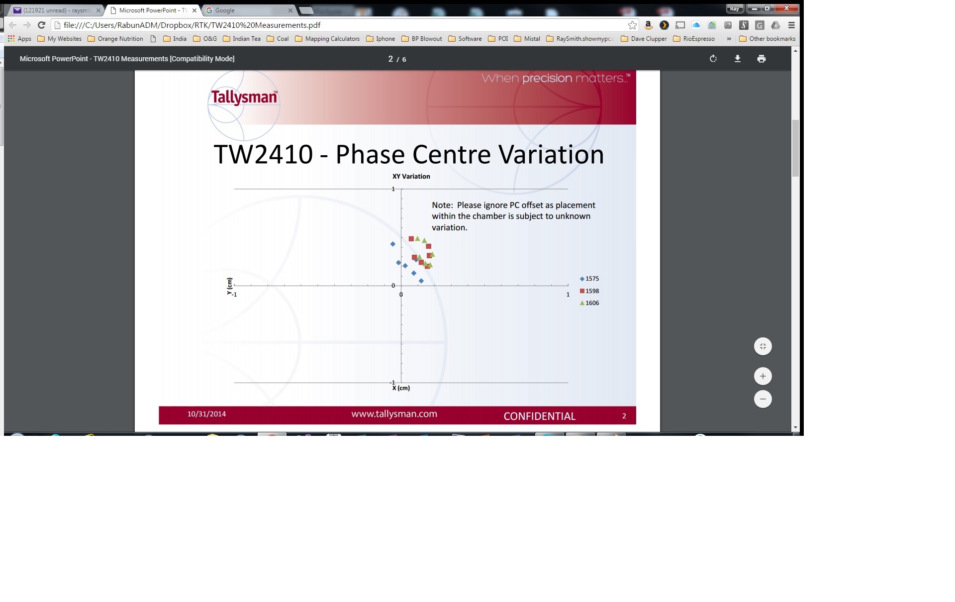
Allen with Tallysman sent me this on the TW2410 which has identical response to your TW2405. I am not much help with the attached chart and therefore am relying on Allen’s advice on this one.
My only issue with the TW3710 is the hook up to the rover. Since it would be the center and the rover pole has a threaded connection, how do I get the antenna in the center and still attach the ground plane to the rover without some kind of bracket? I will see what Allen recommends to solve this.
I don’t see much reason to get in a hurry as the kit comes with an antenna to get me started.
I like to solve problems right the first time when possible.
Ray
For using the 2405 antenna on my octocopter I will 3D print a mount that has a ground plane and an enclosure for the antenna. I’ve used aluminum foil tape for a light weight ground plane with very good success.
My brother does the 3D printing with Nylon filament so I can have a light weight, very durable mount.
Larry
1 Like
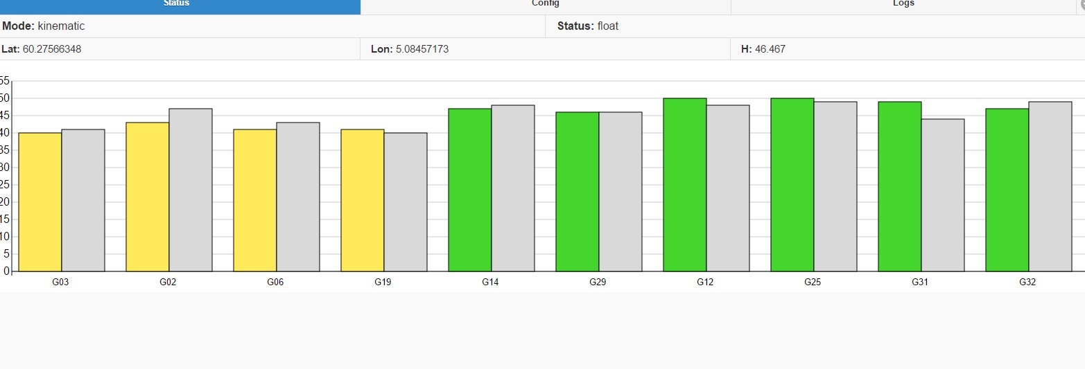
So…struggled to get a fix all day. Got only float, but very accurate float for 10-15minutes
Had 5-7 sats between 45-50 for both rover and base, but no fix. Used gps, galileo and glonass, i`m not sure if all three should be used…
The weather was cloudy.
2 Likes
Trying to comprehend the meaning of “integer ambiguity”. Directly translatet to norwegian, this doesn`t give any meaning.
But i think i have far clue whats going on. So, would i be right to say that float is good enough for me?
I only need about 10 +/- cm accuracy when position is relative to base station, and not absolute.
And this is fun too. Cm accuracy with cellphone by the ende of 2020. Hehe
I found this looking for info about integer ambiguity.
Update.
Can confirm that this is working and this is so cool. You are being redirected...
I also now see that my previous “problem” with offset is taking care of.
With autocad i can import siteplan with all know points and if i for some reason cant get a fix at some point, placing a fix as close as i can get and maually measure on the fly in autocad, how far the point actually is. That is awesome
When i testet gps with mock location, i was worried that the internal gps on my phone would mess it up.
But i got my coordinates confirmed to be right, showing me values from my rover and not my phone.
When rover was turned of i would get coordinates way off from where i actually was. When rover turned on, after a couple of seconds, coordinated dialed right in on the spot where rover was. Watching the dot on autocad dial right on the spot was just wicked. That is so impressive
I use Samsung S5 with gps mock location enabled, Bluetooth gps app and autocad360.
3 Likes
Update:
After adjusting for glonass and other minor tweeks, reach got fix much faster and in areas where i before couldnt get fix.
Ref. this post - GNSS live map - Planning best reception? or avoid a bad time - #4 by bide
But as you can see from the background, status where showing or not showing anything. Troublshooting for this i found out that reachview is out of date, running verion 0.2.2.
Hopefully this fix thing right next time.
3 Likes
Hi!
Could you try clearing your browsers’s cache?
It can be easily done with Chrome’s or Firefox’s dev tools. The cache will be disabled with the tools open only, however one refresh with the tools open should be enough.
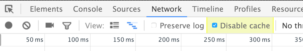
In Chrome:
The Chrome DevTools can disable the cache.

Right-click and Inspect Element to open the DevTools. Now click Network in the toolbar. Finally, check the Disable cache checkbox at the top.
In Firefox:
Follow this guide, go to settings(Gear tab), advanced settings and set Disable cache
Control + F5 will clear the page’s cache as well
I didnt get any error yesterday, after upgrading from 0.2.2 to 0.3.2. So its all good her 
Hi luke,
That is awsome, but does the topographer receive fixed coordinate? How to connect topographer to lefebure?
Finally some major progress.
It`s all related to the above info and my goal to use Reach for survey anything.
I finally got some time to test my gear and also got my self a provider for correction. Local ntrip from Kartverket
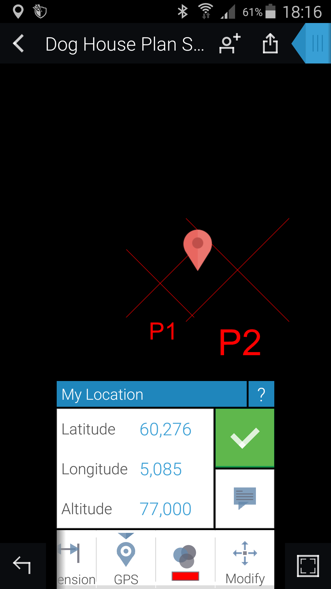
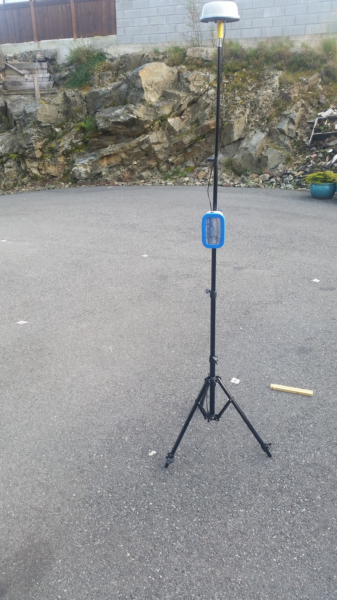
My goal is to open my workdrawings with fields coordinates and info on my autocad360 app on the phone and survey points to the ground on our contruction site, all this with Reach in a plastic lunch box ![]()
So, this time i made a square mark in arhicad, it`s 2000x2000mm and is geolocated with local reference as you can see from the image below. Once this drawing was done and some other points where placd, i saved this as .dxf and open it up in autocad360 to check everything looks ok.
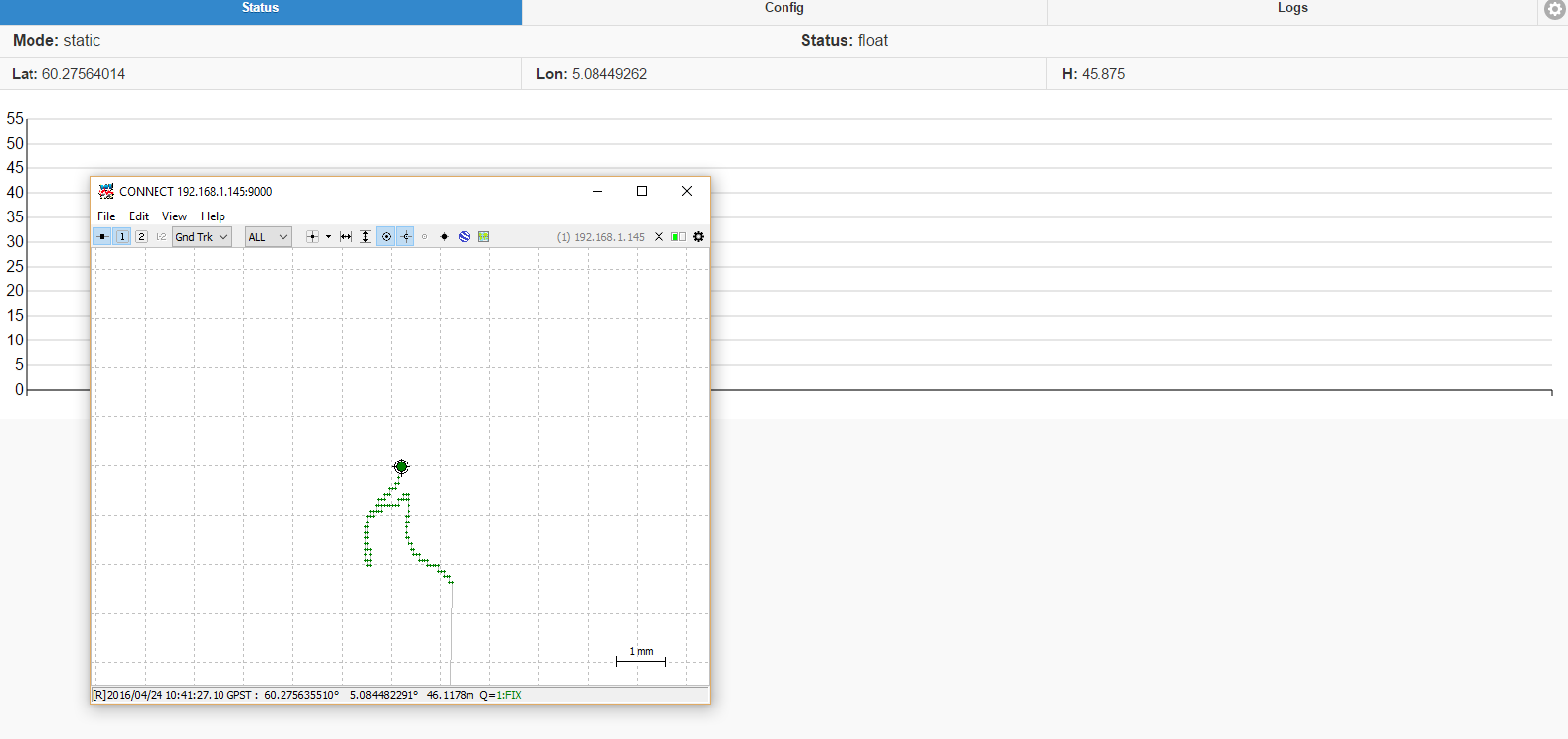
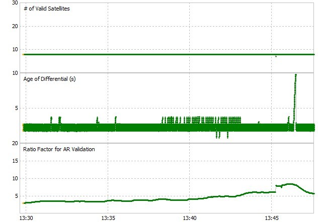
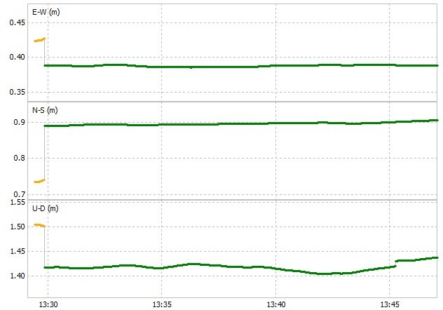
Next thing was to connect reach to ntrip which provide VRS baseline and cm accuracy. My location is not that good so i did expect the worst. After some adjusting with the setting i got up grey bars, Yay. Now i had to wait about 10min with pretty accurat float before fix nailed it and stayed fixed for over an hour continuesly, Awesome. Se pics below.
With bluetooth enabled and connected with GPS bluetooth app, i open up autocad360 to manually set the reference point. I know my dxf drawing was geo refered by i didnt wanna hasse with that now. So with known point i set my location and can see my self walking around in my drawing and the 2x2m square drawing to stake out. I made a screen record and uploaded it to youtube for you to see. You can see how a adjust scale in autocad to precisely navigate the rover over the point. Now, the ground was not level and rover was mounted on a tripod which made the stand not perfect vertical, so some inaccuracy in this metod but my point is proven. I think i got the most of it and all i can say is that i am impressed by the level of accuracy from Reach. Im very saticfied and i`m gonne work on routine and workflow to make this my favourite tool.
I have one obstacle left, and that is to find a way to know when reach is in fix/float mode, because with autocad open i can`t see is the coordinates is fixed or not. Any idee here?
I did read something in docs that green light flashing on reach meens fix, but i think mine is blinking green in float and fixed mode. Anyways, here are som pics.
You can see from the image where i have marked the ground while surveying in the youtube clip.
Link to youtube: RTK cm accuracy with ntrip provider and Autocad360 - YouTube
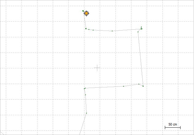
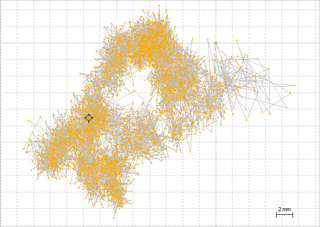
On the image above you can see how rtkplot is logging my movement when trying to marke my 2x2m square drawing.


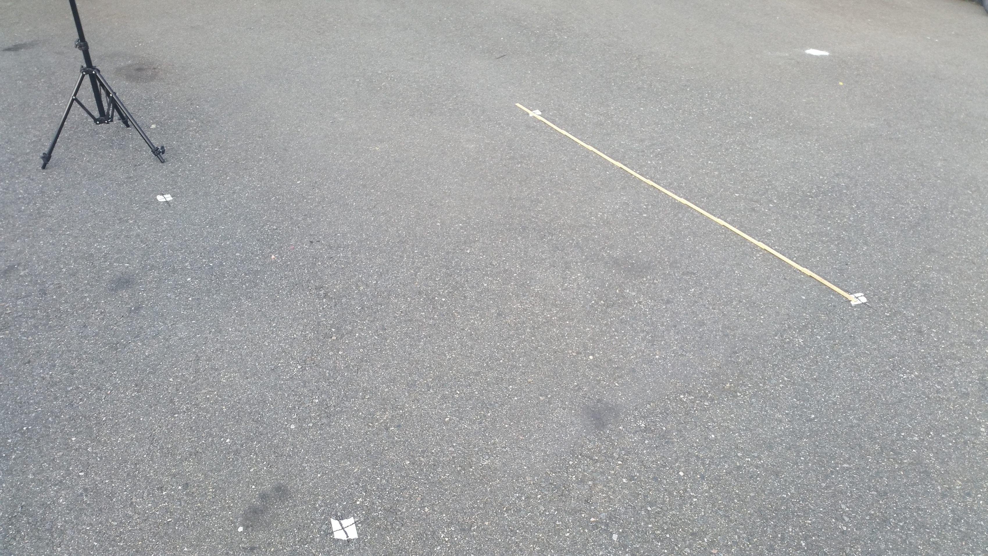
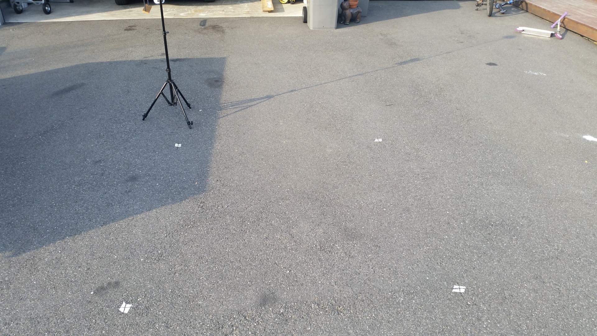
Final image shows 2x2m square marks on the ground. I`m satisfied
4 Likes
A final note about autocad360 that is worth mentioning.
1 Like