


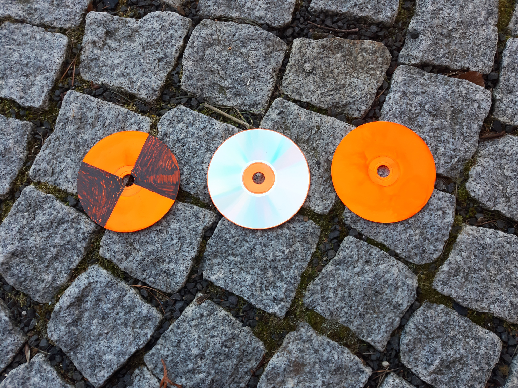
We use old CDs secured with nail with washer. Metallic side up we use as GCP for thermal cameras (they show as -30°C or less since they reflect sky).
10 Likes
I like this. again a smaller area, as small as you can easily recognize I think is the best because it localized is your vision to the center.
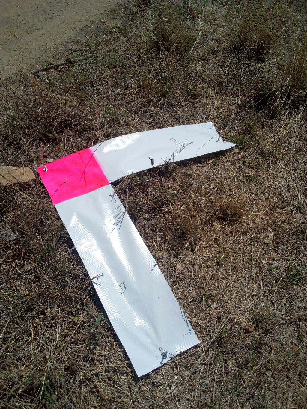
Very close to my method when I am marking surfaces of that nature. You might find that the White markings are more visible if you put down a scratch of black paint before you put the white or outline the white with the black. manhole covers are my favorite. I just have to be careful with them because they can change elevation somewhere around paving time.
I do, if needed
1 Like
What precision do you require from your work?
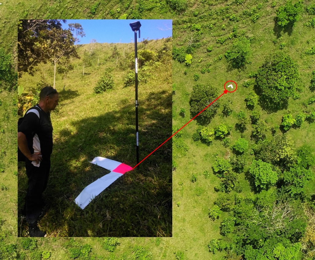
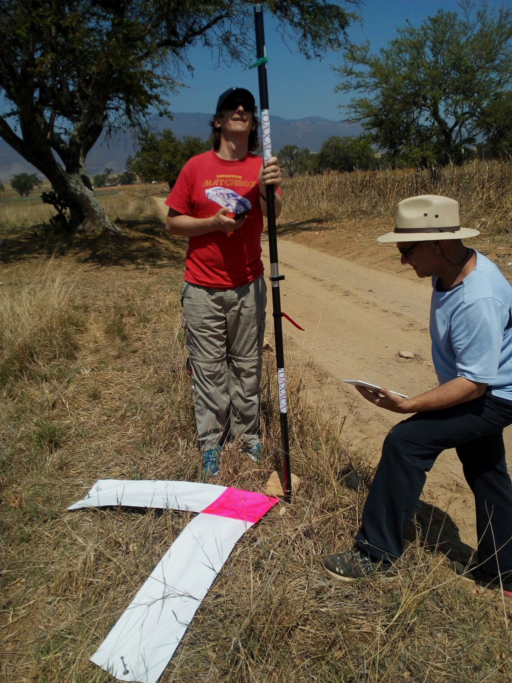
I see the rover rod seems offset by 5 cm on both vertical and horizontal axis in relation to the tip of marker?
This is an example of what I referenced previously. Because of the way photogrammetry and GCP’s work several centimeters will make little to no difference. In the overall model. We have to switch gears from survey to mapping and photogrammetric modeling.
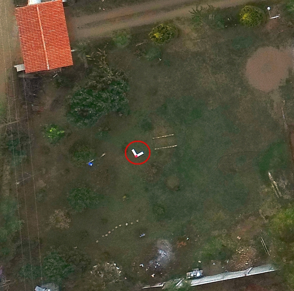
We use this pattern for TXDOT panel control. Because it is also visible from planes.
Well, depends on your purpose right?
If you are mapping 5 sq km, sure 5 cm of doesnt really affect much. But then again, if you have to do is place the rover rod right, then why not?
Also, don’t you deliver the error to the client as well?
On the other hand, for the volume measurements I do, 5 cm error would be huge.
How about running a map twice and running a cut/fill scenario and stockpile report between them and let’s see what kind of deviations you see? Then run it a third time purposefully missing the tags by a couple of cm and run the tests again. Whether it’s 5sqkm, 50ac or 5ac. I am the customer and know what the numbers are and the significance of them.
That being said, yes of course we locate the exact center with a level road and try to get close to the center when tagging, but trying to hyper-analyze part of the process that makes little to no difference on the final model is fruitless. You’d be better off learning more about flight patterns and processing.
1 Like
Thanks for the hint. Unfortunately, I have posted photos showing situations before we were to measure the points. Of course we measure exactly at the tip of the marker. We want the best possible accuracy.
2 Likes
Of course we are all here for best accuracy, but I want to help people understand the process and what it is capable of. I have produced over 400 maps and have never comprised my survey process or drone pogram SOP, but I also know when I am spinning my wheels.
Accuracy can be expressed both relatively and absolutely. Generally, if your flight was planned well for sufficient overlap for the terrain/site your model will have a very high relative accuracy. Your flight planning and image collection is far more important to the quality of the final model than the inclusion of GCPs. GCPs don’t improve the quality of the reconstruction they really only affect the alignment of the reconstructed model to the intended reference frame or its absolute accuracy. When we talk volumetrics and distances, these are all relative measurements and can be relatively accurate within your model regardless of GCPs.
If one needs a quality volume measurement one should focus more on the imagery. Adding obliques in combination with NADIR with lots of overlap is time better spent than running around with a pole and laying x’s.
2 Likes
Thanks for the input, much appreciated.
How would you qualify the error of and the confidence in the volumetric measurement? Through GSD, GCP rms, or something else?
Error is typically 1-3 times your ground sampling distance and varies across the model. The better the model was constructed the closer to 1:1 that ratio can become on all axis. Pix4D has a very good article on how they assess error for volumetrics. Better explained by them as has some substance in there…
To verify relative accuracy for any model you would still have to verify the scale of the reconstruction was correct between two known points in the model and on the surface. To generalize if I shot a project at 1.5cm GSD in good conditions I would be confident that most distance measurements would have an error ranging from (1.5cm x 1) and (1.5cm x 3) or 1.5cm and 4.5cm. If I planned flight correctly and provided quality data, I would be confident in an error closer to my average ground sampling distance. To prove, I would have to measure known points on surface. If your scale is close to 1 you done good.
Field measure and compare. You will find about a 2 to 3% variance, but if you actually count the trucks you will find that it is much closer than any field measurement you can do.
You’re spot on my friend. All gcps do is locate and align the site to whatever control was used. In our position we occasionally have coordinates from the surveyor or the engineer that do not truly line up to State plane so you cannot do a simple export transformation. relative accuracy is what 90% of the people need that I have seen on these forums. I am trying to get absolute accuracy that I can stakeout to and in my experience hyper-analyzing the gcps makes very little difference because the best I can get is plus or minus 2 to 3in on staking out a model regardless of how much I scrutinized the data.
1 Like
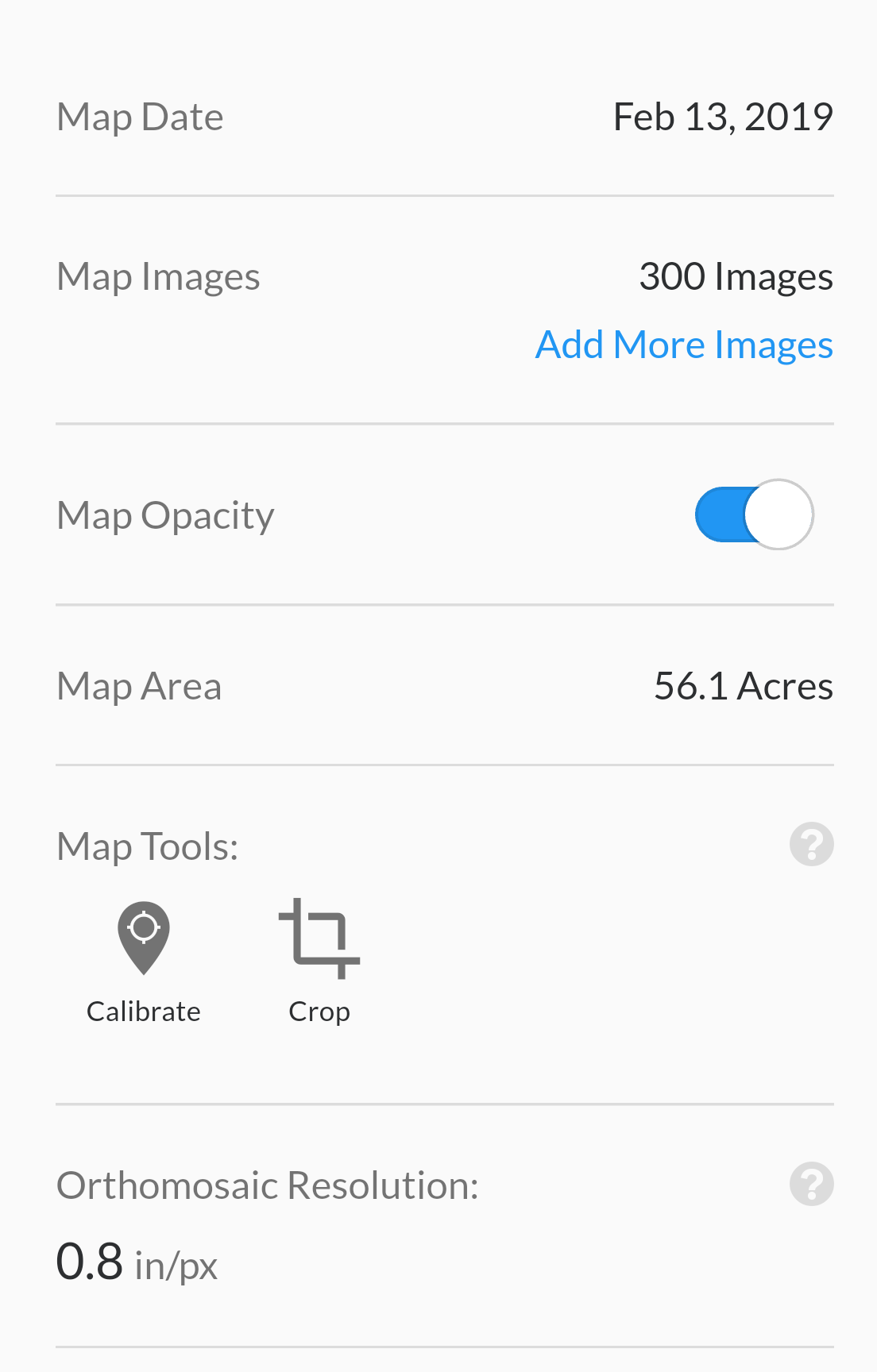
What is your ground sampling distance on these models typically? At 300-400 ft flight altitude on a DJI Phantom 4 Pro I can expect between 1-1.5in ground sampling distance. Provided that the error is typically 1-3 times the ground sampling distance, your at best 2-3 inch during stakeout makes sense as the best you will get. In other words you cant be more accurate then your resolution. Good stuff.
1 Like
I typically fly between 240’ and 270’. I really don’t like going above that so I have plenty of batteries. GSD is usually 0.7-0.9in.
1 Like
From what I have seen in Photoscan/Metashape, this is not necessarily the case. Given small enough RMS values (high confidence), the GCP’s are used to force the scenery into place.
I have seen local clusters being modified in the Z-axis i.e. when using GCP’s.
Also, you can do camera-calibrations using GCP’s. There’s a clear difference here in calibration parameters between no GCP’s in use, and GCP’s in use.
I notice you seem to use DroneDeploy, so maybe they use the the GCP’s different. I have never played with GCP’s in Dronedeploy due to the “payment-wall” of their business model.