What is the minimum size (pixels) for automatic detection?
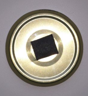
I tend to use much smaller targets. Below the latest example for a low costs student project in a wet peatland where the target should survive mowing. It was nailed on a piece of wood which was put 50 cm into the peat.
What I ask myself is whether the targets give meaningful information about the accuracy of the orthomosaic since they are totally different from the environment I’m mapping.
I could not finde any pixel size information in the Metashape documentation. Are there any experience values?
I only habe the experience that white paper is a problem because the reflection outshines the black marks on a DIN A4 paper.
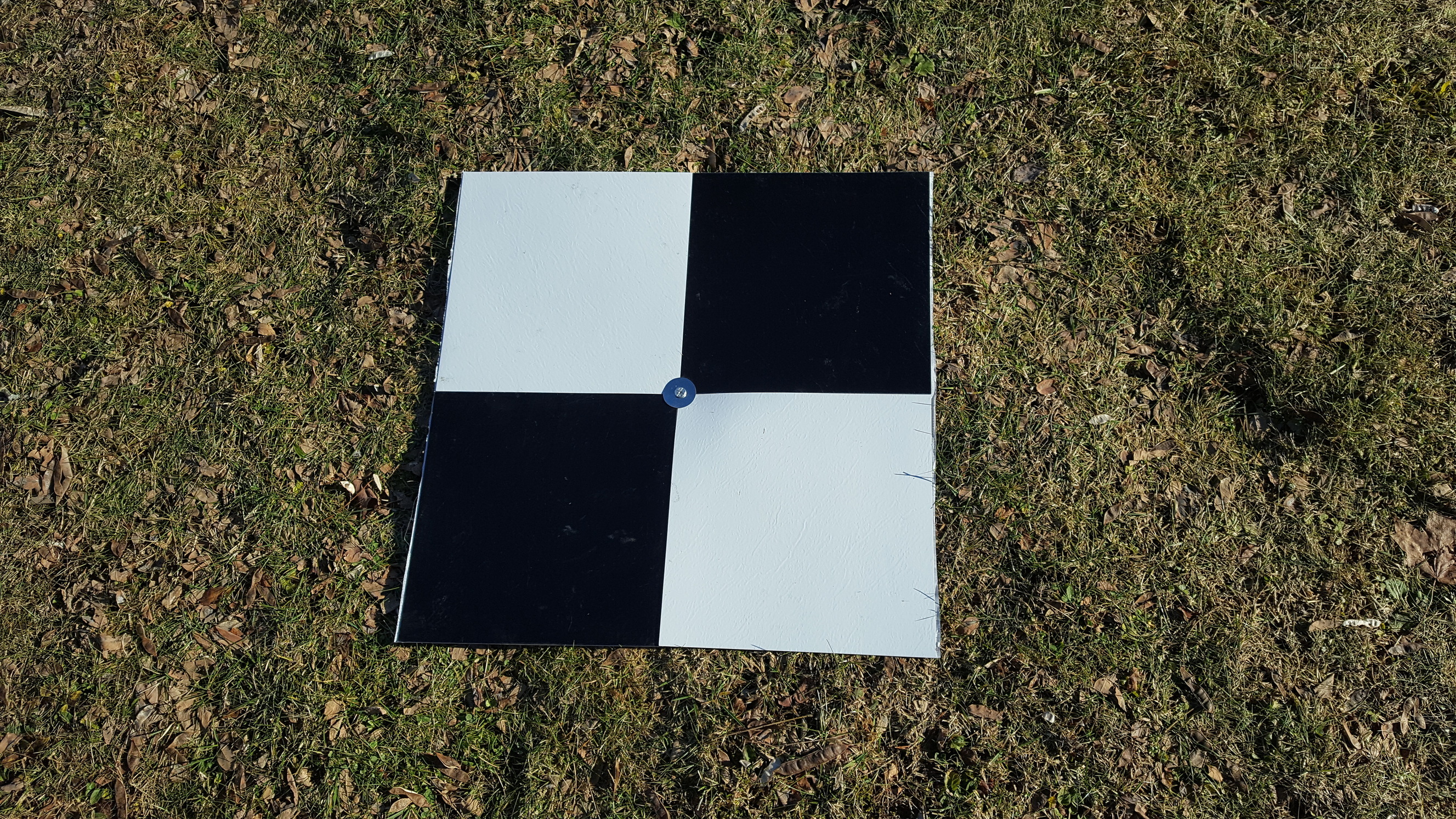
I was using a black and white vinyl, which I was lucky to find in the local store. 25*25 cm square. Total size of GCP is 50 cm to 50 cm. Works good.
On the glaciers we use special GCPs, that are made out of fabric. They are washable and have quite durable coating against water and dirt. Colours are orange and blue. On a glacier everything is black-and-white, so such colours are easier to spot on the images. We added grommets on the corners and in the center of GCP. By using screws or just nails we can fix it in place and the grommet in the middle is easy to measure with the pole.
Hm, it seems they have taken the numbers out for the v1.5 documentation. In the older documentation it said that the inside circle should be no more than 20 px in diameter.
In the new docuementation they have also added a few disclaimers, namely that the targets will be sort of big, if they should be detectable at say 10 cm/px GSD.
Your RMSE when processed.
I was told that any other than flat surfaces for GCP would be more likely to introduce additional errors.
Would be nice with some numbers. Then I wouldn’t have carry around heavy boards
I don’t know for now, because still haven’t processed any model with those GCPs. You think it will differ from black-and-white? I am checking the position of the marker on every picture and correcting if it is erroneous.
I think color is irrelevant, especially if the GCP marker placement is done manually in the software.
What I would worry about would be the curvature or or unevenness of a GCP. Not sure how well photogrammetry software copes with such changes. If it averages it for the GCP, that could give an error of several cm on the Z axis.
Since photogrammetry software doesn’t know, how a GCP looks like, I think it just treats them as all other objects on the picture. Unless you are using in-built marker recognition, which I don’t use.