


Can some one help me with those (Parameters)
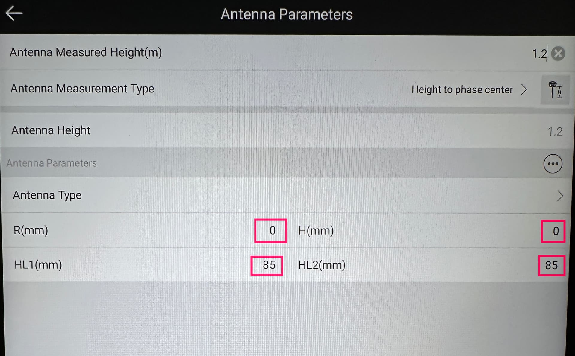
needed to setup RX with SURPAD4.2?
Thanks Bryan
The Emlid drawing below shows 145mm from the mounting thread (ARP) to the GNNS antenna level (which I assume they mean from the Antenna Reference Point (ARP) up to the Antenna Phase Center (APC)). Not sure as Emlid isn’t using this standard terminology in their documentation or illustrating it exactly in their drawing specs? Is this to the mechanical or electrical center also???
Being a multi-band receiver, like other antenna manufacteres have, Emlid should also be specifying BOTH L1 and L2 APCs, but they do not.
Is the 145mm an AVERAGE of L1 and L2 or is it L1 only? What is L2’s APC??? No idea.
Now as for the NOAA calibration data… is the 147.1mm for the GPS L1 BAND??? The 149.0mm for the GLONASS L1 BAND??? Or vice versa??? L2 APC’s???
Seems to me, if we are going to be absolutely precise, the very point of where the APC should be exactly known and how it was exactly derived. Shouldn’t be ambiguous.
Good luck as Emlid has not provided an exact accurate answer to this mystery yet for any of the receivers.
Clear as mud. ![]()
I agree with you to a point concerning the precise antenna phase offsets, but let’s get real here.
At best with a minimum of 5 minutes occupation in either a local RTK (radio link) or with an RTN statewide network or local NTRIP, you’ll only see 2-3 cm horizontal and 2-5 cm vertical accuracies on continual re-observations.
5mm is nothing compared to the scenarios above. To obtain any kind of 2-3 cm accuracy in both horizontal and vertical components , requires multiple observations on multiple days and also raw data to process (that the RX doesn’t have) to verify the accuracy.
Understood.
Either way, just seems data is inconsistent or missing from the specs / drawings to refer to which leaves one guessing?
The RS/RS+ (simple)
L1: 65mm APC
Ant R:
Phase Center Error: x± mm
Multi-band helical GNSS antenna
L1: 0.035 m
L2: 0.037 m
Ant R:
Phase Center Error: x± mm
RS2/RS2+/RS3
L1:
L2:
Ant R: 63.7mm
Phase Center Error: x± mm
RX
L1:
L2:
Ant R:
Phase Center Error: x± mm
To expand further, what exactly in each field should the OP plug in without guessing? Hmm?
Example. Missing antenna Radius though:
https://cdn.sparkfun.com/assets/b/4/6/d/e/TOP106_GNSS_Antenna.pdf?_gl=1*850r1a*_ga*MTk1Njk5MzQ1OC4xNjk1NDUyMDA5*_ga_T369JS7J9N*MTY5ODAxNDczNS40LjEuMTY5ODAxNDgzOS40OS4wLjA.
I wish I had the time you do Tim to research such a fascinating subject. I appreciate your time in this subject as I would suspect most haven’t considered this issue. Thanks Tim !
Well, just one of the issues I have is what kind of realtime PP algorithms are used in the positioning engines in the software, i.e. what kind of GNSS chip is used in the RX, for that matter for the rest of Emlid’s products. I suspect the Ublox chip is used but I haven’t seen any documentation on this.
The user doesn’t even know whether if both phase center offsets are used in the computations or even if the Glonass weird ambiguities are even allowed for. I’ve seen no documentation on any of this.
So… for the face value of any Emlid product, it’s a low cost entry level receiver for wanna be photogrammetrists, wanna be geodesists and wanna be professional land surveyors.
There’s nothing wrong with any of Emlid’s products. I suspect the chip used is a Ublox derived product, however there’s not much on the actual Ublox algorithms published by them let alone a true rinex converter that is published by Ublox that I’m aware of.
Emlid has taken a commercial GNSS chip and has made a good entry level, low cost product. I wish I had thought of the business plan years ago when I saw Ublox’s first single frequency chips. However, it is what it is.
HA! Actually like you and many, I really don’t have the time either! ![]()
Either way, yes, Emlid makes GREAT products!
The difference between the L1 and L2 maybe even be less than the phase center error in the end anyways.
But… I still think this data should be known regardless. Mainly to alleviate any sort of “guessing”, which I’ve seen in other posts.
I mean really, we’re about precision and accuracy here… so why skip over something like this even if its thought to be non-important or critical?
Maybe this data can be updated in the specs hopefully? I know, I know, Emlid wants to keep things simple to avoid confusion… but still think it should be included in the technical reference for each product.
![]()
Hi @yousif4000,
Bryan is right. The best way to get these parameters is the Antenna Calibrations page of NOAA.
@timd1971 I’ve tried to answer your questions on this topic in another thread. Let’s continue the conversation there!