Note that this thread was originally made because I was concerned about the accuracy of tilt compensation in the RS3. As it turned out, after discussions in the thread, there are no problems with the accuracy of tilt compensation in the RS3. The problem I had encountered was a sort of ‘edge effect’ that related to the rover rod being fixed in place for too long so that the IMU was not getting enough motion to do its magic. I considered deleting the thread and replacing it with a concise version so as not to discourage anyone from buying an RS3, but it seems people wanted to keep the thread. So I am leaving the thread intact below for reference.
I recently purchased an RS3 for the specific reason that it was marketed as having tilt compensation. Marketing claims that attracted me to the RS3 included the following:
“The IMU-based tilt compensation in Reach RS3 enables you to make measurements with up to 60 degrees of tilt while still staying within 20 mm of accuracy.”
The stated accuracy in the datasheet for the RS3 is as follows:
Tilt RTK + 2 mm + 0.3 mm/°
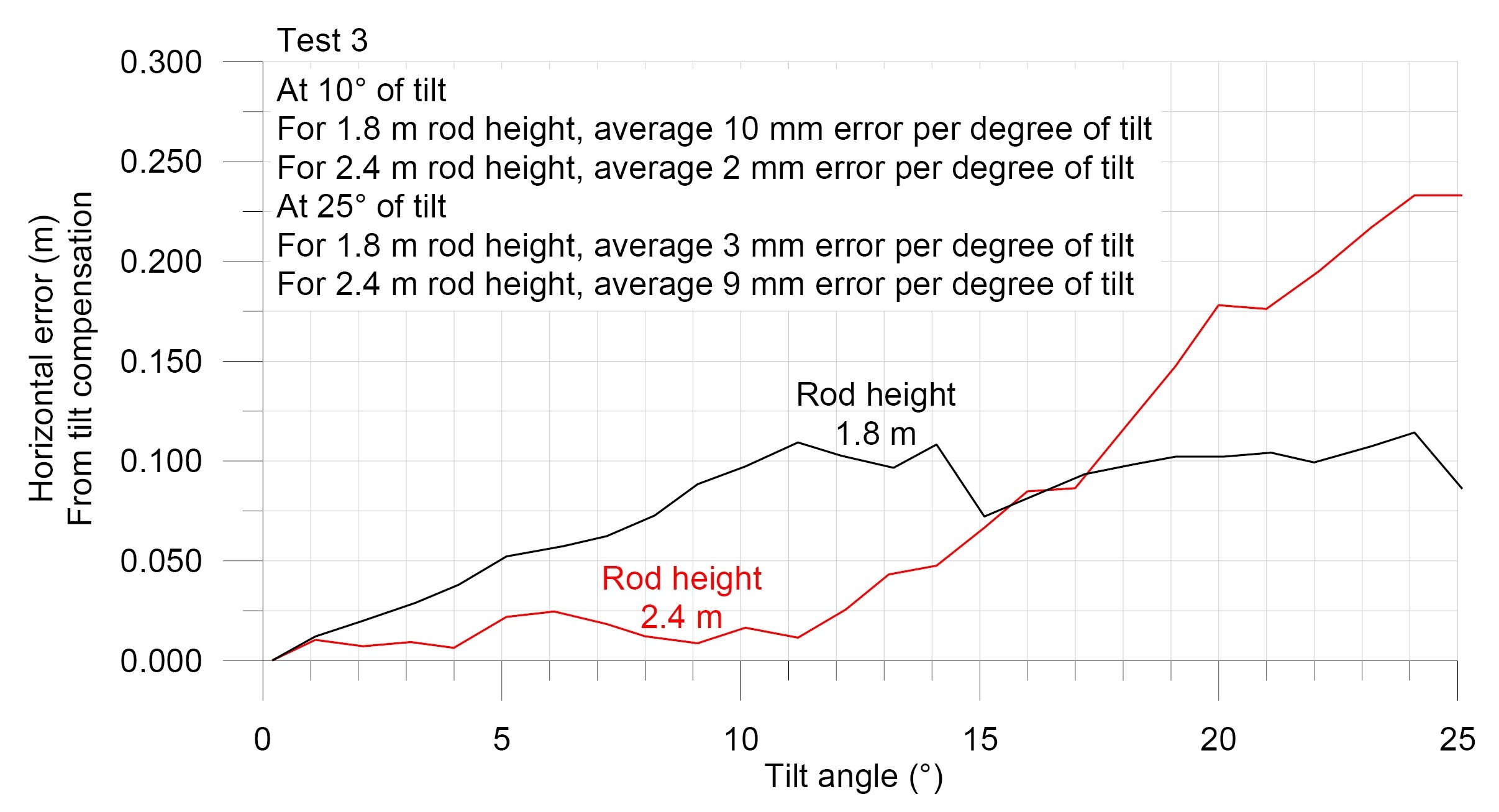
To date, I have not found any way to test the RS3 that produces evidence to support the accuracy spec in the datasheet. My findings show mixed results, but with the horizontal accuracy of tilt compensation in the range of 2 to 10 mm per degree of tilt (i.e., errors 1 to 2 orders of magnitude larger than reported in spec sheet). The figure below shows horizontal accuracy of tilt compensation tested with two different rod heights.
RS3 is brand new… I am sure they will get it worked out and seems @igor.vereninov is helping you with that? I would personally rule the issue out and send out a replacement fast to see if it resolved the issue and go from there…especially being a new product launch. Unless they are replicating the same issue on their end of course.
What gets me though, is there are SOOOOOO many tilt capable receivers out there these days for years… i.e. lower priced chinese ones and obviously much more expensive big dog Leica ones etc. Seems this feature would be nailed down pretty well by now.
Emlid has such a nice spot in the market with their excellent product design, lower cost and Emlid community and great support.
Having been beta testing the RS3 for months, I cannot for the life of me recognize your testing results.
Are you absolutely sure your tilt-correction is applied at all?
Just the other day I took the RS3 out to a job-site and under very difficult receiver conditions applied ~45 degrees and tilt on 20+ points and did 3 rounds of observations over 3 hours. Even on the worst worst points I would get 4-5 cm, and on the best of the worst we are talking 2 cm.
On the ones with better conditions, accuracy when used as a checkpoint in photogrammetry would come back as below 1 cm (average of the 3 points observation).
To me this sounds more like an unfortunate RMA case than false marketing claims?
…or even possibly user error even as thorough as they may be… it is still possible to make some sort of mistake that reflects badly down the line. Not saying this may be the absolute fact… but I think this needs to be looked at more and figured out before claiming it’s all just bad… which I am sure Emlid is or will do, being a new product release.
Great research and reports Joe. I’d consider getting in touch with Emlid support . I’ve had the M2 and RS2 the last 2 years, no problem at all. If if I had any issues, I could have found a solution on the forum or support.
They have good products, maybe I’ll get an RS3 in the future
My tests involved shooting a point with rod fixed into plumb position using a quick-release tripod. Before shooting the point, the rod was rotated 360° about the vertical axis to verify that the bubble level is adjusted properly (i.e., bubble stays perfectly centred within the circle). The point was shot with IMU on and IMU status as “Tilt compensation is ready”. The rod was then tilted through a range of tilt angles up to 25 or 30°, with IMU status indicated for every measurement as “Tilt compensation is ready”. IMU was then turned off and a shot was taken with rod plumb. The tilt-compensated rover coordinates were then compared with the coordinate obtained with the rod plumb.
If anyone can suggest a better testing procedure, I would be happy to give it a try. This seems like a perfectly fair test of tilt compensation to me.
Your testing method is obviously fine… but lets just say maybe it is a faulty unit? I.e. not calibrated exactly from the factory? Is there any sort of calibration sheet provide with each new calibrated RS3 like Leica provides with their precision equipment? That might be something Emlid needs to consider to rule out warranty claims if not.
Give Emlid a thorough chance to help. I mean really, you got the attention of @igor.vereninov
I did not receive any calibration sheets. Unless there is a way to verify that tilt compensation performs up to spec, I must conclude that either the unit is faulty or the spec is overstated.
I would certainly welcome instructions on how to quantitatively verify that tilt compensation is performing to spec.
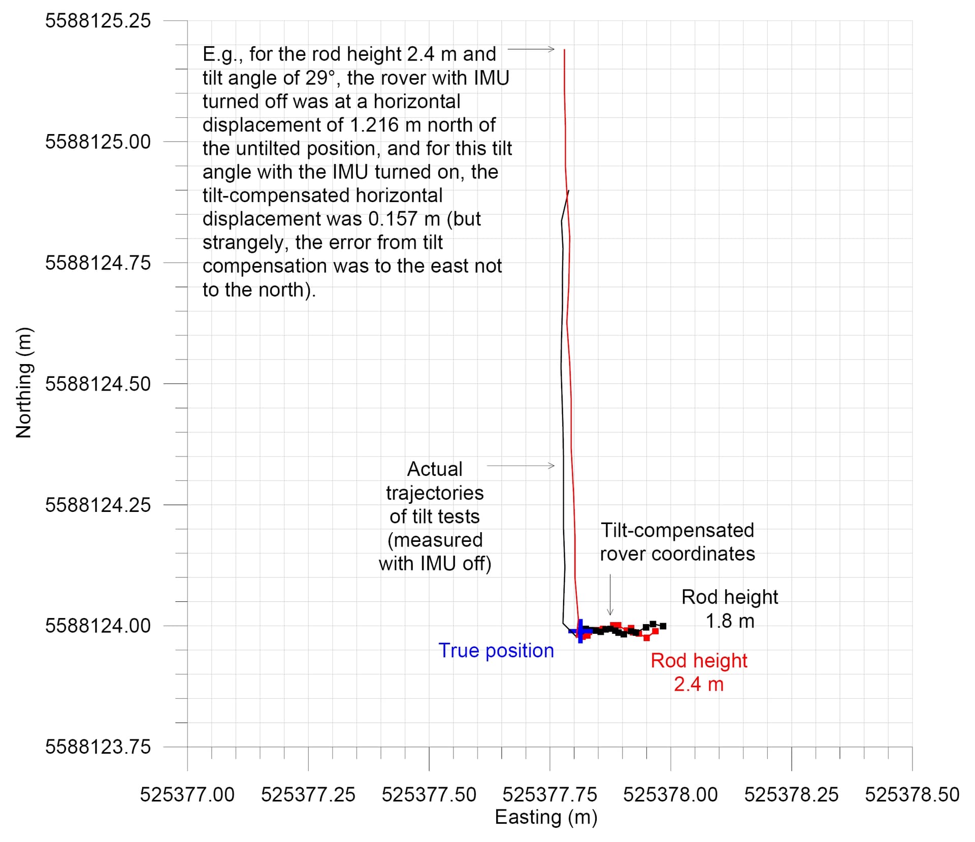
Yes, I am absolutely sure that tilt compensation is applied. The tilt compensated rover coordinates are absolutely closer to the true coordinate than if tilt compensation was not used. For example, see the map below. For the rod height of 2.4 m and a tilt angle of 29°, the actual receiver position is off the true coordinate by 1.216 m (to the north), whereas the tilt-compensated position is only 0.157 m off (to the east).
You might want to double check EVERYTHING coming from the corrections also? Correct Antenna Height? Same coord system? Physically measure baseline with other methods since short distance?
Also, rule out any excessive RFI or EMF (i.e. high voltage powerlines, welding machines, close by?) even though the new RS3 6DOF IMU may not have a magnetometer to introduce interference?
I’m not very knowledgeable concerning the RS3 tilt functions yet… I’m wondering how are the tilt angles determined during the tests. Does the RS3 indicate the tilt during the measurement?
If not, a simple protractor could be used attached to the rod with a plumb bob (robert, from us old surveyors) and use the string for the measurement of the angle. A bipod (tripod) would be needed for stability in measuring the vertical at all four cardinal directions.
If the software is indicating the tilt, this would be a good check for the internal imu and software also.
There’s something wrong in either the software or imu .
Bryan, the RS3 rover output includes a tilt reading reported to the nearest tenth of a degree. The IMU status also reports the tilt reading in Emlid Flow.
I’d do what @EBE111057 mentions and further test your actual tilt angles starting with direct 90 deg zenith directly straight up Z and plumb. Compare your physical angles with what is showing up in Flow, then go from there.
Wondering if it isnt correctly calibrated at the factory, everything is just gonna be off from there out no matter what ya do.
Emlid may need to provide some sort of calibration printout from the factory as proof? Kinda like what ya get afyer you get your front end alignment of a vehicle? Yeah, extra BS for Emlid… but just an idea.
I’m wondering if using a tripod when measuring with a tilted rod with the IMU function on, is causing the problems. I think I have read with other systems using the IMU function, that it needs to see movement, however slight from hand holding in order to make the necessary tilt corrections. I might have it wrong, but just throwing this out there. Hopefully, Emlid will provide you with the answer.
Thanks timd1971. I did a check this evening to verify that the rover is performing well without the IMU. I laid out two points on a curb separated by a measured slope distance of 0.997 m (measured with multiple tape measures). I used a 4-foot spirit level to make it so the two points are in a level plane.
The RS3 rover measurements with IMU off for the two points yielded a slope distance of 0.994 m and an elevation difference of 0.002 m. So that at least tells me the RS3 is working well and getting good corrections from the base. There are no major EMF sources nearby that I could see when I looked around out there today.
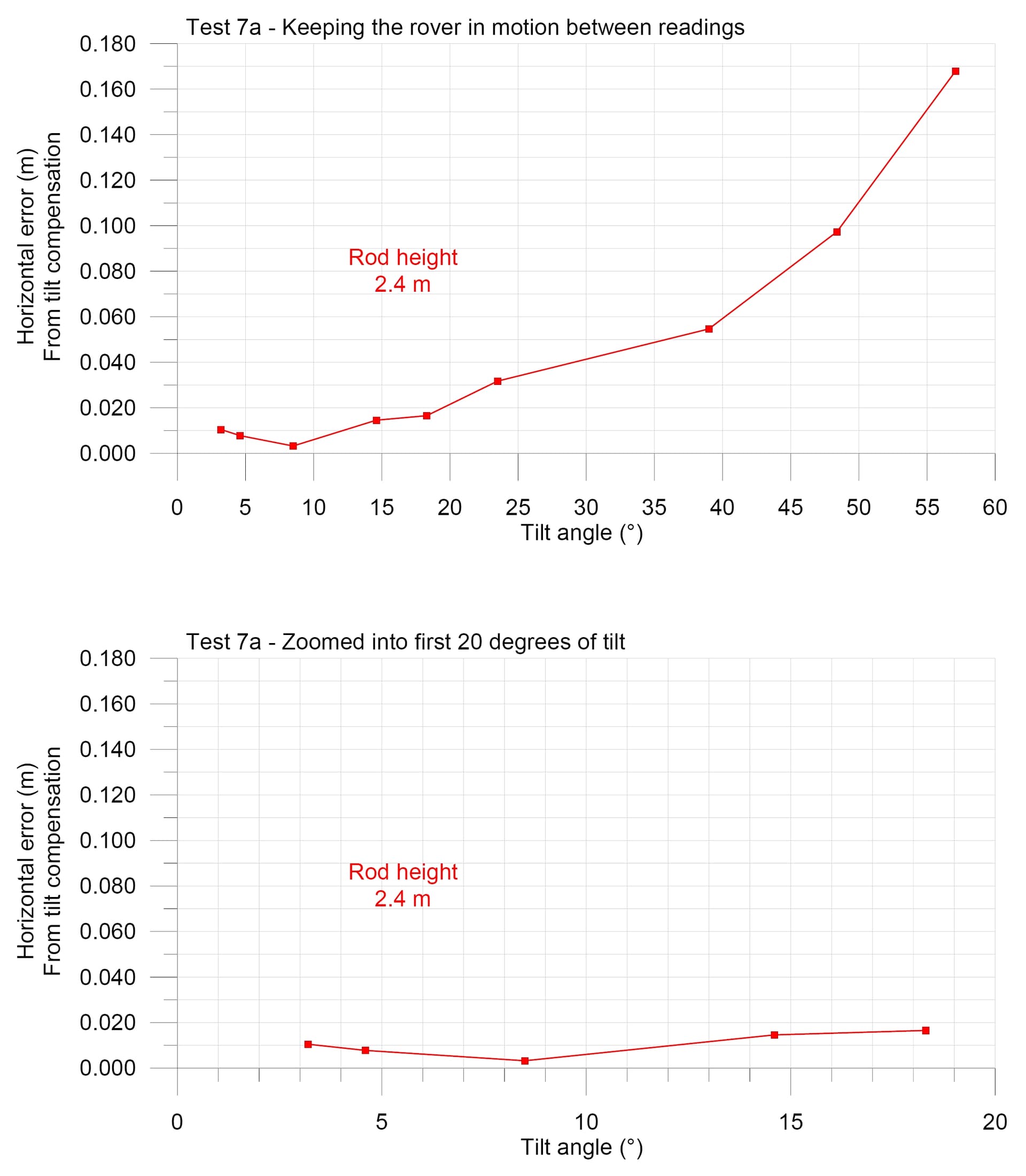
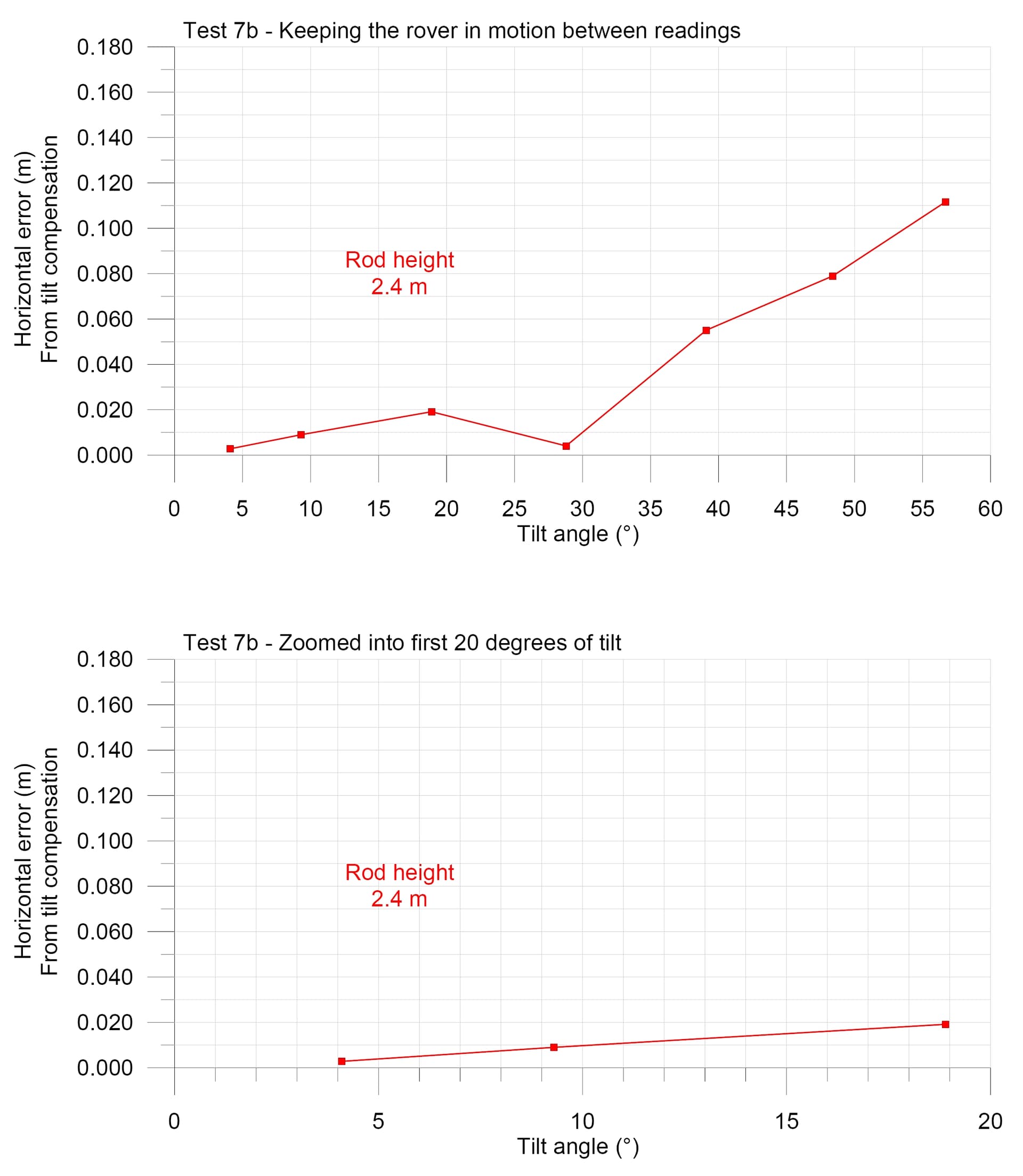
For the tilt tests this time (Tests 7a and 7b) I tried what igor.vereninov suggested (and what mark1st.john is suggesting), to keep the rover more in motion between readings (rather than having rover rod fixed in place on the tripod). I did get better results using that approach. For both results, the horizontal errors stayed below 2 cm for the first 20 degrees of tilt. However, the errors went up relatively sharply at tilt angles greater than 35°. For Test 7a, the errors formed an exponential profile [dXY = 0.0052e^0.0611(TiltDegrees)] hitting 0.168 m at 57°.
So keeping the rover in motion between readings produced horizontal errors staying below 20 mm for tilt angles up to 20 or 30°, but definitely not to 60° as has been stated in the RS3 documentation.
I will try some more tilt tests tomorrow with keeping the rover in motion between readings. I am assuming you are supposed to hold the rover still while taking a reading. Wondering if I might be wrong on that assumption.
Note timd1971 and EBE111057, I am also using a digital angle gauge that reads to a tenth of a degree and matches well with the tilt angles I see on the IMU status (once I’ve zeroed it to the zero reading on the IMU).
I can appreciate that having the rover rod fixed when tilted is probably an important error source in my earlier tests. But if the IMU status is saying “Tilt compensation is ready” then how can anyone know when to believe that status and when not to? I can appreciate that the tripod tests were producing kind of an edge effect like Igor said, but still I think any edge effects like this should be ironed out.
Handheld-still has been my go-to. You don’t need to have active motion during measurement, but it does work (with a slightly higher error).
By the way, you’ll find the “issue” in image stabilization in optics (binoculars, telelenses etc). If you hard-mount something, disable the stabilization.
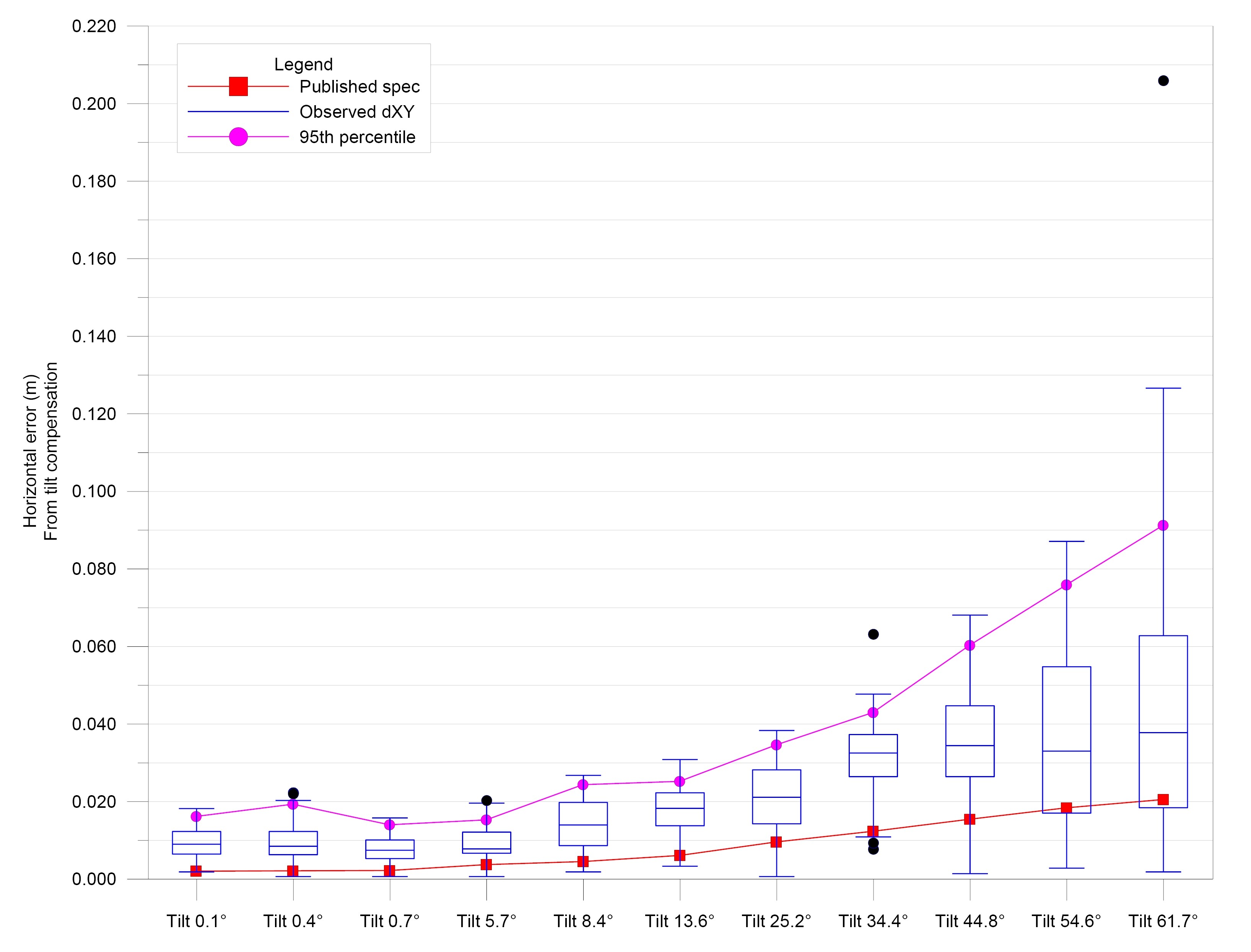
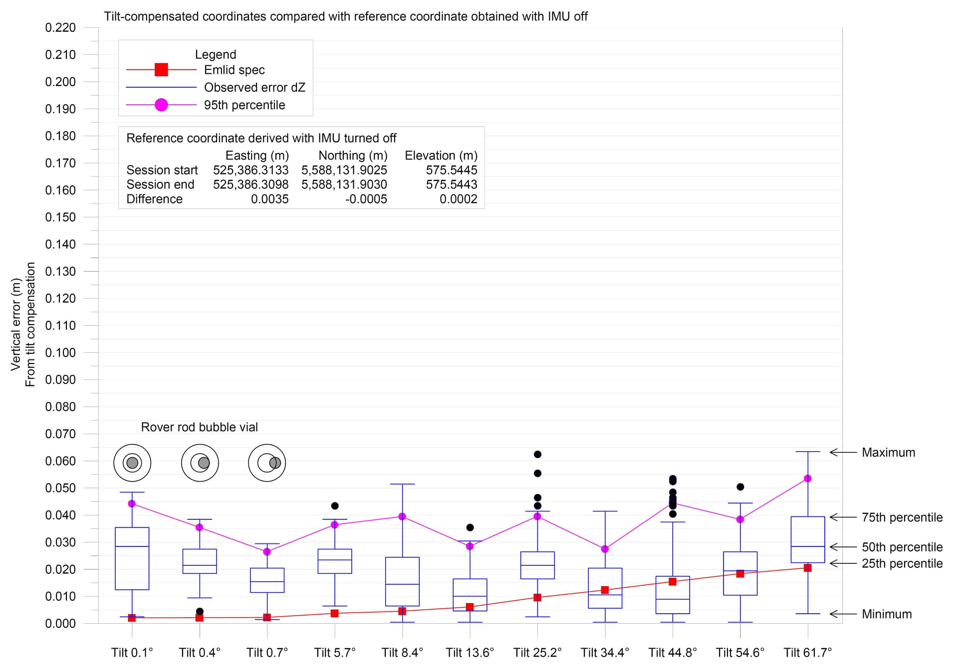
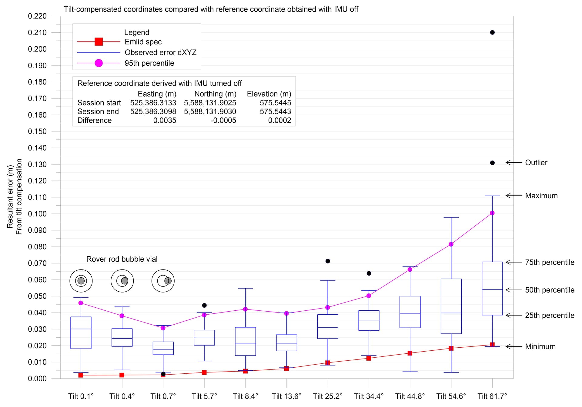
I conducted a test today where I kept the rover rod in motion except during readings. For each reading, a 2-second sampling window was used. Eleven tilt angles were tested ranging from 0.1 to 61.7°. For each tilt angle tested, 100 readings were taken in order to get a statistical distribution of results. Horizontal errors are summarized in the box and whisker plot below.
You shouldn’t be using the 95th percentile, but CEP (50th percentile), which is what the Ublox F9P and most other GNSS receiver give their specs at.
Comparing to a Published specs is like comparing apples and bananas in my opinion. You need to compare to a proper leveled rod, with no tilt compensation enabled. You are comparing precision, not accuracy.
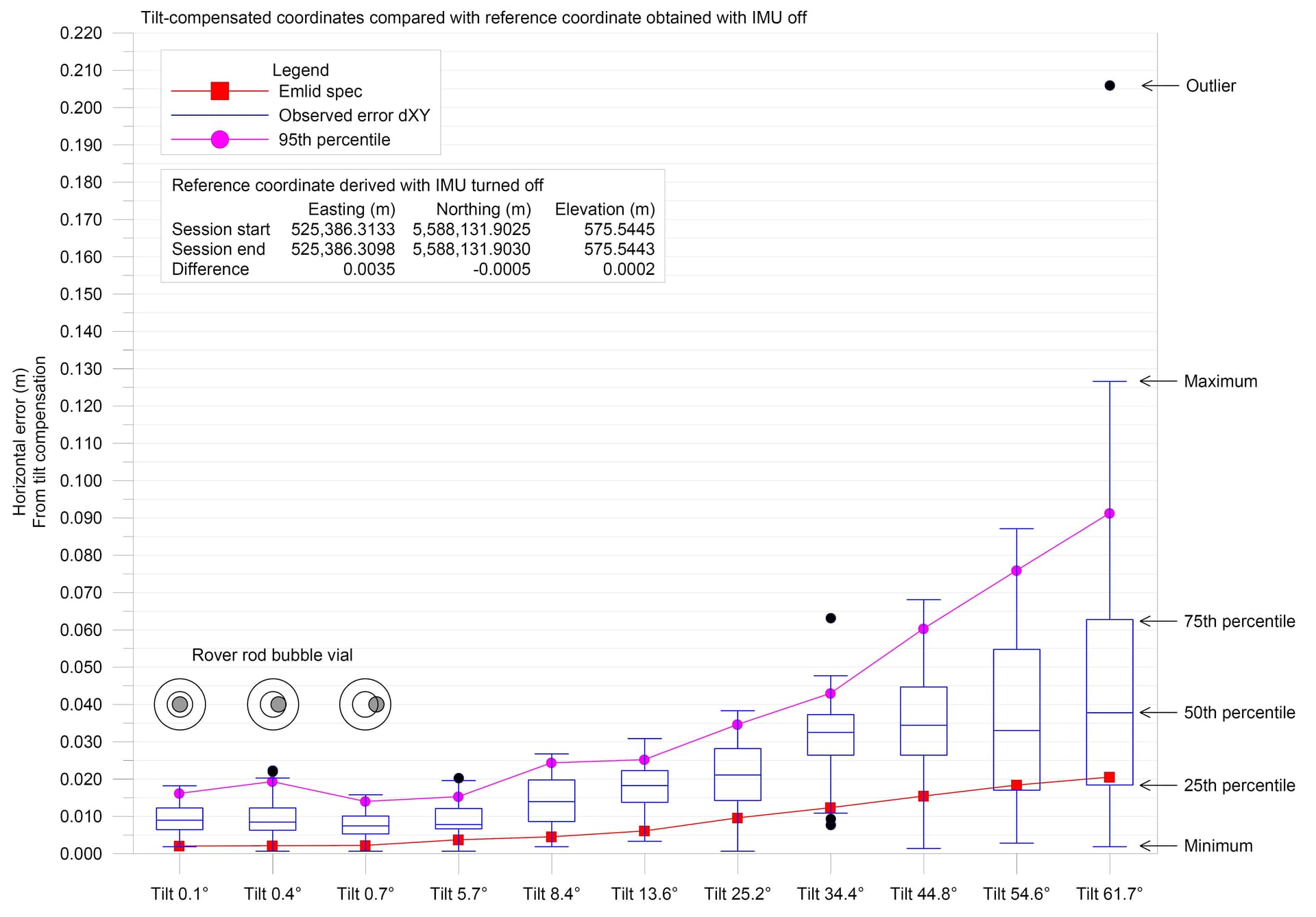
The tilt compensated rover coordinates were compared against the mean reference coordinate obtained from careful measurement made with IMU turned off. The measurements with IMU turned off were made at the start of the session and at the end, with the coordinates at the start and end differing by only 3.5 mm horizontal and 0.2 mm vertical.
Where I state “published spec”, what I mean is the spec that Emlid is advertising for the RS3 in their marketing material and in their official datasheet for the RS3.
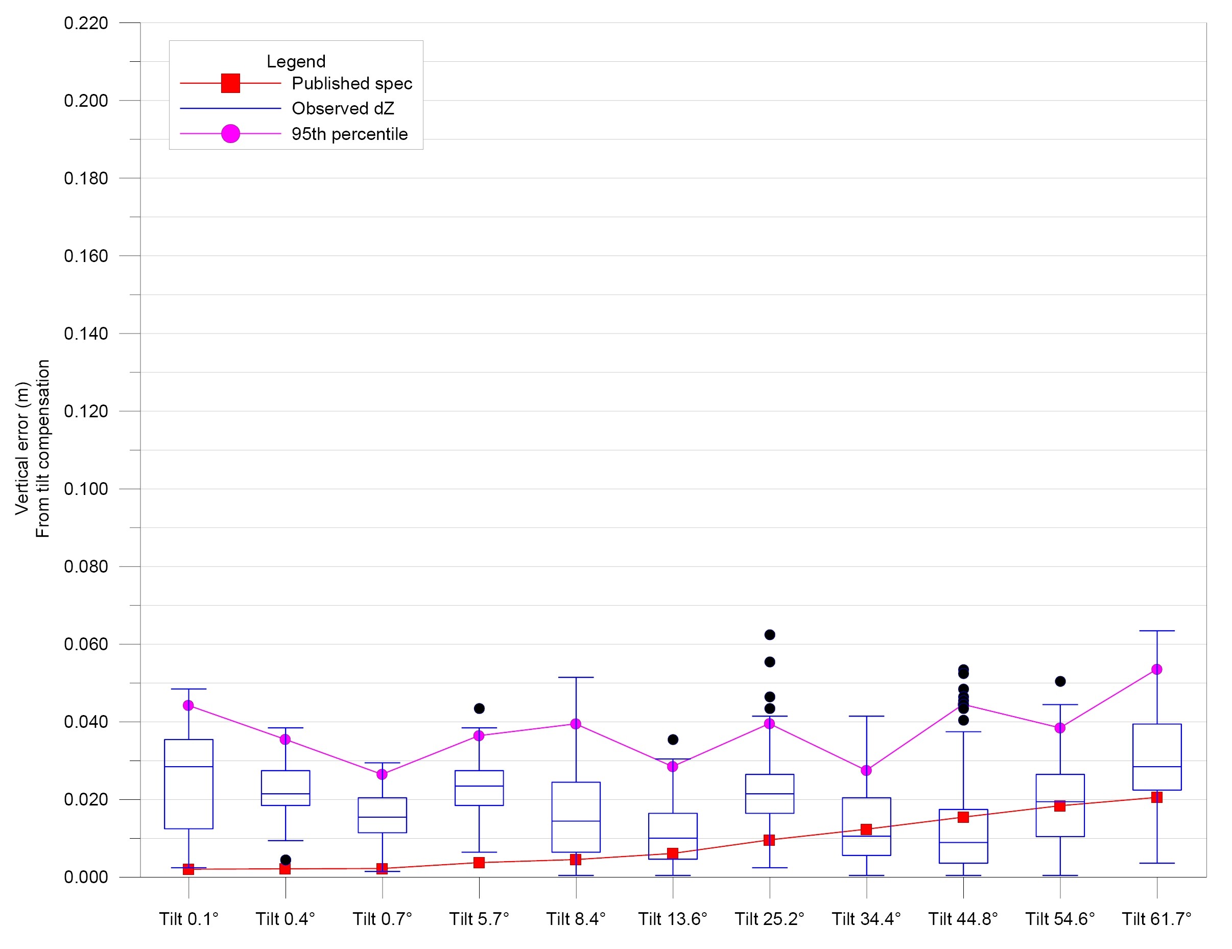
The 50th percentile is shown on the box and whisker plots as the blue horizontal line inside each box. I have updated the box and whisker plots to make the results more clear. I have also included a box plot for the resultant error (dXYZ).