Well, I am not sure the problem is from the FPV, when I did some test in the morning with the the UAV powered on “not the motors” with RC and FPV, the satvis on the rover OBS file is quite good and getting worse when flying.
So instead of removing it, I could only unplug it. If I can limit the work on my nimbus I would be happy
And FPV with OSD is a great backup when flying BVR, I love it, but I will do the test by unplug-in it.
I can see that now, it’s very demanding, on the ground with the drone powered on “not the motors” the SNR was between 20 to 47 dBHz mostly between 30 to 45 dBHz and with just the nose it was mostly between 35 to 47 dBHz. so I guess those value should be good enough if I can get that when flying.
If I get a great SNR while flying after the mast and having the time mark disconnected, I will try again, this time with the time mark connected, if it’s the possible solution, I will do it
I just need a simple checklist to follow on what’s to improve. what is the priority, Should I work on:
Getting rid of a maximum of cycle slips on the satvis, if so, what is acceptable?
Trying to push some SNR lines at or over 35 dBHz, if so, what kind of SNR line I should not see?
About the antenna cable. Is it shield or should I do it and if so can I use copper tape, I don’t have access to much else.
If after all that the connection between the camera and the reach is the problem, will I be able to find it by just powering an arduino with a small battery and simulate a flash trigger and if so, how should I do it, the electronic montage I mean?
If I can get answer to that, I will be happy, because I will see progressively my setup getting better.
PS : I am sorry if I sound a bit cold, normally I am lot more cheerful, but after 2 month I am just tired
I think there is noise introduced via the hot shoe because it is connected to the ground of the whole plane. If you use an arduino with an optocoupler you will solve the problem. The arduino can be powered by the drone. Only the Reach module needs to be isolated.
Isolating the Reach module means that you power it via the power tank, don’t connect it to the flight controller (if that is necessary you need a special isolation there too) and isolate the time mark pin via the octocoupler which is driven by the arduino.
I think that will solve your problem or improve it significantly. And the price will be only 0.25$ and 5 min soldering since you already have the arduino.
Tobias, I understand what you mean, and I think that could be great mod to remove that problem. I just would like to try first with an arduino powered by the same powerbank powering the reach and simulate flash trigger, I’ve got all the hardware at the office.
I just need to know how to set this up
If it’s working, the cause is like you said the shared ground of the aircraft and all it’s accessories, then I will apply your solution.
Edit : By the way, to make it simple in case I can confirm that the shared ground connection is the problem, why not using a simple relay between the flight controller and the Map-02 and powering the camera and the reach with a simple 2S 18650 battery, or up to 2s li-ion the powerbank via upper
I think that is a good approach. The only downside is that you will have to take care that you don’t fry the Reach module by connecting it directly to die Arduino. You habe to read wheter the pin supports 5v. I actually think it is not.
The camera might be the source of the noise, or did you test that? I prefere the octocoupler solution because you need less power to drive it. If you have some Arduino relays laying around you might have an optocoupler which you could desolder there too.
I am at a drone expo in Abidjan and they have the same setup, the same equipment and the same connection than me. But they are using a 15cm pole with a spiral antenna. It work perfectly for them
Did they tell you they had the same problem? Of course you can spend 200$ that fixes the problem. Lucky for you if you do not bother to test the 0.24$ solution before that.
For fun I created a small poll/bet what the users think will most likely solve the problem:
Don’t worry, I will first try to take pictures again with the standard antenna on the pole plus 10cm ground plate on it. That’s a 10min job. If it’s still bad, then i will power the camera with an external battery and trigger it via arduino, I already done it, i know how to do it, also a 10min job.
But also a great way for me to progress would be to know the answer about the following points:
Some answers based on my experience, not specific knowledge.
Cycle slips are bad, they should only occure at the beginning and end of the satellite visibility (shortly after and before they come above or go below the horizon).
I think during the flight at least 6 satellites should be above 45 dBHz. Almost all the rest should be above 35 dBHz.
The cable should be already very well shielded. Its a coax cable.
I have a very noisy 3DR 433MHz radio from Drotek. If I connected that to my Reach modules (even tx/rx only and not the power but with common ground) the reception got very bad and the bars where jumping around. If I do not connect them but only have them running next to the modules there is almost no impact.
You may get a better signal quality by moving your antenna to a pole but the main problem is the noise in your system and only replacement will or isolation may help.
You also should consider that the camera is the source of the noise.
I will try what I said in the previous post, even switch camera and camera all in one cable and before receiving the spiral antenna, I will try your solution
Ok, I was able to do a few tests today, and the last one was disconnecting the FPV transmitter and unplugging the camera from the reach. The antenna is mounted 15cm above the fuselage under an aluminium ground plate. Like before the reach is powered by an external source and not the UAV battery.
It was a simple takeoff in multirotor mode, 15m above the ground and clear of obstacle, the logs are pretty bad, lots of cycle slips and SNR is between 28 to 40 dBHz.
So since the result is bad even without connecting the camera, no point in trying to isolate its ground.
So what can I still do? a 1m mast? a 30mm aluminium ground plate? A spiral antenna?
If other Nimbus the exact same setup “once the FPV is disconnected” are working perfectly with the Reach why not mine?
And on all the Nimbus with Reach, I could see this model or similar:
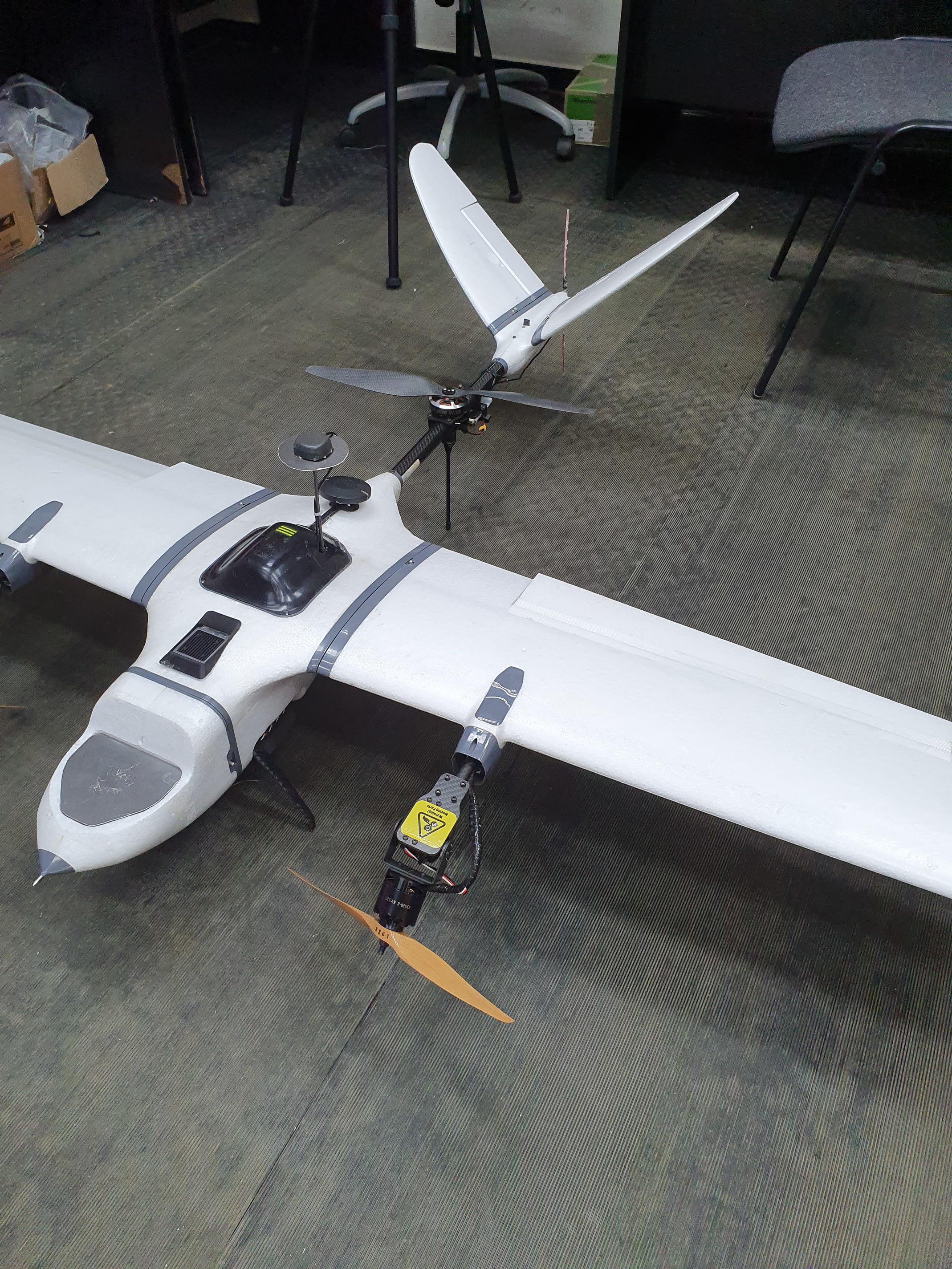
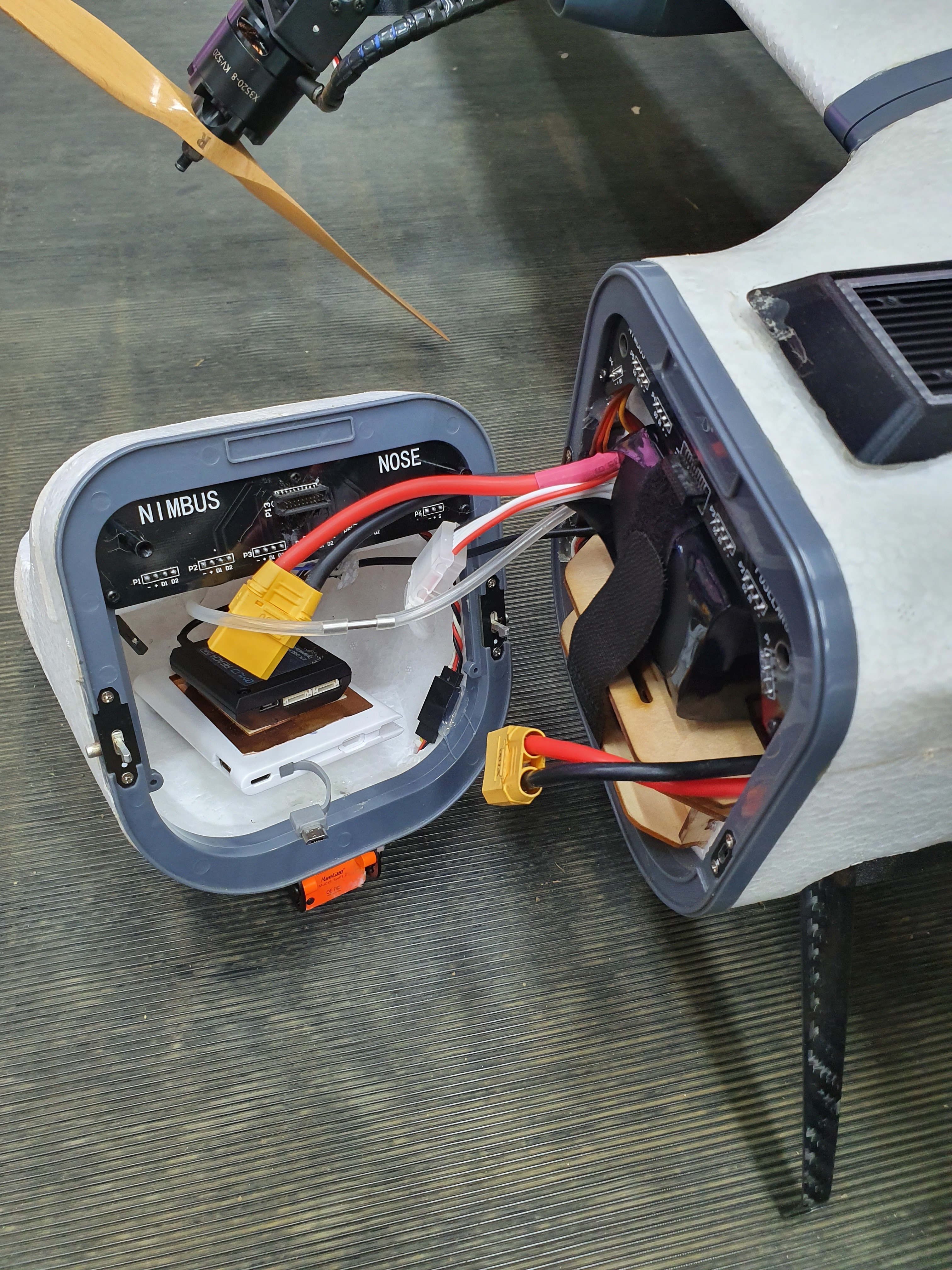
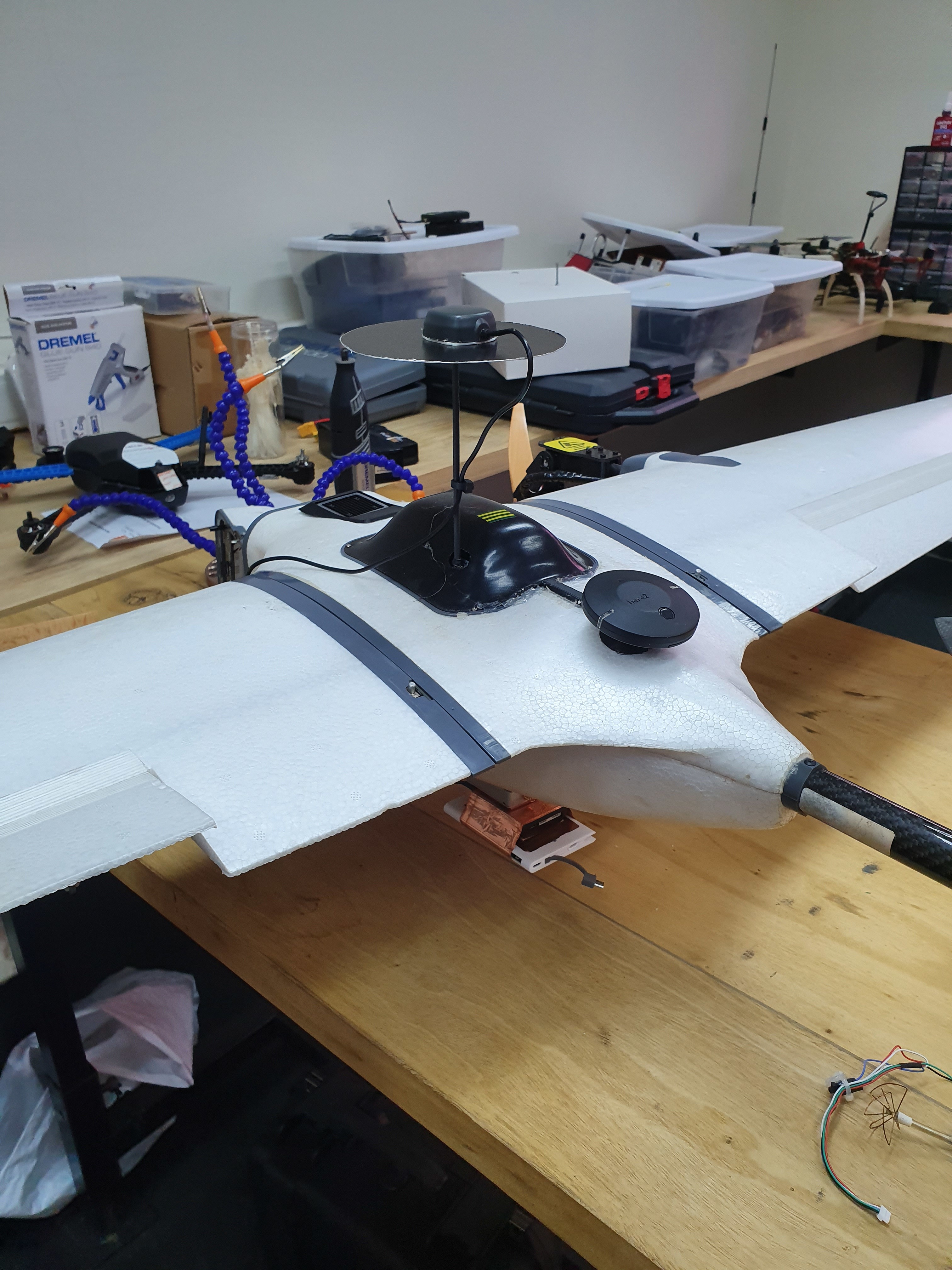
Could you please post some pictures of the setup? Where is the unit? Is it still next to that BEC? Ist the module no longer connected to anything but the usb battery?
You should also make a list (here) of tests you have done to narrow down the source of errors.
I installed the powerbank inside the nose, it’s a bit close to the battery cable, but that is the only inside place I have if I install it outside it will generate drag and won’t like drops of rain.
It’s quite small actually, the only place large enough is inside the nose, the rest is packed up
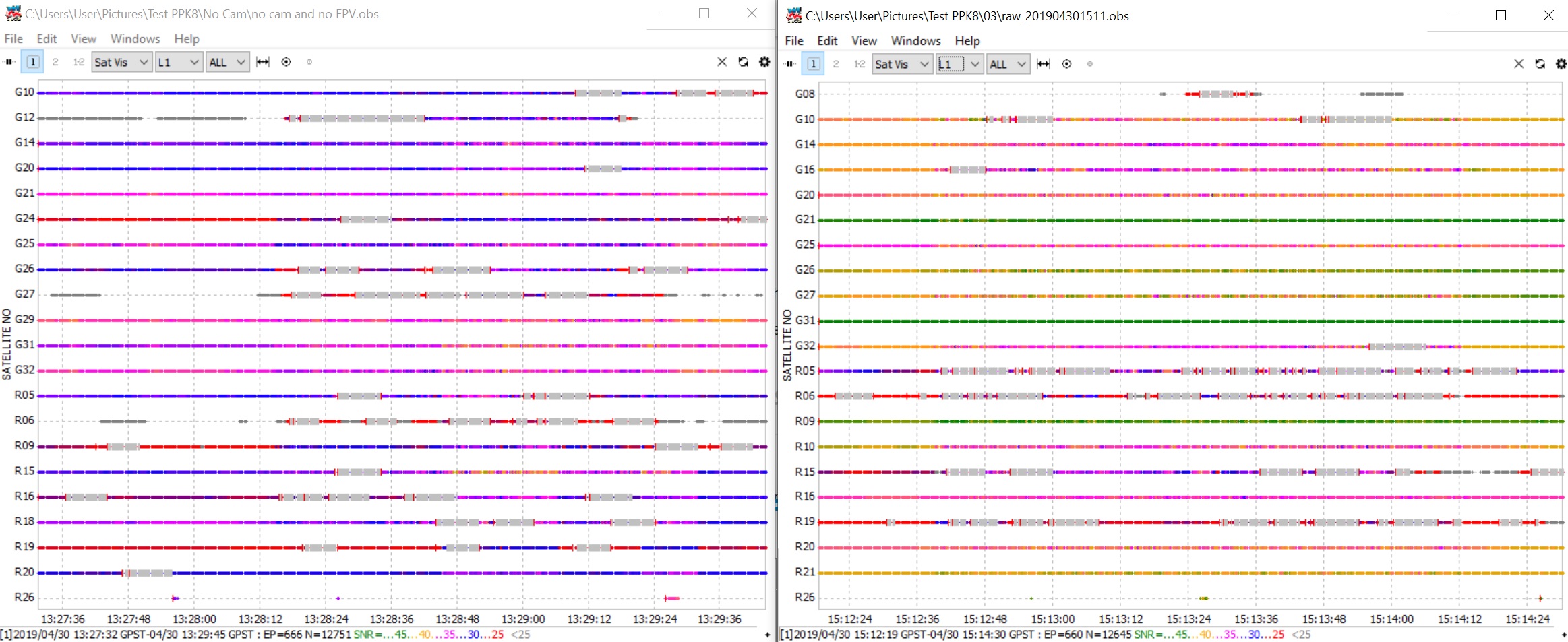
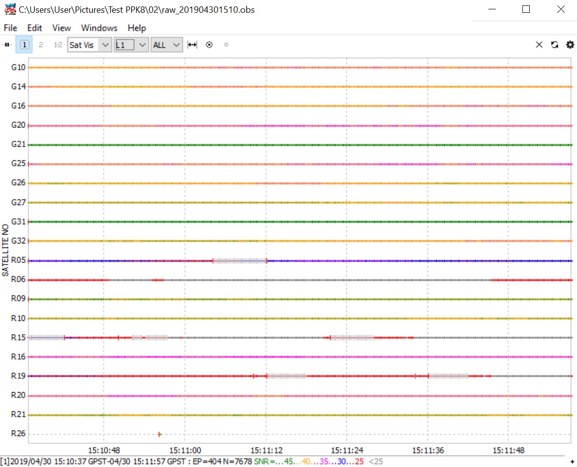
So after doing the test with the Reach under the belly, things are getting better, you can see it on the image bellow, left “the Reach in the nose” and right “the Reach under the belly”
I could wrap it up in copper tape, but I will need to leave holes for USB and antenna connection. I also bought some more aluminium sheet, I cut a 12cm diameter ground plate.
If I can power it via the red BEC then I should be able to put the reach on the right of the mast. So I should try powering it internally first, see if there is any interference.