We are looking at a new build that will have a multiple camera payload. I note that the Reach M+ has two event mark input pins, can you advise how the events marks from the different cameras are dealt with in the post-processing workflow.
Likewise the Ublox M8T has 2 external interrupt pins. I believe the hardware is capable, my question is more on datalogging and post processing side. Unfortunately I only have older Reach units available so I am unable to test this myself.
A UBX-TIM-TM2 message is output at the next epoch if
• the UBX-TIM-TM2 message is enabled
• a rising or falling edge was triggered since last epoch on one of the EXTINT channels
The UBX-TIM-TM2 messages include time of the last timemark, new rising/falling edge indicator, time source, validity, number of marks and a quantization error. The timemark is triggered continuously.
The UBX-TIM-TM2 message includes the channel on which the timemark was recorded.
So:
you can record on both channels
you can differentiate to which channel the timemark belongs (you might need a script to divide the result, take a look at the timemark time machine, it would be possible to add a function to split the RINEX file in two files for each channel)
you only can record one event per epoche, so you need to make sure that you fire the events in an alternating pattern. I.e. release the second camera with a 500ms delay or better release the the second camera after you have recorded the event of the first camera - e.g. with an additional Arduino or ask Ardupilot to integrate such a function.
I’m interested in such setup, I think it would be quite easy to integrate with an additional microcontroller (Arduino) which handles the triggering. It would basically need to have an input to trigger the release sequence, then release the first camera, wait for the hot shoe signal, release the second camera after a certain delay and wait for the second hot shoe signal before allowing the first camera to be released again (also with an delay). I guess that is some lines of code, some optocoplers and there you go for less than 15€ even if you go for a Adafruit build microcontroller.
But as @Stu74 I have 3 of the original units without the second input, so I cannot test it. Anyhow, with the time offset you could also use the original Reach unit if you use a pattern like “first camera, 250 ms delay, second camera, 1.000 ms delay”. The timemark time machine could then sort out each timemark where the previous timemark was less than 300 ms to ago to another RINEX file.
I also don’t think a delay introduces an additional problem if you want to overlay different channels. The problem that you do not have exactly matching pixels for each channel is introduced by using different cameras anyhow and you need to fix that somehow else.
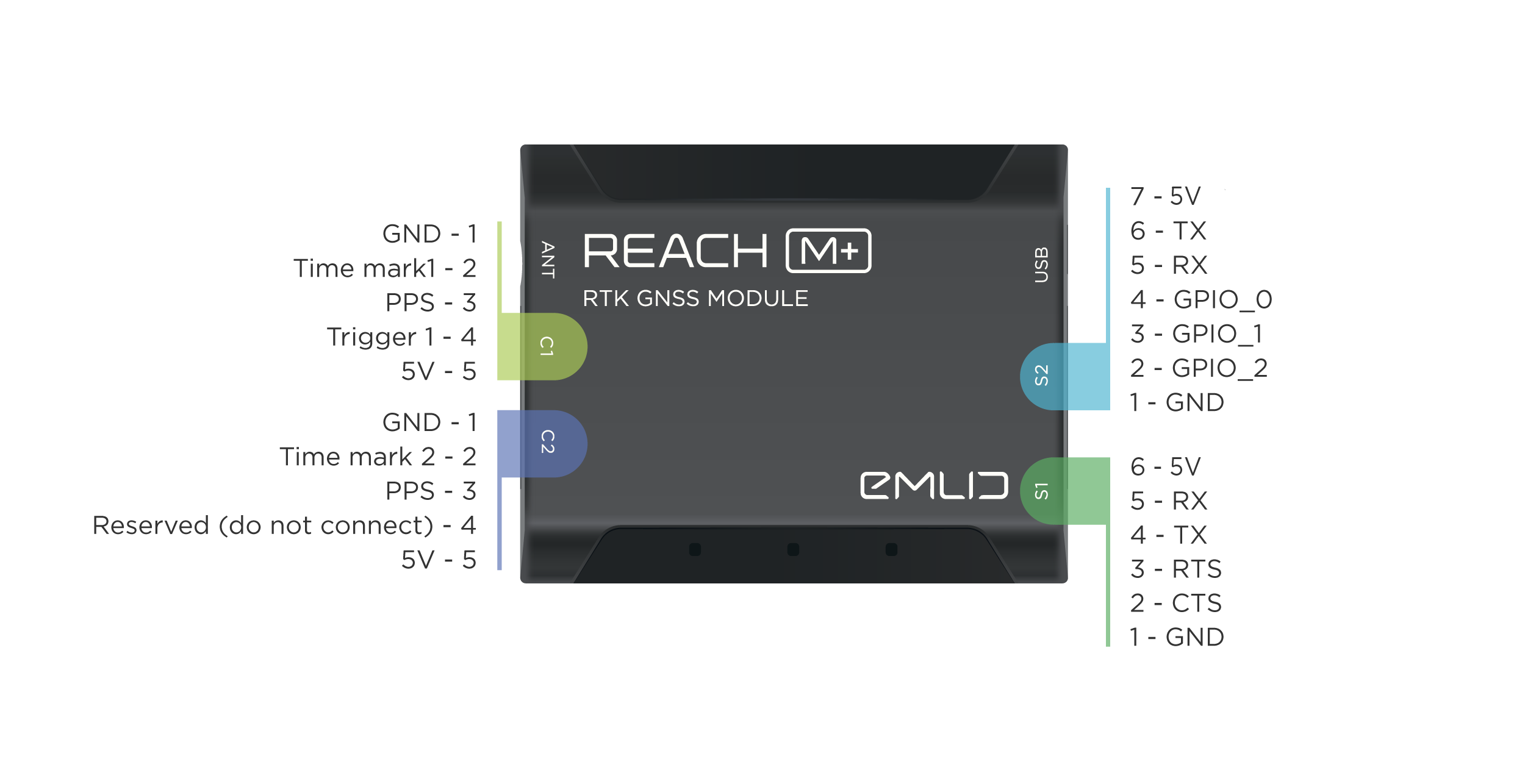
Reach provides 2 Time mark pins, and each of them can be used for time mark recording.
However, in the meantime, ReachView doesn’t support dividing time marks from these pins, so if you use 2 cameras simultaneously, events from these cameras will be mixed up.
I think you can try the workaround suggested by @tobias-dahms to implement it.
I don’t think it is possible or important since the main limitation is given by the fact that the receiver does only report the last event per epoch. The worst thing that can happen is that you loose the accuracy because you “overwrite” the first event by the second. So you will need to do some release timing anyhow. You need to record the events of each camera in different epochs. With a 5Hz update rate you need to introduce an delay of 250 ms to be shure that the second event is recorded in the next epoche even if the previous event was recorded in the first ms of the previous epoche.
The only solution to avoid that is to use a second Reach unit - one for each camera. If you use the method I proposed you can save 310 $ and 110g without any additional drawbacks.
Thanks all for your detailed input. We will likely solve this with 2 reach units as this will be for a large fixed wing aircraft and tolerant to the weight penalty . Synchronizing the cameras is a requirement for this application. Hopefully Ublox overcome this limitation with new hardware. FYI the Novatel EOM7 boards are the only ones that support multiple event marks (4), obviously at a vastly different price point to Reach… Other dual frequency boards from Trimble, Swiftnav, Septentrio & Tersus only feature a single event mark.
Ok, I guess that is the more straightforward solution.
For what will you use your dual camera setup?
I still wonder about the synchronisation. I know from my colleague who is working with a Sequoia that even with this multi camera you will have to have an algorithm to correct the offset between the single cameras. And for photogrammetry even the rolling shutter has an impact.
I would be very interested to know if you need and how you overcome that problem. I guess that will help alot when I finally find the time to build my two camera plane.
At this stage the payload will be a pair of mirrorless dslr cameras, one standard RGB & the other modified to NirRG spectrum. Initially the cameras will be treated as independent in a combined alignment/BBA and then split out for the required surface modelling or imagery products. However small variations could be expected due to the camera offset (position and angular) and variable delays in the camera shutter release.
We would only be using cameras with global shutters in this application.
It is possible down the line to rectify the NirRG camera to the RGB camera together. Lens distortion can be corrected for both cameras and the imagery can be rectified to a common perspective transformation, effective a zero distortion pseudo frame. This method is used by large format frame survey cameras, such as the Ultracam and DMC. These cameras typically have ~ 4 panchromatic cameras that are rectified and stitched into a large pseudo frame. 4 lower resolution multi-spectral cameras are then rectified and pan-sharpened using the pan frame. The user ends up with a zero distortion, 4 channel high resolution perspective image, that is ready for the photogrammetric workflow. I have preformed this perspective transformation rectification successfully using OpenCV using some terrestrial test imagery.
Going back a little bit know, but as camera parameters (using photoscan camera calibration tool) were known I used undistort to apply them. Then I adopted this method from the fantastic Pyimagesearch… This uses sift features, descriptor matching, finds homography & applies the perspective transform warping…
Best results for filters have been from maxmax, our camera has been modified with one of their filters but I think they are also available as an external filter. They are not cheap… We use the GRNir version