good info, thanks.
is this experience info? Are you checked it in your projects?
My info is experienced and checked. I write only checked on my projects info.
good info, thanks.
is this experience info? Are you checked it in your projects?
My info is experienced and checked. I write only checked on my projects info.
If you shot a lot of photos front overlap, you could make their filter in the Teobox software.
Always 
PPK with GCP’s are our standard operating procedure now. Too easy not to. All mapping missions run through the same process including DTM filtering and integration for GPS machine control project files.
If we use front overlap 75% and sidelap 55% we get about 12 photos on each point. But our experience says us that is better to use 85% front overlap. That excludes presents of blind zones.
At what altitude are you getting 12 with 55%?
The overlap doesn’t depend on altitude. The altitude influences only on scale.
You will get 12 points at any height with an overlap of 55/75%
55% overlap is only going to supply two columns (three VERY rarely) and 75% is going to supply 4 rows. That is 8 reliable images per pixel.
75/65 will give you 12.
and it does not depend on height.
It should not, but it does. The increased amount of area captured does give each tie-point a better chance to be seen when it is right on the edge of the frame. Unfortunately running such low overlaps quite often puts the subject far out on the frame. It becomes distorted and blurred. Running higher overlaps gives you more chances of closer proximity captures with better focus. The computer vision algorithms do pay attention to this and for instance quite often ignore GCP’s that are on the outer edges of the frame.
Do you have examples of maps that were used to make a detailed terrain model. Not a surface model. Everything that you have shared thus far has been of surveys that you could barely see the ground so I am not sure what you are considering accurate if all you can see are slight spots and your checkpoints?
Soon i will write manual about settings of the flight with Teodrone.
Manual will be based on my experience.
I will show the link on it here…
That would be amazing!
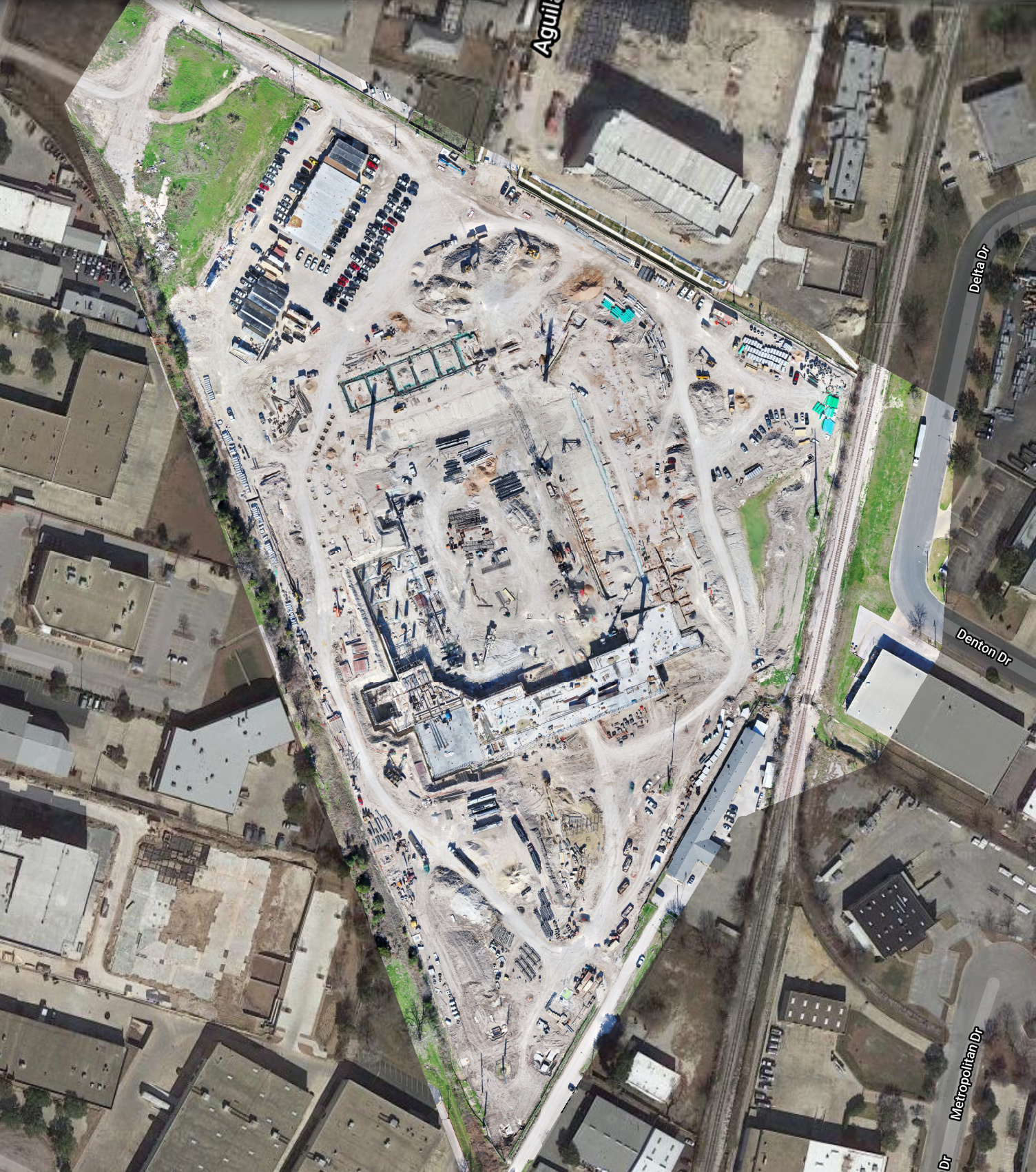
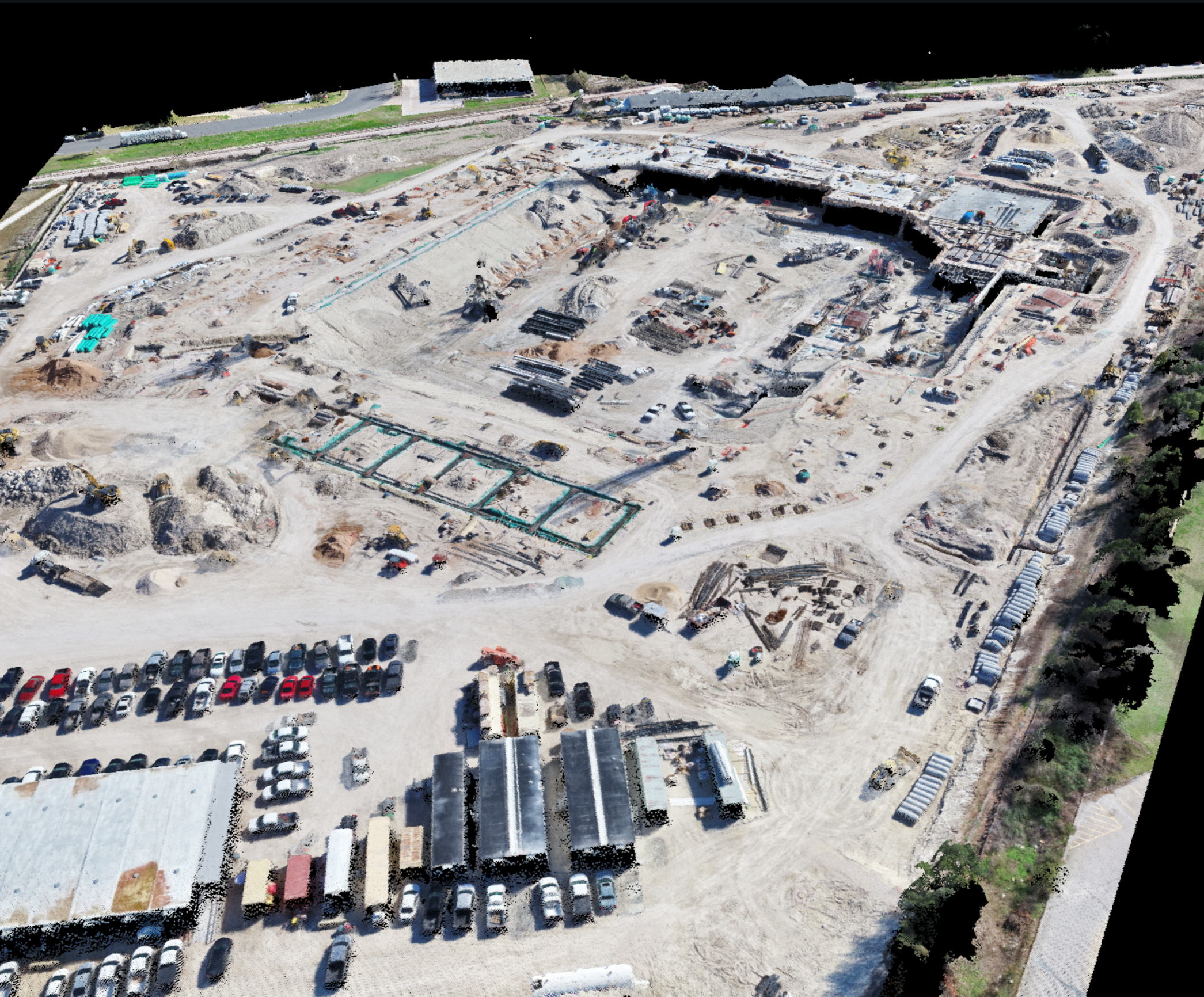
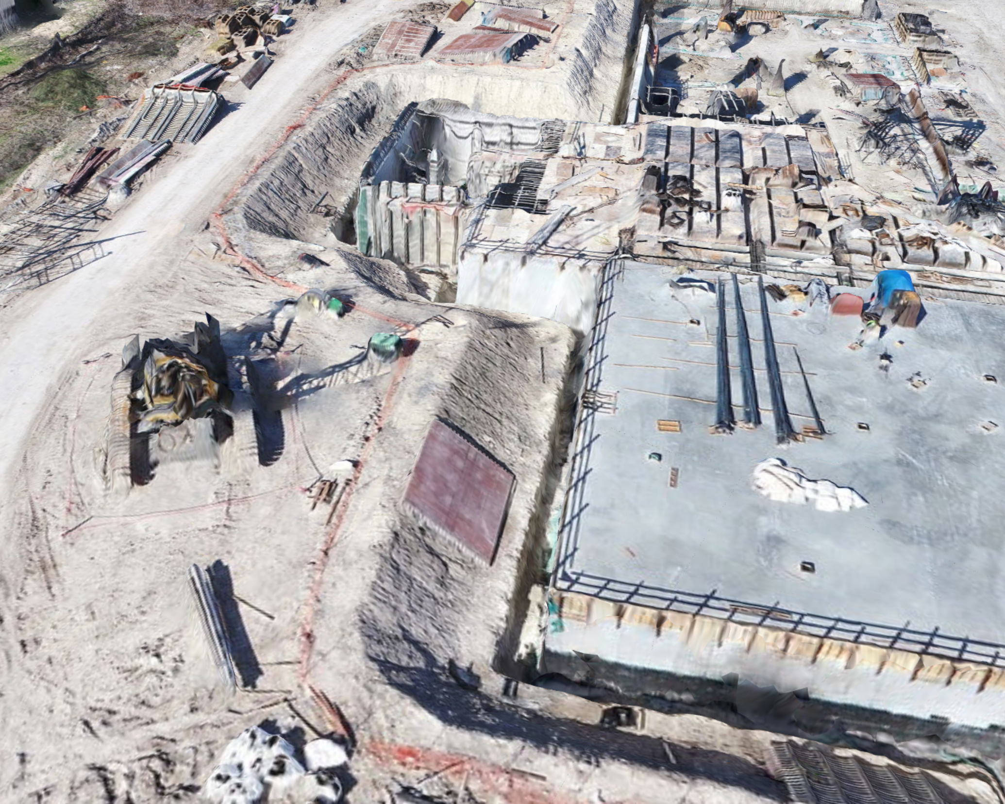
Something more like this? This is where I think what we map is very different and requires different methods. There are allot of straight vertical edges and spaces in between that getting enough overlap is mandatory to acquire. By the time I am done with the DTM there will be no cars, stockpile or pieces of equipment. I am actually doing a wall backfill estimate to show overburden material in the trench around the building. This one was processed in our terrain mode so the vertical faces won’t be as precise as the structure mode model that is still processing.
You’re wrong.
For aerial photography, 40*60 is enough.
60% overlap between images within the route.(front overlap)
40% overlap between routes.(side overlap)
This overlap is “from the textbook”.
With this overlap, the angle between the projected beams is maximum, which is better for accuracy.
But with this overlap, you can only fly in open areas without forests and buildings (or if there are few of them).
When you need to take aerial photos over a forest or densely built-up area, you need to increase the overlap. 60*80 is enough .
A large overlap (80-95%) makes a sharp angle between the beams and this is bad for accuracy.
Getting a beautiful 3D model is not an indicator of accuracy.
in this project, the overlap was minimal and sufficient.
Do you mean that the accuracy shown on the GCP 5-9cm is only the accuracy on the GCP itself, and between them on other sections it will be different?
This is not true. the accuracy of 5-9 cm will be in any point of this territory, except for those where high dense grass grows.
GCP from the project do not participate in the optimization of the project, and show the real difference between coordinates for aerial photography and RTK.
Here is an example of how it works: Современный подход к вычислению объемов горных и земляных работ
2-3 cm difference between the data for the entire object with a difference of a month.
I wanted to rephrase that because you all obviously believe in what you are doing and it seems to be working for you. I am having a hard time with your information being so much different than what everyone else in the industry says. The project above for example would absolutely not work with the heights and overlaps that you state. Thank you for the good discussions though!
I studied photogrammetry, I taught photogrammetry.
I have been flying UAVs for photogrammetry for 10 years.
I did thousands of plans, hundreds of tests with many professionals (and professors) and types of UAVs (about 20 different types).
our projects range from 100 to 10,000 hectares on average (entire towns and cities, large mining companies).
Do you really think that customers believe us without any verification?
Always surveyors look at our materials, compare them with their own, and make control measurements.
We also can not take materials without instrumental ground measurements. Control sample measurements (houses, roads, paths, power lines) are ALWAYS performed. Always measured and compared with aerial photography data.
At least triple precision control.
p. s. accuracy in open areas, without grass.
when I talk about 5cm accuracy - it’s not on GCP, but in other random places (without grass and forest).
When I say 5 cm, this is the result of careful, experienced work with the plan and preparation.
If you come, fly on automatic settings and automatically calculate everything-then there can be from 20cm to 1 meter.
Thank you for the explanation and I appreciate your professionalism, but if you look back at the origin of this part of the discussion the claim was 2-3cm. Acquiring 5cm is easy.
Hey guys,
do you think that the new multiband reach M2 is a game changer for the UAV mapping?
As a surveyor I never trusted the L1-only fixed solutions. Even the L1-L2 solutions sometimes fail if the conditions are not optimal.
I would like to see the M2 integrated in the Phantom 4 Pro/Adv and check the results.
If anyone has done some testing let me know!