


REACH M+ and DJI MAVIC 2 PRO integration for RTK /PPK precision survey
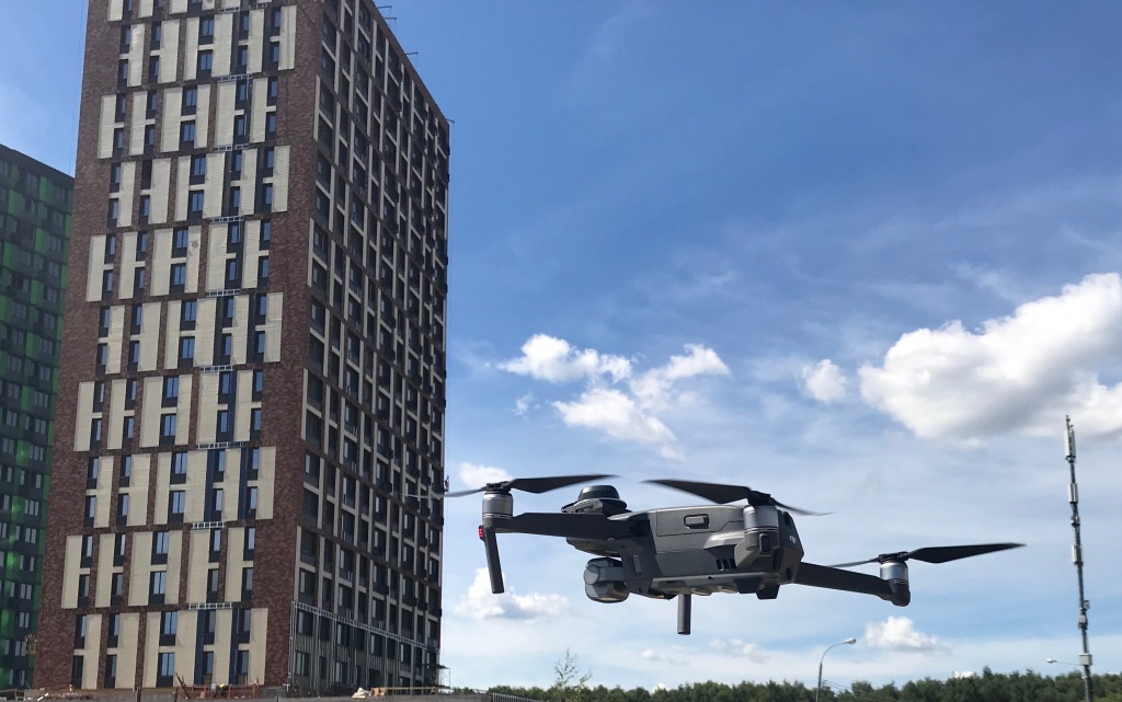
We would like to present the latest development – high precision survey grade drone DJI MAVIC 2 PRO RTK / PPK with EMLID REACH M+ on board.
Light weight survey grade GNSS receiver was installed on DJI MAVIC 2 PRO and connected via advanced Topodrone synchronization system with Hasselblad 20 Mp camera.
With DJI MAVIC 2 PRO PPK you can easily achieve 3-5 cm x,y,z accuracy of orthophoto or 3D model without using ground control points (GCP)
DJI MAVIC 2 PRO PPK has been tested in the most demanding conditions of surveying works, such as urban areas and rugged relief of open pit at an operating mining site.
Below you can find survey projects results over Joensuu city, Finland and open pit in Masbate island.
PROJECT1. AERIAL SURVEY IN FINLAND
In June 2019, International Forestry Natural Resources Institute Finland (Luke) ran some accuracy tests of DJI MAVIC 2 PPK upgraded by Topodrone team.
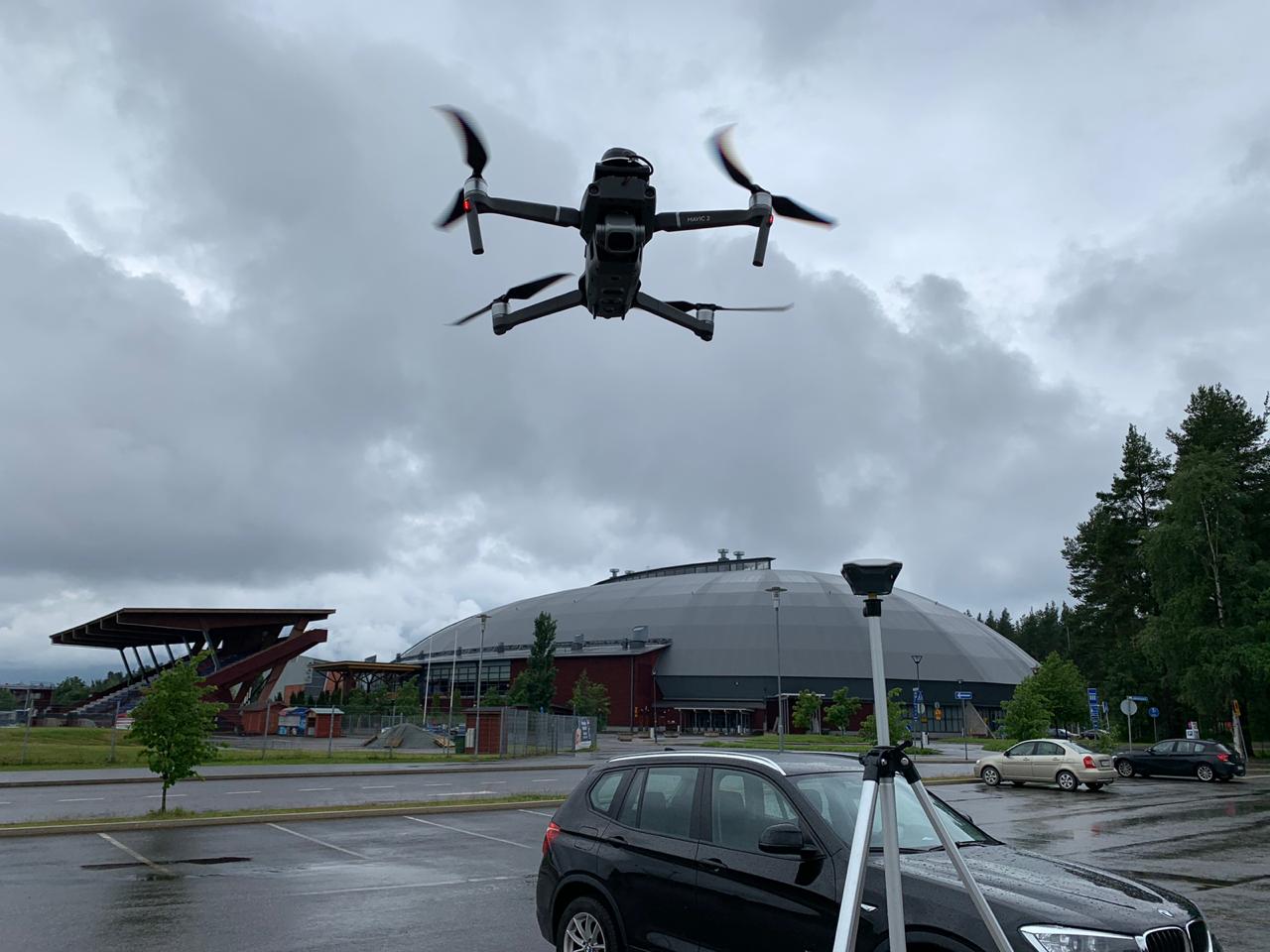
Luke conducted aerial survey in Joensuu city, Finland using DJI MAVIC 2 with additionally installed EMLID Reach M+ GNSS receiver on board and EMLID REACH RS+ as a base station.
The goal was to create a detailed 3D model and an orthomosaic without using ground control points for aerial triangulation and check the accuracy of the model by comparing with already measured check points on the ground.
Before flights 8 ground control points (GCPs) were set at the test site. All GCPs were captured with a Reach RS+ rover. Corrections were acquired from an RS+ base in RTK mode.
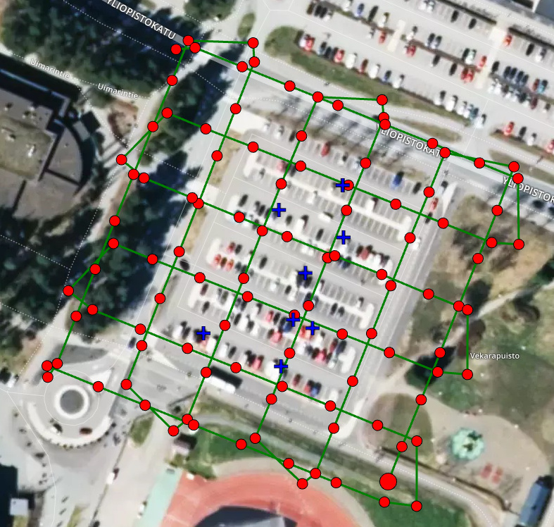
Pic. 1 Area of interest, GCPs location (blue croses)
Then survey mission was prepared in PIX4D capture app, double grid mission with 80 % front and side overlapping at 80 meters altitude was setup. Pic.1
Than aerial survey was performed, whole process took less than twenty minutes, at the same time REACH RS+ base station was collecting raw GNSS data for further processing.
After flight, raw logs from the drone and base station were downloaded and post-processed using the geospatial analysis RTK LIB and TOPOSETTER software. This was done in order to get precise x,y,z position of each photo. Pic.2
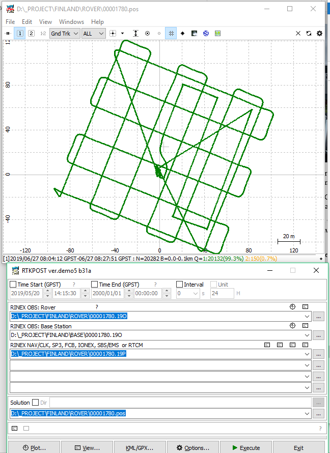
Pic. 2 Processing in RTKLIB
At the next step, institute engineers imported images captured by the drone together with the list of accurate photos coordinates to PIX4D software.
Photogrammetry processing in PIX4D software did not take a lot of time and was made totally in automatic mode, only precise position of images location were used for aerial triangulation.
Once initial processing step of block triangulation was done, eight ground control points were imported to the project to check accuracy. Total RMS error was no more than 3 cm. You can see results against GCPs in Tab.1 Please follow the link to download the full Pix4D report.

Pic. 3 Pix4D data processing
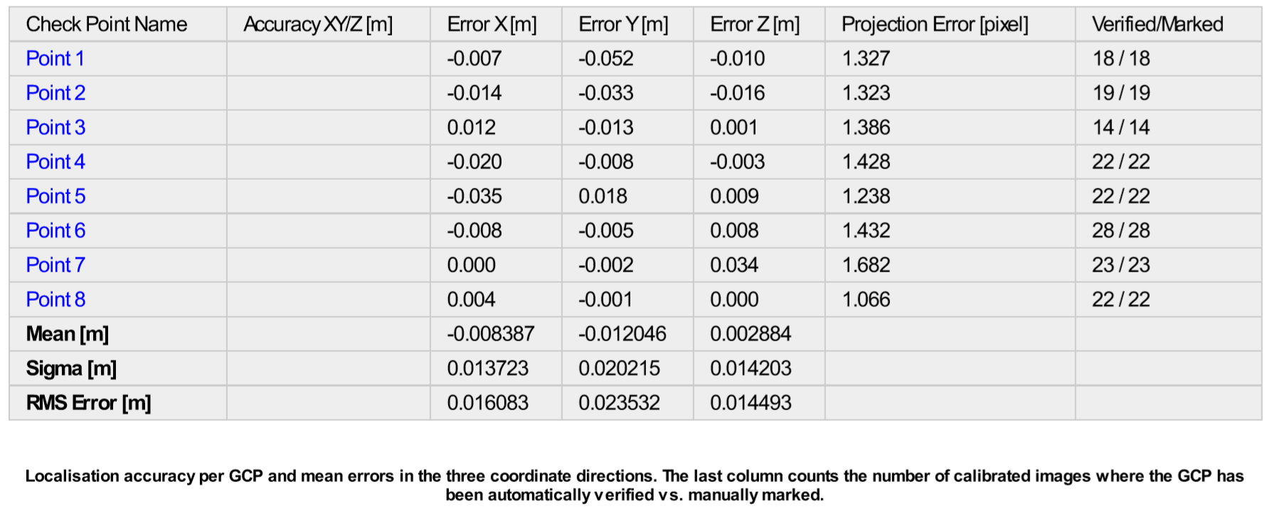
Tab. 1. Pix4D accuracy report
Finally 3D points cloud was generated together with automatic classification.

Pic.4 3D model
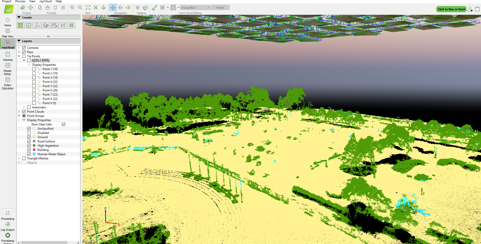
Pic.5 Points cloud classification
“There is a great advantage in using DJI MAVIC 2 PPK upgraded by Topodrone team. Reach M+ connected by Topodrone synchronization system with 20 Mp camera for capturing photo events with centimeter level accuracy converts DJI MAVIC 2 Pro drone to an affordable professional survey tool. It allows us to spend less working hours on field works than on a traditional survey, now we don’t need to lay GCPs and because of optimizing the resources of the team, we can deliver the best quality data to our clients promptly. What I also would like to add about DJI MAVIC 2 PPK is that it’s very easy to configure and use.” — Eugene Lopatin, Senior Researcher, International Forestry Natural Resources Institute Finland (Luke)

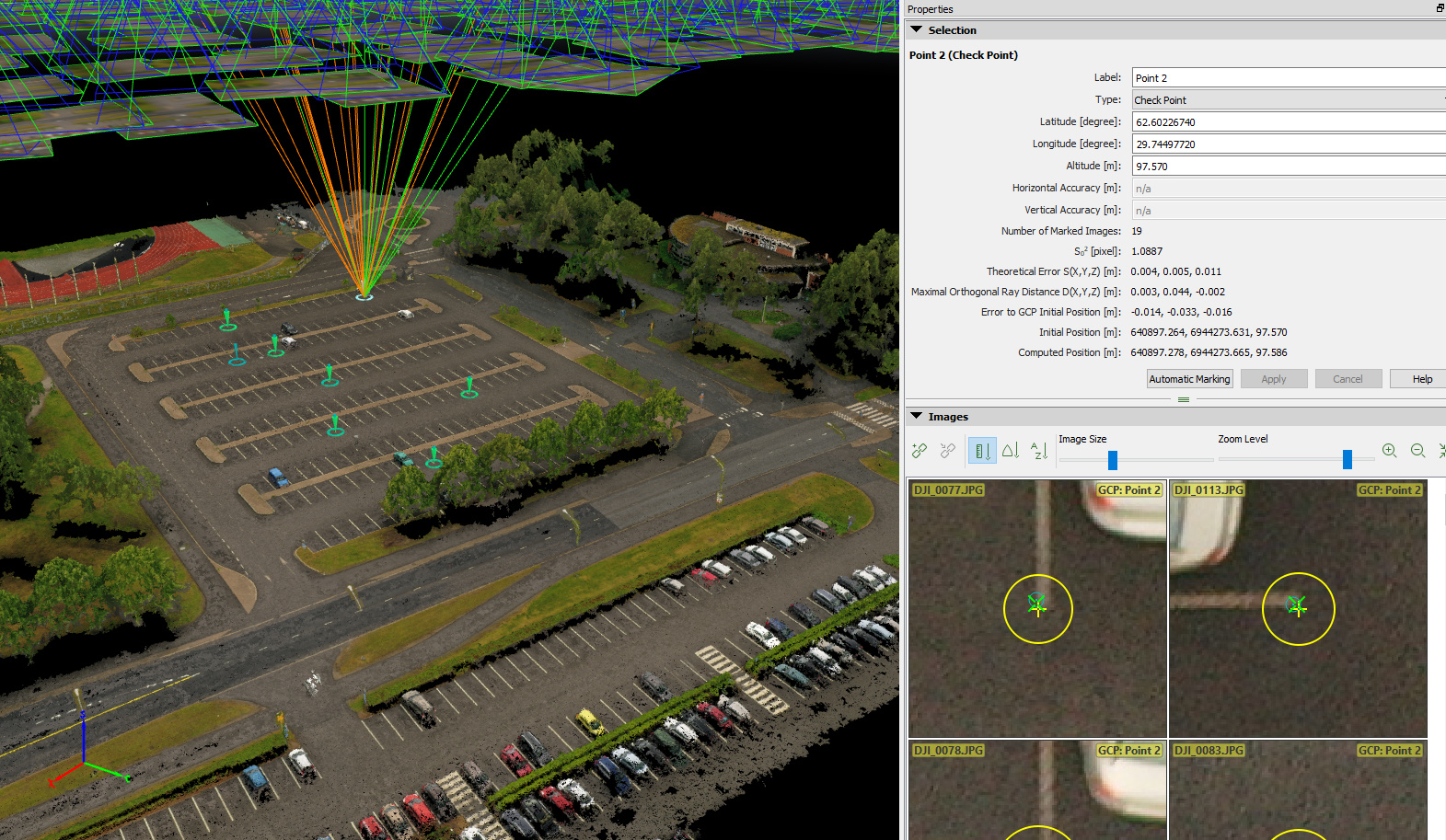

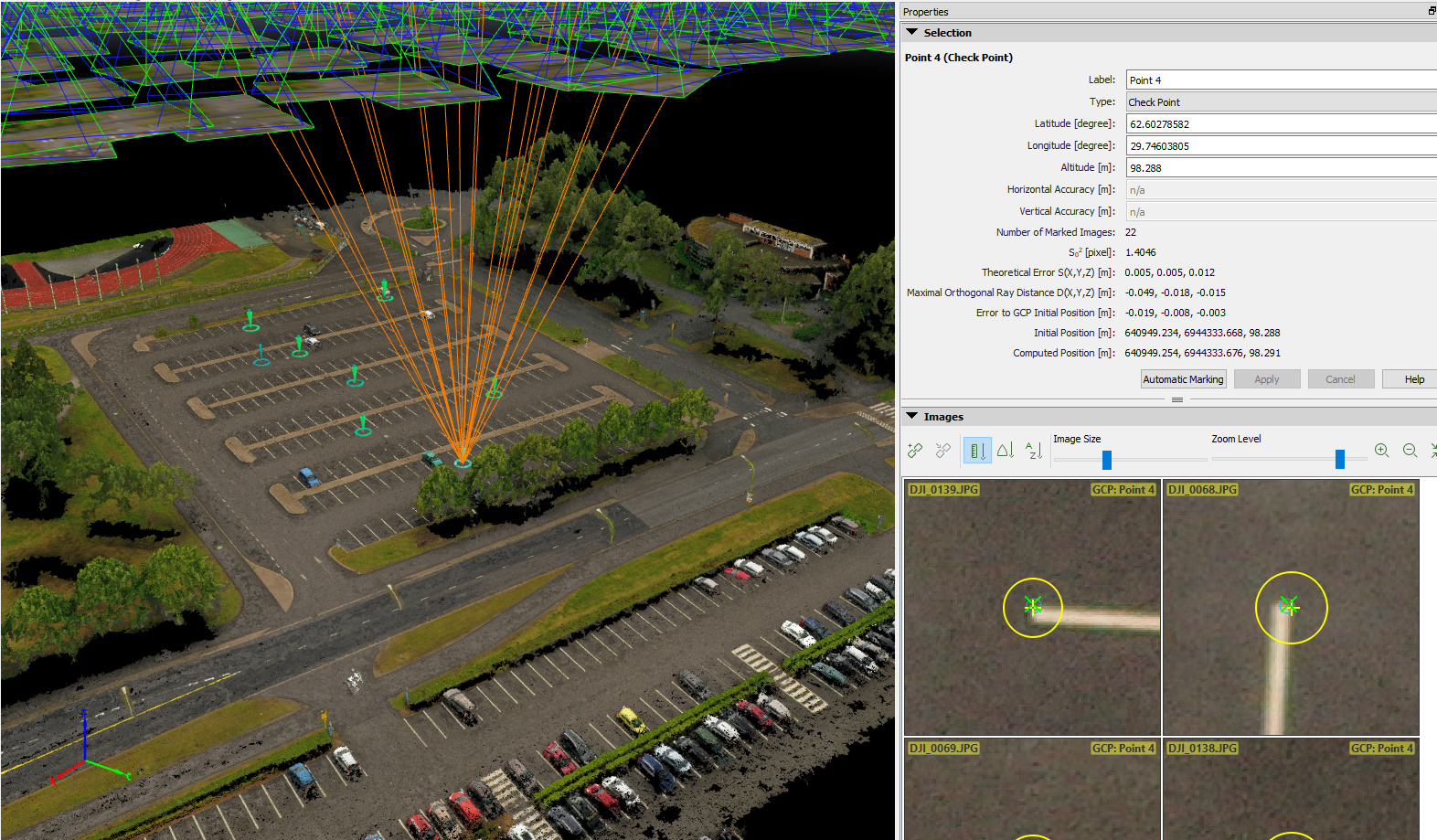
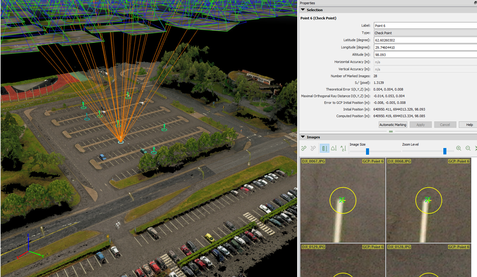


Pic. 6-12 Ground check points measuring to estimate the precision of the 3D model.
PROJECT 2. MINING SITE SURVEY ON MASBATE ISLAND, PHILIPPINES
Area of work was open pit with 50 meters depth. Steepness of the pit walls makes it almost impossible to use common RTK survey technics, while measuring by total station would make it possible to get results no earlier than few days after the start of field work.
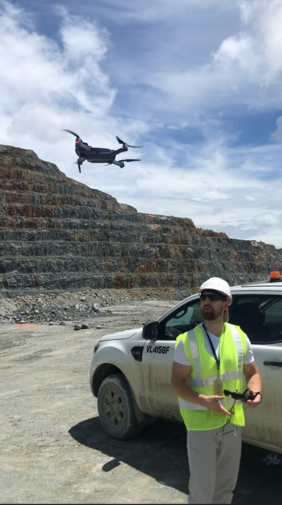
TOPODRONE SA team together with surveyors from mining company performed aerial surveying by a miniature survey drone DJI MAVIC 2 PRO PPK with additionally installed a high-precision Emlid Reach M+ on board and Emlid Reach RS+ GNSS receiver as a base station.
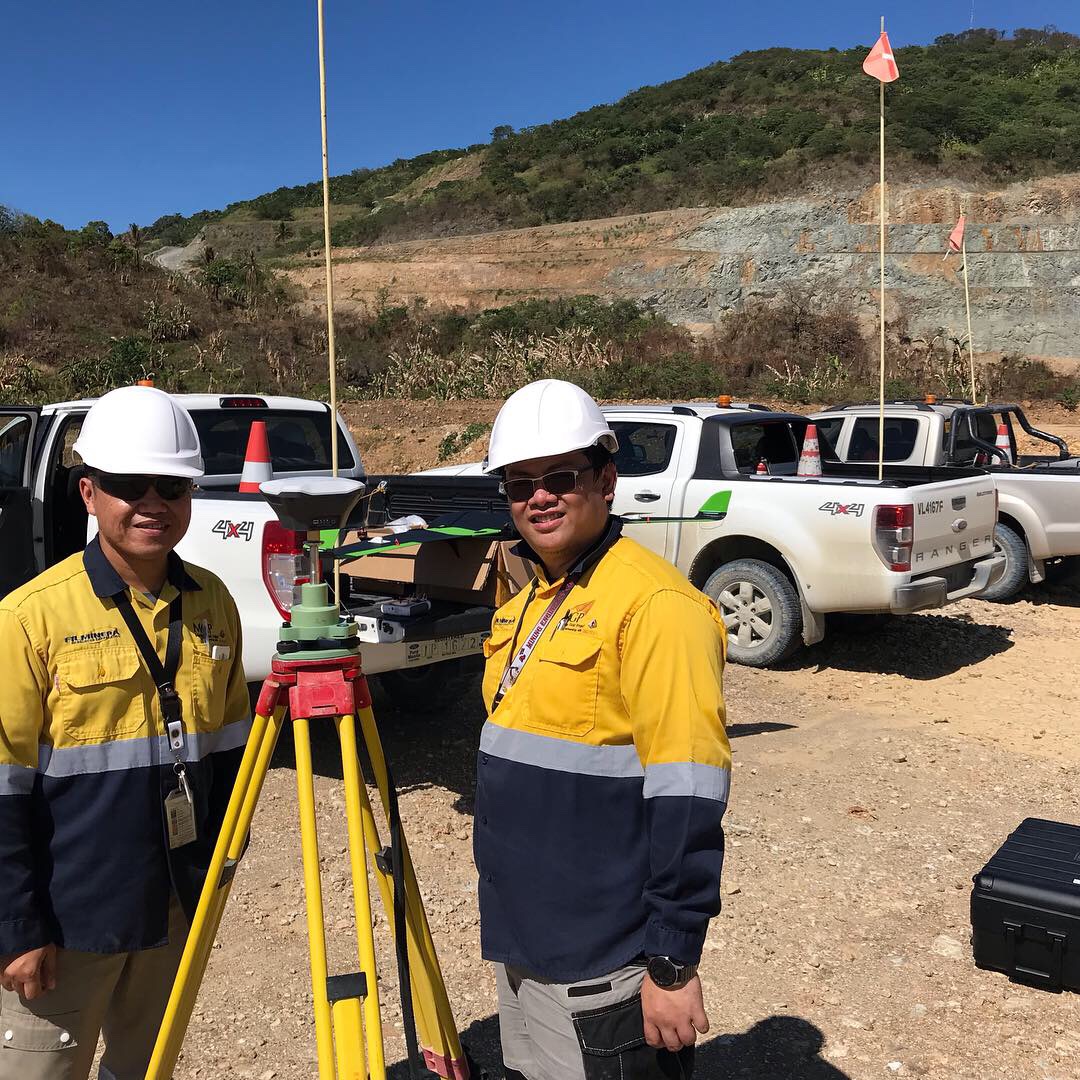
Pic.1 EMLID REACH RS+ installed as a base station
The flight time was no more than 20 minutes, aerial survey was carried out fully automatically, at 90 meters altitude. Flight routes were planned taking into account the double-grid technology, which allows to obtain more detailed textures of steep surfaces.
After field works, the following dataset was obtained:
- Set of photos from the drone
- Raw GNSS data from the drone and the base station in Rinex format
- The coordinates of the measured ground control points that were used to assess the accuracy of the model
As a results of the GNSS data post-processing in RTKLIB & TOPOSETTER software, high-precision coordinates of the image centers in the WGS 84 were calculated and finally converted to the local coordinate system of mining site using LGO software.
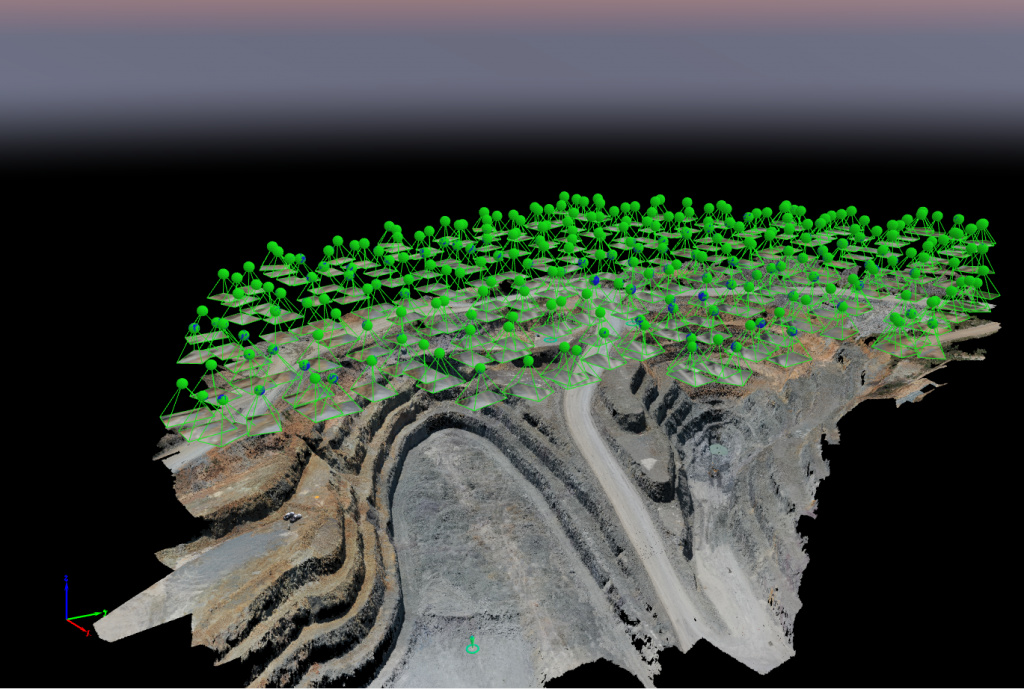
Pic2. Pix4D photogrammetric processing
PIX4D software was used for photogrammetric image processing. PIX4D photogrammetry software provides all messerly tools for precise images processing as well as images rectification, points clouds, DTM, DSM and TIN models generation.
Data processing didn’t take a lot of time and was very easy. We just added set of images with accurate coordinates to the project and ran the fist step of aerial triangulation.
Once initial the block triangulation was done, 3 ground control points were imported to the project to check accuracy. Total RMS error was no more than 4 cm. You can see results against GCPs in Tab.1
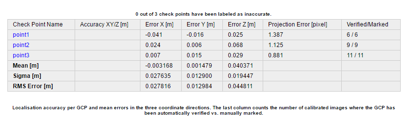
Table 1. Report on the assessment of the accuracy of determining the coordinates of control points
After aerotriangulation stage, automatic process dense cloud generation, creating a TIN model and contour lines was performed.
As a result of the project we generated high precision dataset of points cloud, TIN model and orthophotomosaic over hard to reach open pit area.
Thanks to the combination of affordable REACH M+ & DJI MAVIC 2 and advances PIX4D processing technology we substantially decreased number of field works and It took us just few hours to get accurate final result for volume calculation.
If you have any questions concerning Reach M+ integration on DJI MAVIC 2 PRO, DJI PHANTOM 4 4 PRO, DJI MATRICE 200, DJI INSPIRE, don’t hesitate to contact us at www.topodrone.org
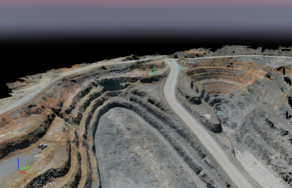
Pic2. Dense point cloud
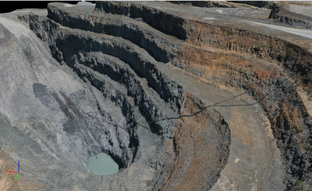
Pic3. Dense point cloud
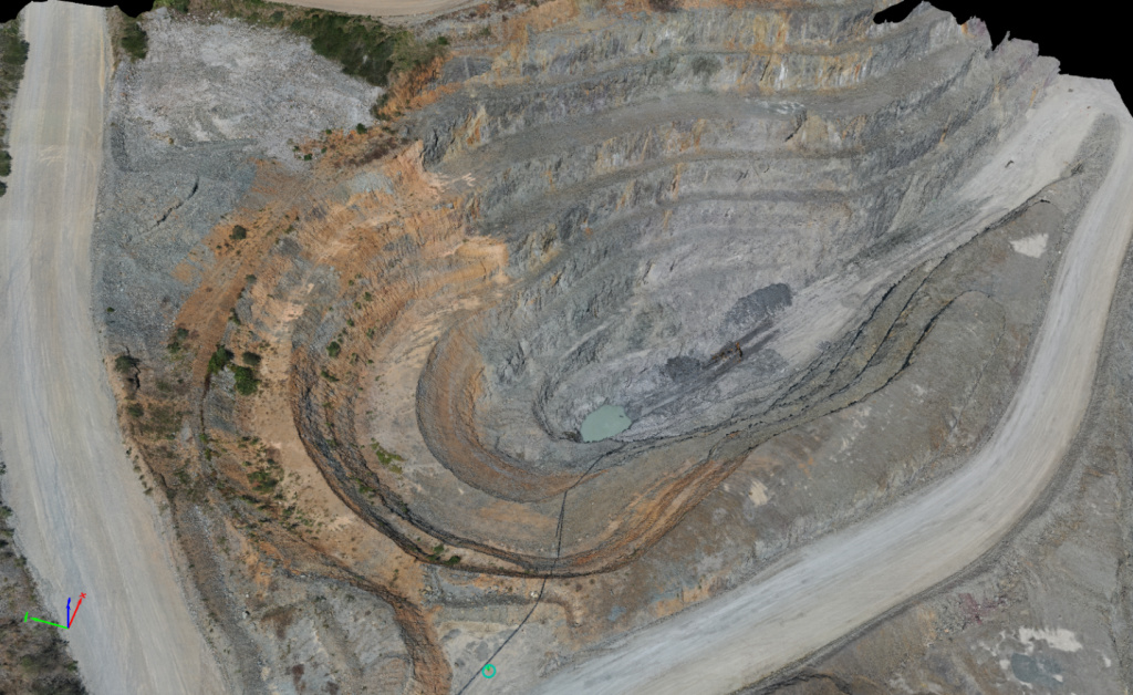
Pic4. Dense point cloud

Pic.5 Comparing accuracy against GCP
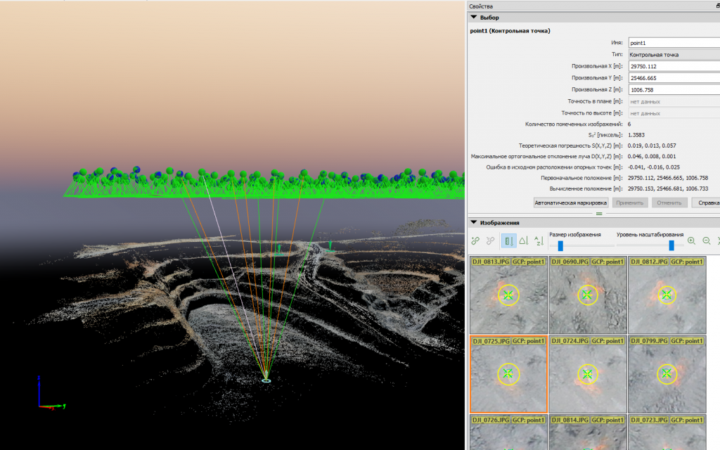
Pic.6 Comparing accuracy against GCP
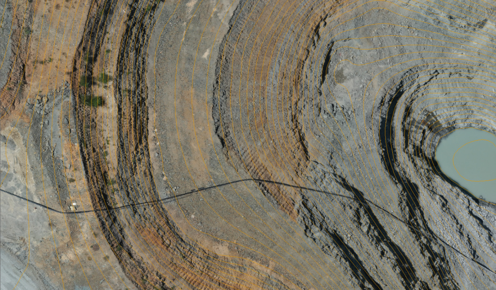
Pic. 7 Orthophoto combined with contour lines
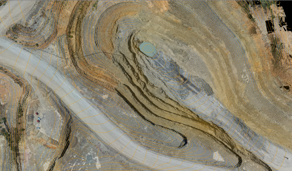
Pic. 7 Orthophoto combined with contour lines
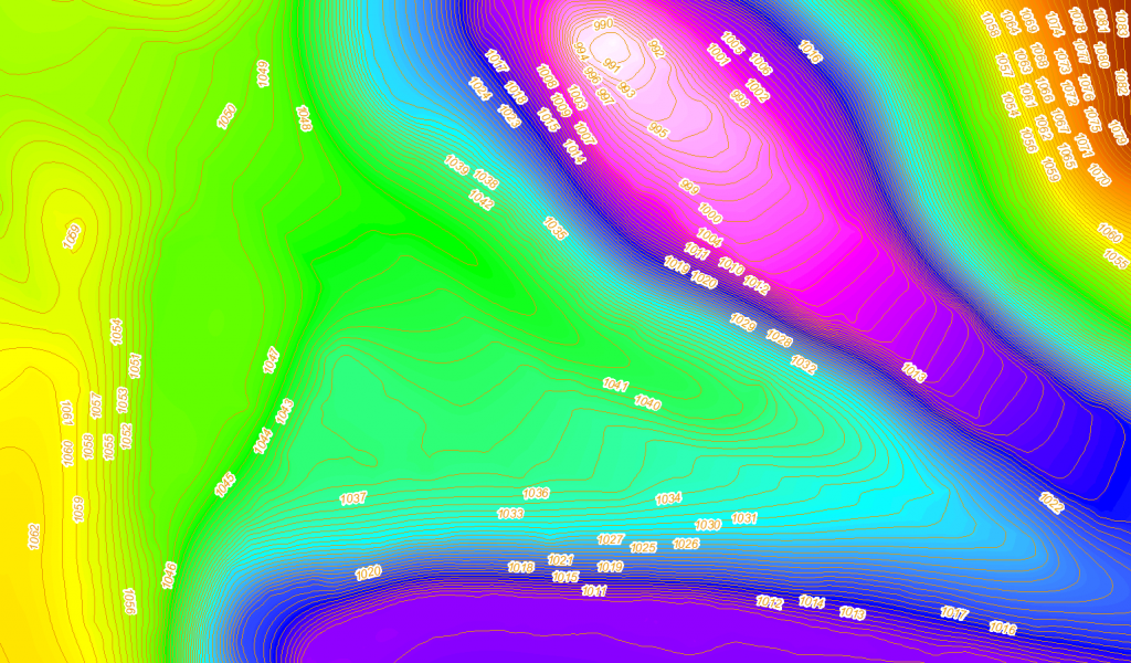
Pic. 8 DEM combined with contour lines

