PPM-decoder problem

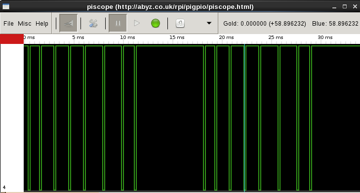
I’m having some problems getting the PPM decoder to work and was wondering if anyone could provide some insight. I am using a signal converter from fpvmodels for the PWM to PPM conversion (). I verified the output from the converter using an oscilloscope and noticed a few differences between the oscilloscope output and the definitions in the PPM.cpp example file. The ‘ppmSyncLength’, which I’m assuming is the time between repeats of the concatenated PWM signals, is 7ms instead of the 4ms defined in the file. The number of channels was also different as I only had 5 inputs (The output PPM signal from the converter is dependent on the number of channels connected unless it is less than 5).

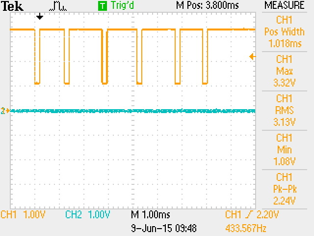
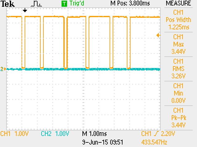
After changing ‘ppmSyncLength’ to 7000, ‘ppmChannelsNumber’ to 5 and ‘float channels[8]’ to 5, the output to the console is just a flashing cursor. It appears the execution is hung up somewhere before the if statement for console output (‘verboseOutputEnabled’ is set to true). Doesn’t matter if I wiggle the sticks on the transmitter or not. Also the peak to peak voltage is only 3.13V even though the input voltage is 5.25V, not sure if this is a problem or not.

Is there something else that needs to be changed in the PPM.cpp file for this to work with this converter?

Apparently the link to the signal converter didn’t go through.

http://www.fpvmodel.com/rmilec-high-precision-pwm-ppm-sbus-signal-converter-v2_g478.html

Hello Lars,
Since most PPM outputs are 5V we’ve added a voltage divider to the PPM Input to protect RPi’s GPIO. Yours is 3.3V but it still gets divided making it lower than 3.3V.
If you’d like to use 3.3V PPM input, you can remove resistor R8 at the bottom of the Navio board, it will disable the voltage divider. But remember that after that you cannot use 5V PPM input or otherwise you will damage the RPi’s GPIO.

1 Like

That solved the problem! Just for future reference, what is the value of R8?

R8 is 470 Ohm

Now that the example code is working, I moved it into my data acquisition script but upon execution it never actually runs the entire script. It appears the interrupt keeps the program in the read PPM function and never executes anything else. Is there a way to run this in the ‘background’ or sample the PPM port on demand? Would using a separate thread to read the PPM values work?

Yes, a separate thread (std::thread, pthread) should work without a problem.
Also, pigpio library provides pipe and socket interfaces that can be used for reading the gpios, check the prototype code we’ve used in the ardupilot - https://github.com/emlid/ardupilot/blob/navio-experimental/libraries/AP_HAL_Linux/RCInput_Navio.cpp

I added a separate thread for the PPM reading based on the multithreaded barometer example but keep getting the error

error: invalid conversion from ‘void ()(int, int, uint32_t) {aka void ()(int, int, unsigned int)}’ to ‘void* ()(void)’ [-fpermissive]

I’ve tried changing the inputs to the PPM function from the way they are in the example file to

void *ppmOnEdge(int *gpio, int *level, uint32_t *tick)

but seems to give the same error whether or not the pointers are used. Any ideas?

Also, not sure about the general layout of the program but I have it laid out as follows:

  • Include
  • Definitions
  • ppmOnEdge function
  • Main program
    • GPIO setup
    • Create thread
    • while loop to display channels

Hello Lars,
Have you been able to solve the issue?
I’d suggest to use the pigpiod pipe code from the APM I linked before, it should be easier to use in multithreaded environment.

I have not solved the issue yet and I think I’m starting to figure out that I have no idea what I’m doing. I went back to the link you sent and looked at the code. I downloaded the entire ardupilot library from the github site and created a new file inside the “libraries” folder where the original file is that you pointed me too. Starting without the multithreading (just to get stuff working first), I tried adding the functions as well as a simple “main” program that does the same thing the PPM-decoder example did … sleep. Compiling it gives errors that it can’t find .h, I find the file and include the full path to the file, that fixes it and then another file can’t be found. Everytime I fix one, another one can’t be found. I have a feeling that this is not the way its suppose to be. For the time being, I think I’m going to abandon this and work on some other aspects of the project until I can learn more about programming in c++.

Well, in case its any use, I’m using the PPM example on my quad. function and variables are:
unsigned int samplingRate = 1; // 1 microsecond (can be 1,2,4,5,10)
unsigned int ppmInputGpio = 4; // PPM input on Navio’s 2.54 header
unsigned int ppmSyncLength = 4000; // Length of PPM sync pause
unsigned int ppmChannelsNumber = 6; // Number of channels packed in PPM
bool verboseOutputEnabled = false; // Output channels values to console

float channels[8];
unsigned int currentChannel = 0;
unsigned int previousTick;
unsigned int deltaTime;

void ppmOnEdge(int gpio, int level, uint32_t tick)
{
if (level == 0) {
deltaTime = tick - previousTick;
previousTick = tick;

	if (deltaTime >= ppmSyncLength) { // Sync  
		currentChannel = 0;  
		}  
	else  
		if (currentChannel < ppmChannelsNumber)  
		{  
			channels[currentChannel] = deltaTime  
			currentChannel++;  
		}  
	}  

}

initialisation is (put this in main at the start somewhere):
gpioCfgClock(samplingRate, PI_DEFAULT_CLK_PERIPHERAL, PI_DEFAULT_CLK_SOURCE);
gpioInitialise();
previousTick = gpioTick();
gpioSetAlertFunc(ppmInputGpio, ppmOnEdge);

you also need to
#include <pigpio.h>
at the top of your program somewhere and adjust the number of channels and you should be able to read channels[channelnumber]
Ardupilot example will use the same amount of CPU power, but be more process safe, but it does need a little modification to work outside of ardupilot.

After some additional research and testing I was able to get the PPM decoder working in a separate thread. For those looking to run the PPM decoder outside of ardupilot, here is the code. Turns out it was a simple modification of the original PPM decoder program once I had a better grasp on threading. Keep in mind that the ‘Options’ will need to be adjusted based on your system.

#include <pigpio.h>
#include <stdio.h>
#include <unistd.h>
#include <pthread.h>

//================================ Options =====================================

unsigned int samplingRate = 1; // 1 microsecond (can be 1,2,4,5,10)
unsigned int ppmInputGpio = 4; // PPM input on Navio’s 2.54 header
unsigned int ppmSyncLength = 7000; // Length of PPM sync pause
unsigned int ppmChannelsNumber = 5; // Number of channels packed in PPM

//============================ Objects & data ==================================

float channels[5];

//============================== PPM decoder ===================================

unsigned int currentChannel = 0;
unsigned int previousTick;
unsigned int deltaTime;
int arg=0;

void ppmOnEdge(int gpio, int level, uint32_t tick)
{
if (level == 0) {
deltaTime = tick - previousTick;
previousTick = tick;

    if (deltaTime >= ppmSyncLength) { // Sync  
        currentChannel = 0;  
    }  
    else  
        if (currentChannel < ppmChannelsNumber)  
            channels[currentChannel++] = deltaTime;  
}  

}

void * PPMDecode(void * args){

// GPIO setup  
gpioCfgClock(samplingRate, PI_DEFAULT_CLK_PERIPHERAL, PI_DEFAULT_CLK_SOURCE);  
gpioInitialise();  
previousTick = gpioTick();  
gpioSetAlertFunc(ppmInputGpio, ppmOnEdge);  

}

//================================== Main ======================================

int main(int argc, char *argv[])
{
pthread_t PPMThread;
if(pthread_create(&PPMThread, NULL, PPMDecode, (void *)arg))
{
printf(“Error: Failed to create thread!\n”);
return 1;
}
while(true)
{
printf("%4.f %4.f %4.f %4.f %4.f",channels[0],channels[1],channels[2],channels[3],channels[4]);
printf("\n");

    sleep(1);  
}  
  
pthread_exit(NULL);  
  
return 0;  

}

Finally upgraded to Navio+ and RPi 2 and having some PPM decoder issues. Everything functions with and RPi B and original Navio. I literally replaced the the Pi with a Pi2 and Navio with a Navio+ keeping everything else the same. I noticed that the PPM-decoder function no longer works, even after I deleted it and got a fresh copy from github. The only change I made to it was to set the PPM sync to 7000 and channels to 5 to match the PWM-to-PPM decoder I have. I added some print statements to the code and it makes it into the while(true) loop but never makes it into the PPMonedge function. Checked the PPM output of the decoder with an O-scope and it is functioning normally, providing a 3.3V signal. On the original Navio I had to remove R8 to get the PPM decoder to work but according the blog post on the Navio+, it is both 3.3 and 5V compliant. Any ideas why moving to a Pi2+Navio+ would cause the PPM decoder to fail?

Used a multimeter to verify all connections and it appears everything is ok hardware wise. The traces between PPM and IC10 and IC10 and GPIO4 checkout. It appears that AUX also goes into IC10, what is AUX used for and what is IC10?

I connected an o-scope to GPIO4 to see what was going into the Pi and also to the PPM encoder alone to see what it was putting out. I noticed a difference between the PPM encoder output when it was connected to the Pi+Navio and when it was left disconnected. Figure 1 shows the output when connected to the Pi+Navio and Figure 2 when disconnected. The big difference is that with the encoder connected, the PPM signal doesn’t get pulled down to 0, instead to ~1V. I looked up the voltage thresholds on the GPIO connector and there seem to be a range of answers. The most general answer I found states that the threshold is on average 1.8V but can range anywhere from 0.8 to 2V. Some people also applied various voltages to the GPIO pins and read their states and 1V still produced a high reading. If that is the case, then it looks like IC10 is preventing the PPM signal from going low enough to register a ‘0’ and therefore no PPM can be read … or maybe the PPM decoder doesn’t do well under load, don’t know.

Is there a PPM encoder that is recommend for use with Navio+? Would it be possible to bypass IC10 since the PPM signal is already 3.3V?

Narrowed it down to either the logic level converter or the PPM-encoder itself. Since the encoder outputs a 3.3V signal, I connected it directly to GPIO4 without the Navio+ attached. Ran the PPM-decoder example and it gave back the correct pulse widths so its not a software issue. This means either logic level converter is not functioning properly or the PPM-encoder output is dependent upon the connected load.

Can you provide a schematic for the PPM circuit?

@larssoltmann it is NXP NTS0102GT logic level converter, it actually the only thing in the way of PPM signal. You can connect PPM directly to the GPIO if it is 3.3V. We have never experienced any issues with level converter, but if it is faulty we will gladly replace the Navio+.

I also have problems getting the RMILEC ppm encoder to work with Navio+.

When attaching the 3V output from the RMILEC ppm directly to GPIO4 on Raspberry Pi 2, then I get a nice signal from 7 channels.

But with the Navio+ attached, there is no proper ppm signal getting through anymore. However, when attaching one PWM channel with 5V from the receiver to the ppm input on the Navio+, that signal gets displayed properly in piscope, so the ppm input on the Navio+ does work with 5 V but not with the 3V from the RMILEC ppm encoder.

That is the exact same behavior I was witnessing as well.

I obtained a different PPM encoder (Geeetech PPM module) that has a 3.68V output (according to the oscilloscope) and it works with the NAVIO+. I haven’t scoped the output of the NAVIO+ with the Geeetech encoder attached so I don’t know how it compares to the RMILEC output. I suspect that the NAVIO+ is altering the output the of the RMILEC encoder since it never gets fully pulled to GND when the NAVIO+ is attached. Perhaps the encoder is expecting a certain load that the NAVIO+ is not matching.

Now I got the RMILEC ppm encoder working after attaching the ppm output signal directly to GPIO4 and at the same time completely disconnecting the GPIO4 from the Navio+ board.

This was easily done without soldering or otherwise damaging the board, just by carefully pulling out the pin to GPIO4 from the extension header (you can push it back again, if you want) and attaching a wire instead.

We will order a RMILEC encoder and test it. The logic level converter has internal 10k pull up, but I do not see how an MCU is not able to pull 10k down.