I am trying to get more surveying use out (initially setting GCP’s) of my Emlid solutions and have had a specific scenario pop up a few times recently that I am trying to work around.
We started using our drone to capture topographic information for our pre-bid services and at that stage we have very little or no information to come off of. Because of this I have had to do localizations to keep my surveys on the same basis as the information we have been provided by the surveyors/engineers. I have finally found good solutions to go from ellipsoid to Geoid, but that obviously doesn’t match what is in reality on the ground as was thoroughly discussed in this thread.
Question is if I convert my Ellipsoid values to GEOID and then use this tool to get my orthometric heights does the offset to the GEOID remain consistent enough in a localized area to make the calculated orthometric heights truly relative? Or is there another way to get true angle/distance measurements from the base in Reachview? My initial experience is no on both scenarios.
Ellipsoïd to Geoid height is the main problem with GNSS. You have to rely on global models (Mainly EGM 2008) or local refined models (we have that here for dam projects by example). In both case have a look on the correction slope (ie mm/km) to evaluate how far from base you can consider the correction as a constant value.
If your job requires high Z accuracy, nothing can compare with survey leveling techniques you will have to run.
Calculate property corners and know control points (horizontal) in CAD
Locate PROCOR’s and CP’s on the ground with a localization
Run a level-loop through any vertical benchmarks on the plans
Tweak the elevations in the localization to match the level loop
The main difference is that the Topcon setups and data collector software we use relative angle/distance from the base to establish the YXZ coordinate that is used to compare to the calculated position. In the localization the GNSS Lat/Lon is associated to the YXZ of each of those points and we then have the residuals of the calculate network vs the localized network. This then allows us to identify any points on the ground that vary outside of our tolerance and choose whether or not to use them for horizontal and/or or vertical control.
This is a far departure of what these solution with GIS software are capable of. After some more research and testing in my area across a 50 mile radius all of the separations were within about 10ft of each other, but within a 1 mile region of which most of our projects would fit in the deltas were within 0.5ft with the worst in hilly areas being 1ft. I guess the main goal I am trying to accomplish has more to do with the box stock Reach solution and how to get relative ground elevations. I can typically find at least one monument to reference to which I am trying to emulate the way Topcon acquires relative information and I can’t figure out how to do it with Reachview.
This besides not being able to do localizations is the reason I have been running MicroSurvey FieldGenius, but my effort to deploy these to our construction field crews for simple topo collection for work performed calculations and grade stakeouts really needs to simplify the solution and hopefully get to the box stock setup. In these efforts horizontal really doesn’t matter.
It gets messy when we start getting into the technicalities, but hopefully this explains it a little better.
i have used that tool and it works fine. I am in California and old published benchmarks dont mean much, you need to re-observe against CORS if you want accurate elevations. I have found the RS units to do a fine job of maintaining relative elevation accuracy within a few centimeters compared to our total station and OPUS points, but only in open sky conditions.
That would be the same problem I am having by using a local base and rover. The horizontal would be better, but the elevations would be off the ellipsoid and not relevant to actual ground. How are you getting the ellipsoid values to a relevant ground level-looped elevation basis?
What are you doing to marry the control of the two methods? I am guessing that the control you are using for your TS came from the same place as and matches the CORS.
There is just something I am missing about this type of GNSS surveying.
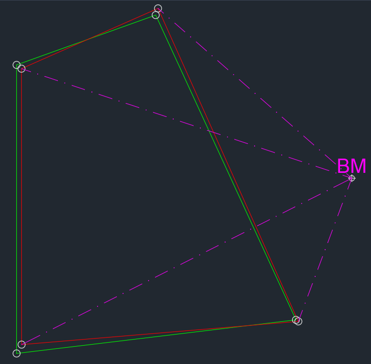
In an effort to explain a little better our problem that is solved by localization and why we need to establish our GCP’s by angle/distance. Horizontal is fine because we have the “BM” with an established coordinate and vertical. Sometimes this is just a control point (horizontal) and have to come off an actual benchmark (vertical) - by our terminology.
Green is the CAD/Record/Plat boundary. Red is the boundary located via GNSS and associated relative horizontal distance, but the vertical is is one place per GNSS ellipsoid, another via GEOID, another vs the Orthometric calc and the one that is relevant to use which is the actual ground leveled elevation. In this instance (most common scenario) the BM has a known GNSS and Surface coordinate.
i am not marrying them in the field which is probably what you have to do, due to the nature of your work.
i have read many of your posts in the past and have come to the conclusion that your job requirements are complex (maybe substantial is the word?) due to the nature of your work. my work is more straight forward i think.
I also do not have access to many of the commercial software packages that are out there to do this sort of work so i have had to build some tools and work with what i have.
so for me, here in California, bench marks are dead.
the only source for accurate elevations is to do OPUS and to do three to four hour observations to get a result that can be repeated. and so the only ingredients you need are a very accurate height relative to the ellipsoid (e.g. 26.445 ) and then a geoid value for that location …
i use two IGAGE receivers (x90 and IG3) to log data, simultaneously on two control points, for three hours which i then send through OPUS. i dont personally use the total station, two of my coworkers do that. its a new topcon robot. so i do the OPUS points and hand them the two points telling them which is the primary, the other creates what my co workers refer to as the basis of bearing for their end of the job. thier product is topo points so they are not working within a plan or retracing a deed or doing stake out.
since we dont have to be on the same page so to speak while we are out in the field (i think this is where your situation is probably different) then i capture points in wgs84/ITRF/IGS08 and ellipsoid height. then back in the office i run them through HTDP to get them into NAD83(2011) and then calculate the elevations based on GEOID12b and GEOID18.
where we usually screw up is in the combined scale factor and the convergence factor since i will need thier ground shots to be transformed to a grid like state plane.
I’m not sure if I’m missing something, but couldn’t you set your base on the benchmark for which you know the orthometric height and set the elevation manually to that value?
Wouldn’t the rover then get corrected relative to the base elevation and give you orthometric heights for your GCPs in real-time?
It varies per project, but is typically outside of our tenth of a foot tolerance for the benchmarks from the engineer. Remember we’re talking about construction and not surveying. That’s what they leave us to build by and we do it darn well.
i dont know, in non obstructed environments, i end up with values from the RS+ that are always within 5cm of my OPUS control vertical value and more often than not within 3cm.
I think what you are missing is that land surveyors in our area and construction processes never use GPS for vertical datum. This means that all vertical benchmarks are traversed in from LCRA and TXDOT monuments. Traversed with a level and grade rod. All control local to the site is verified with robotic total stations. It’s fine whatever OPUS says and what your GNSS says, but it is not ground truth. It’s all still based on theoretical calculations. We can’t build to 1/2" and sometimes 1/4" tolerances with even 3cm datum.
That’s what I understood and my suggestion assumed you’d have a local control for which you know the orthometric height (to a degree you are satisfied with). So am I getting it right that your question was about finding your control’s height or are you looking to know if the relation between your control and your GCPs is reliable?
I don’t think I have an answer for you but this might clear up the question at hand for others.
i get it, i hear you, and from what i can ascertain (i am not a surveyor) that makes sense for most land surveys and construction projects. really why would a property resurvey or construction project even really care that much about their “true elevation”? seems like you would be better off focusing on maintaining high relative accuracy within your project site, which sounds like in your case means levels and total stations, and tying into local control.
for “true elevation” it seems like the world is changing in this subject. this article, which is a few years old, i thought was pretty informative…
my take away from that article is that elevation (i am in the U.S) is progressively going to be based on CORS.
in a practical sense, a number of the locations i end up at are back in the woods. i can spend hours finding and researching some old monument to try to get a elevation value or i can just do three hours of data and go through OPUS. and if i do that OPUS observation on a old benchmark i can submit to NGS for inclusion: https://www.ngs.noaa.gov/GPSonBM/
my hope is that i end up with a RTK base (RS2 or other) that i can log data on, while doing RTK, then OPUS my base raw file to get a more accurate location for where my base was, then i can just shift my days RTK work to improve absolute accuracy.
I think you have it here. I am trying to see if the Emlid equipment without any additional software can work on the same elevation basis as our localized network. Orthometric heights are not terrain elevations. I don’t understand how people are “Land Surveying” with elevations that don’t represent the land. I feel like I am missing something.
This makes it pretty obvious that the type of use by the majority of the people that are happy with orthometric heights has nothing to do with true land surveying and engineering as is defined in the industry that I have been working in over the last 20 years. It solidifies my understanding that this type of case is a GIS solution trying to become a Surveying/Engineering solution which also seems reflected in allot of the feature requests across these threads.
If you cannot be terrain relevant in elevations then you cannot design a drainage system that will fall at the right percentages and/or arrive at the correct elevation of an outfall or spillway somewhere further down the line that is not part of the project. I have to be relative to B to be able to design a 5% fall or slope from A to B. We also have to know true terrain elevations so that we don’t build inside of flood plains. An orthometric elevation difference of even 3-feet from the true ground elevations could render a complete tract useless as it would all be in the floodplain and unbuildable. Does that make sense?
I totally agree with the need to have a global (national) reference system that is used by all, but it may take more than my lifetime for all the old projects that weren’t surveyed on that coordinate system to flush out and for the new system to become the enforced standard so that all newly surveyed and engineered projects moving forward work together. They still have an issue with vertical though when the whole solution does not account for local elevations. That is unless all previous vertical datum is thrown out the window and every project starts to build using GNSS elevations.
Essentially what you are trying to do is take a known elevation from a local bm and tie the rest of the ground elevations from the reach to that plane. Is there a way to do this with field genius?
I hate to say it but the more time I spend on here and with the units I just got, the more I think it may have been better to get a unistrong or south galaxy full survey kit off alibaba. It sucks the existing software still does not have the capability to do land survey work. If you have to go outside the box for that kind of software solution, it starts getting expensive. At my last firm I was a big proponent of trying these units out for photogrammetry, now that I finally got ahold of a pair I am concerned the work flow just isn’t right for land survey here in the states
If anyone has any input on this I would love to hear it. I really want to get this system up and running to do small topo/boundary/aerial work paired with my robotic ts.
Yes, FieldGenius allows for localizations. I went from the Windows CE to the Android version and it is fantastic. I got it pretty early so I am not sure how much they are charging now. You can download a 30-day demo.
Thanks for clarifying. You seem to be the only other survey professional here in the states doing the same things I am trying to do. Would you say with field genius you are able to do the same work with these reach units as you are with the equivalent from trimble/spectra/lieca/topcon?
Can you give a quick summary of all the things you are able to do with these units running field genius?
I am looking to do:
topo tied to the California state plane system
Set control to establish a known real world NEZ in state plane
Use existing city BM horizontal and vertical for base coordinates in US survey feet
Set GCPs for a drone in state plane with true ground elevation based on existing control
I have been lurking this site for some years now and it is hard to get a handle on those out in the US trying to use these units for more than GIS applications. Any light you can shine on your experience would be immensely appreciated!
I don’t understand how “survey” softwares can’t have localizations because it basically allows you to put any coordinate system in relevance to another. That versatility seems to cover 90% of the problems we had with coordinate systems back in the day.
For those who aren’t familiar you have known points for your control network. As long as they are accurate in relation to one another you import them into the data collector, setup your base wherever you want, observe each known point which associates a GNSS coordinate value to whatever YXZ coordinate the point had and it then links all those points together in a network and provides the residual error of each point in relation to the others in the network. You take out the horizontal and/or vertical attributes of the points that are not within your required tolerances. Ours internally are 0.10ft horizontal and 0.07ft vertical so I uncheck anything over 0.09ft and 0.06ft respectively. You have then prorated out any error between the theoretical perfect coordinate and the real-world ground coordinates and whatever you build inside that network is perfectly fit and doesn’t have to be scaled.