Navio2 with Reach as second GPS

Not sure what “Image” you are reffering to ArduPilot was just installed, so the newest.

Navio2, Raspberry Pi3, Reach and Mission Planner

I simply want to use my reach unit in RTK fix mode as a second GPS. I’ve tried several configurations with no success. Help is scarce, VERY OLD and mostly PixHawk related.

Where are the experts here? I’ve been fighting this for a solid week! @emlid We’ve bought into your product with both the reach and Navio2, and yet ALL the docs and references I’m finding are REALLY old or are PixHAWK related,

First question, Where do you recommend the reach plug into the Navio2 and where is best to receive gps corrections from the base. I can think of and have tried at lest 4 possible configuration?

HELP!!!

Hey Mike. I have experience doing what you are trying to do.

First, let’s set some expectations: So far our partners have been doing mostly PPK (post processed) with the Reach. We have tried RTK but there has been too much churn over the last few months in all the code bases to provide any definitive answers re RTK in flight. In particular, the way RTK GNSS status is handled in ArduCopter and Mission Planner has changed. Not sure where it is now, but last I checked you needed a particular version of each to get accurate RTK status reporting. May not impact actual functionality of the GNSS but how you see it in real time via MAVLink. Anyway, what you want to do is doable, but I can’t guarantee RTK results as I have not seen it myself on a reliable and repeatable basis. Perhaps someone else on the forums has and can chime in.

Next, you need a really good antenna setup. We have been using Maxtenna helicals, but don’t have enough data to say if they are better than others out there. We wanted to get rid of the ground plane requirement to have a better chance for coverage while maneuvering. Minimum, you will need a good ground plane and it needs to be well clear of all sources of interference. Let’s just say 10CM clear in all directions as that is a figure some smart people have passed to me.

And this is the best doc your are going to get. It works if you follow it closely:

I have a copter in the shop to refurb for a customer and do some RTK/PPK testing. Won’t happen until June. Wish I could give you more definitive answers, but the tech is still green. I think most of us here are still learning as we go.

Thank you for the response @coby,

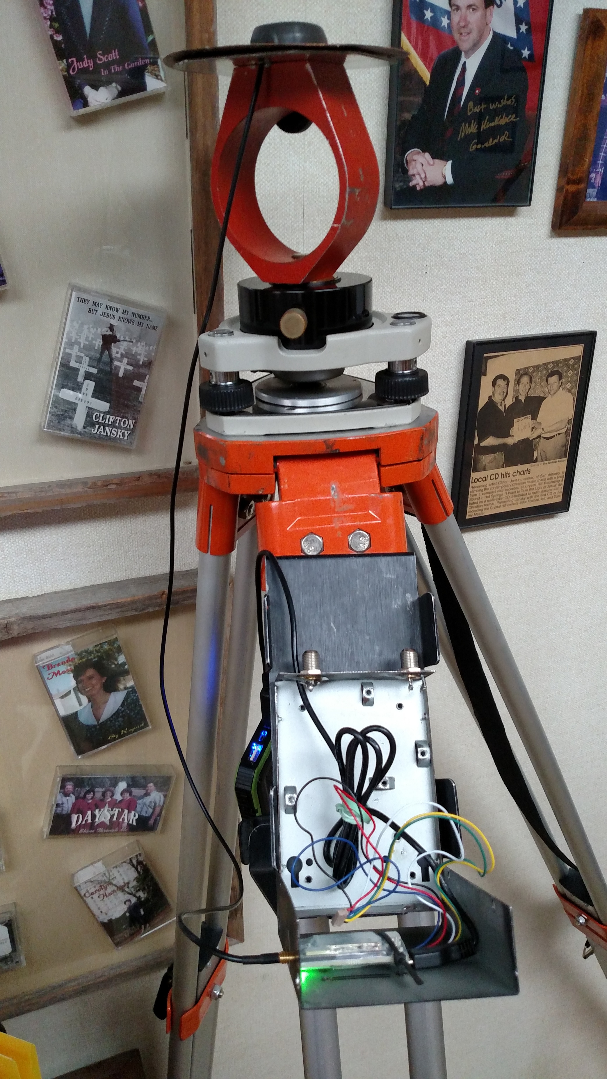
For both Reach units I have made my own Ground Planes

I’m taking this in steps, as a Land Surveyor, My first goal was successful GPS fix between Base station and Rover using two reach units. SUCCESS. communication link was two 3DR Radios. accuracy was within 2 centimeters.

Next goal, Base station at my office over a known point sending corrections out over the internet to my Rover (Again, using two reach units, again SUCCESS!)

Comunication Flow: NTRIP - Reach as Rover>WiFi>internet>My LAN>Snip>Reach as base

Base, using my LAN and was sending connections to my windows 10 Desktop, which was running a free NTRIP Caster called SNIP, which in turn was broadcasting the corrections over the internet.

For the Rover, I created a hot spot on my verizon Android Phone to provide access to the internet and NTRIP correction from Base. I was then using an Android Tablet running the App (MapIt), and connected to my reach rover via bluetooth to collect points. I did not check accuracy, but initial indications look to be in the same 2 CM area, providing I’m not more than 10KM from The Base.

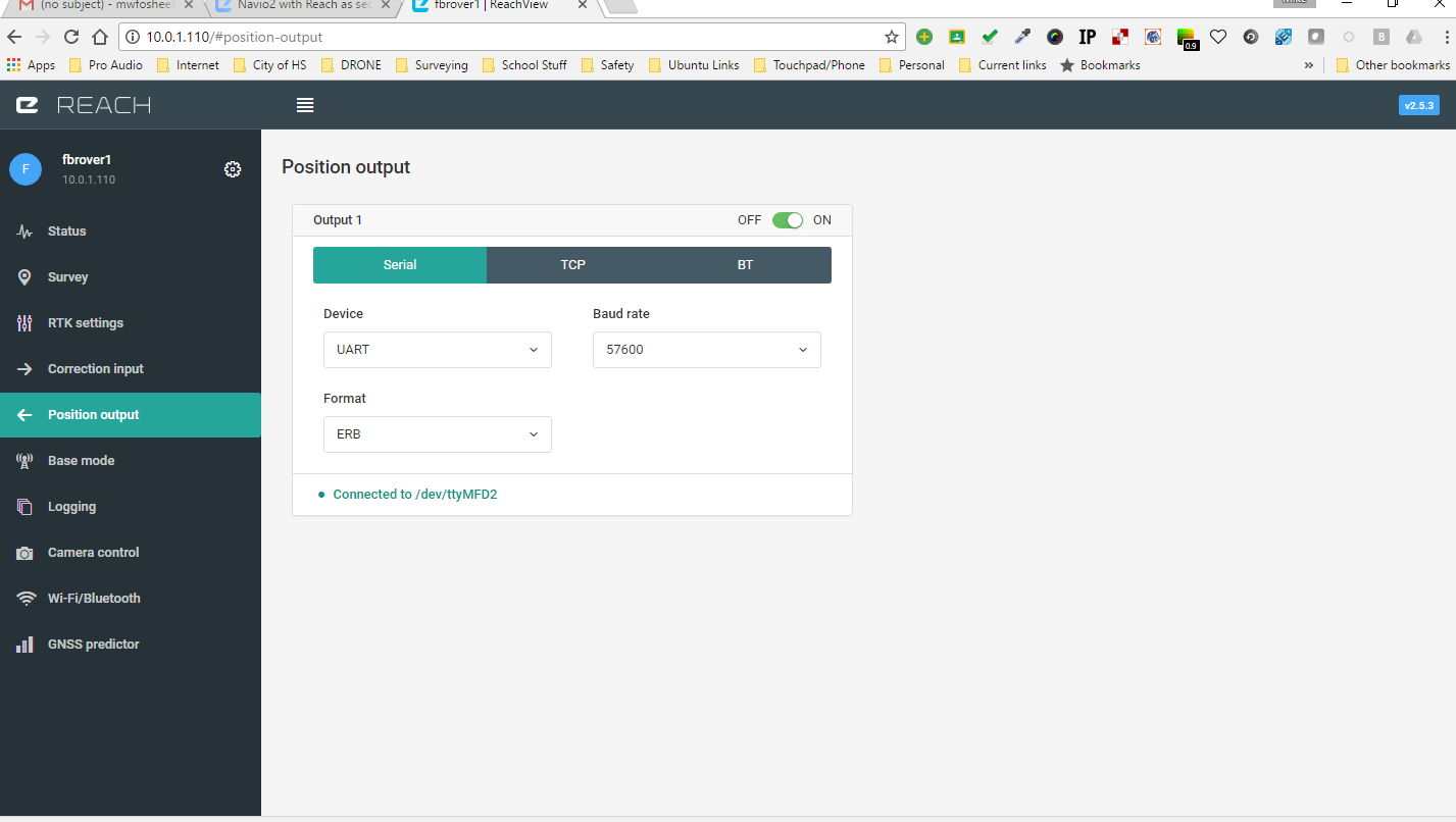
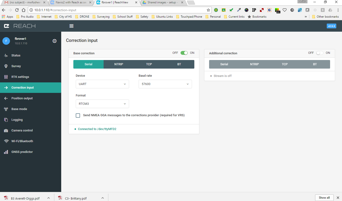
I wish to now add an additional reach unit as 2 GPS to Navio2 and I’m not sure which works best:

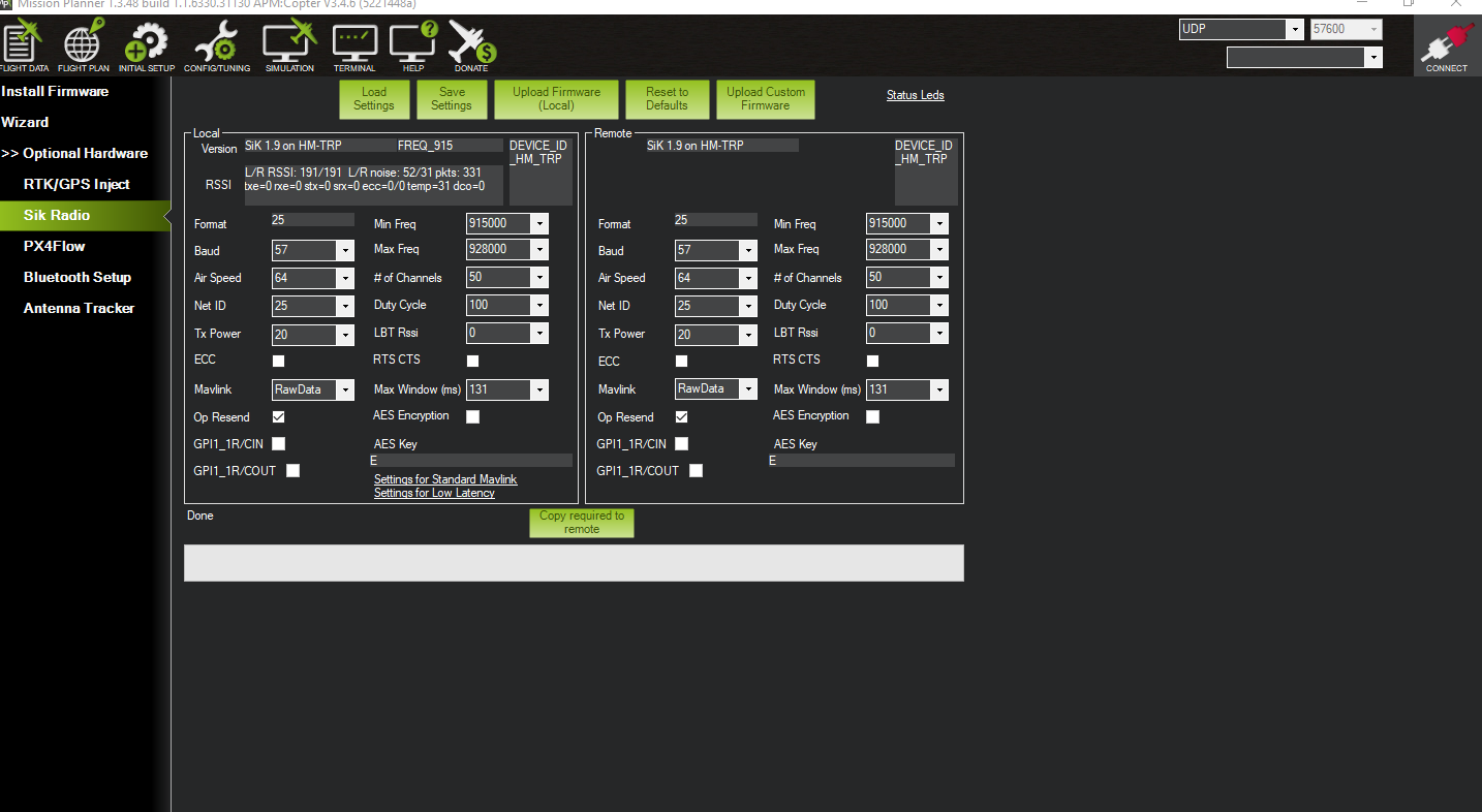
Run the rover/base setup just like before using separate radios, then simply add the reach as a secondary source for GPS or
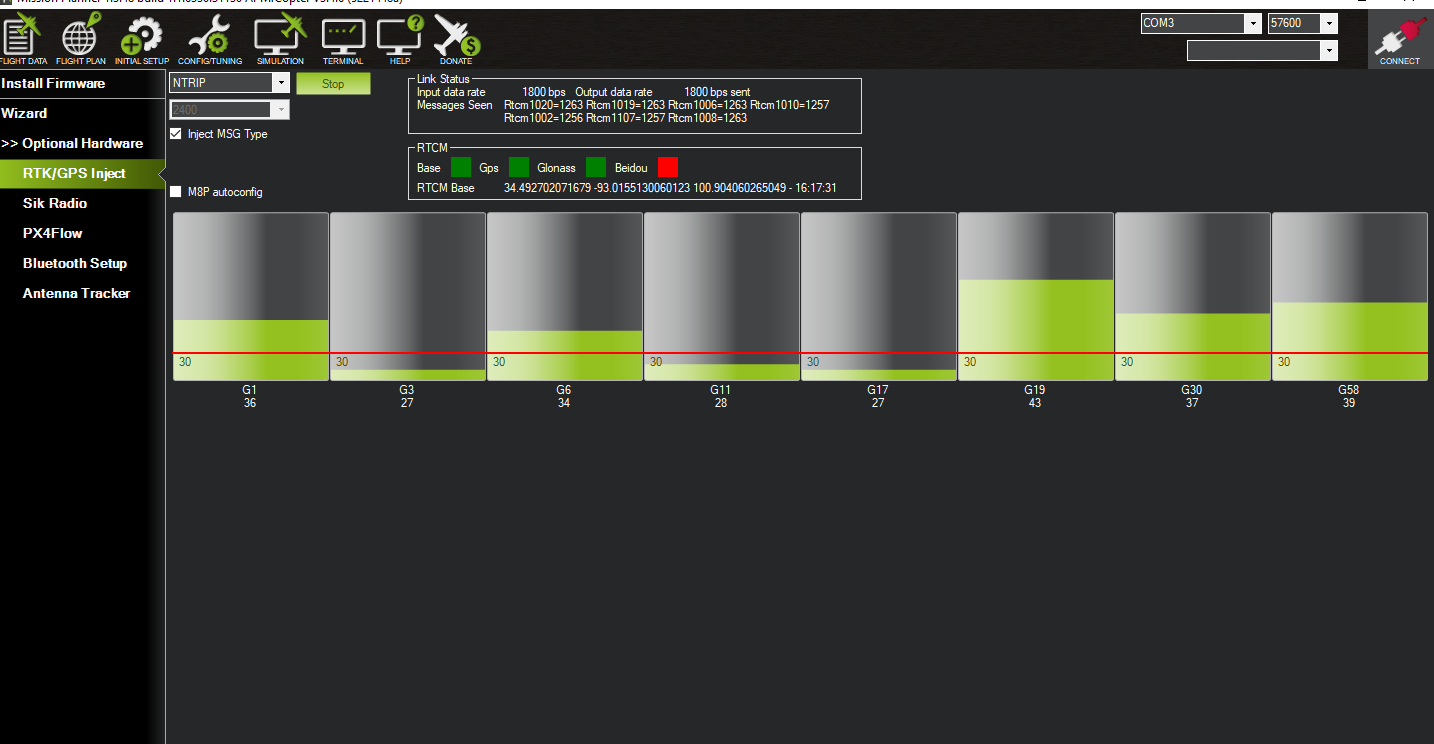
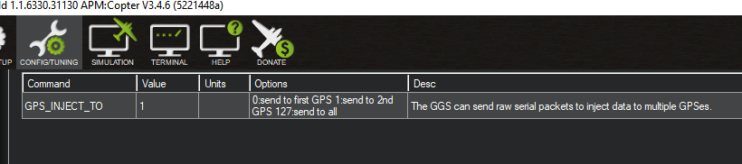
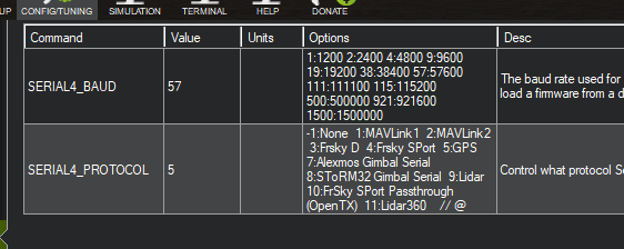
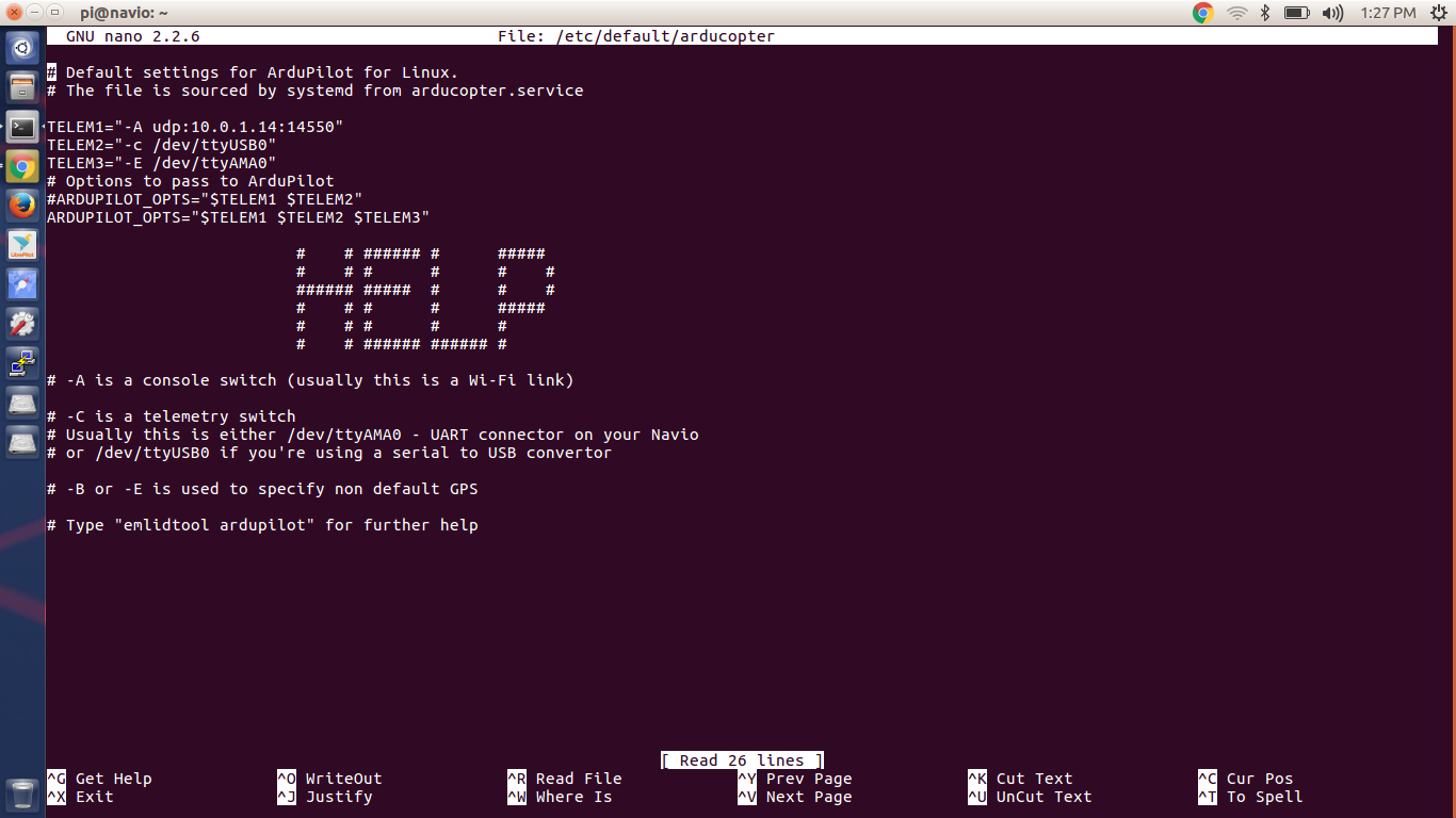
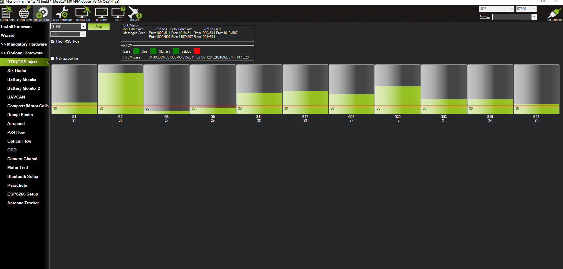
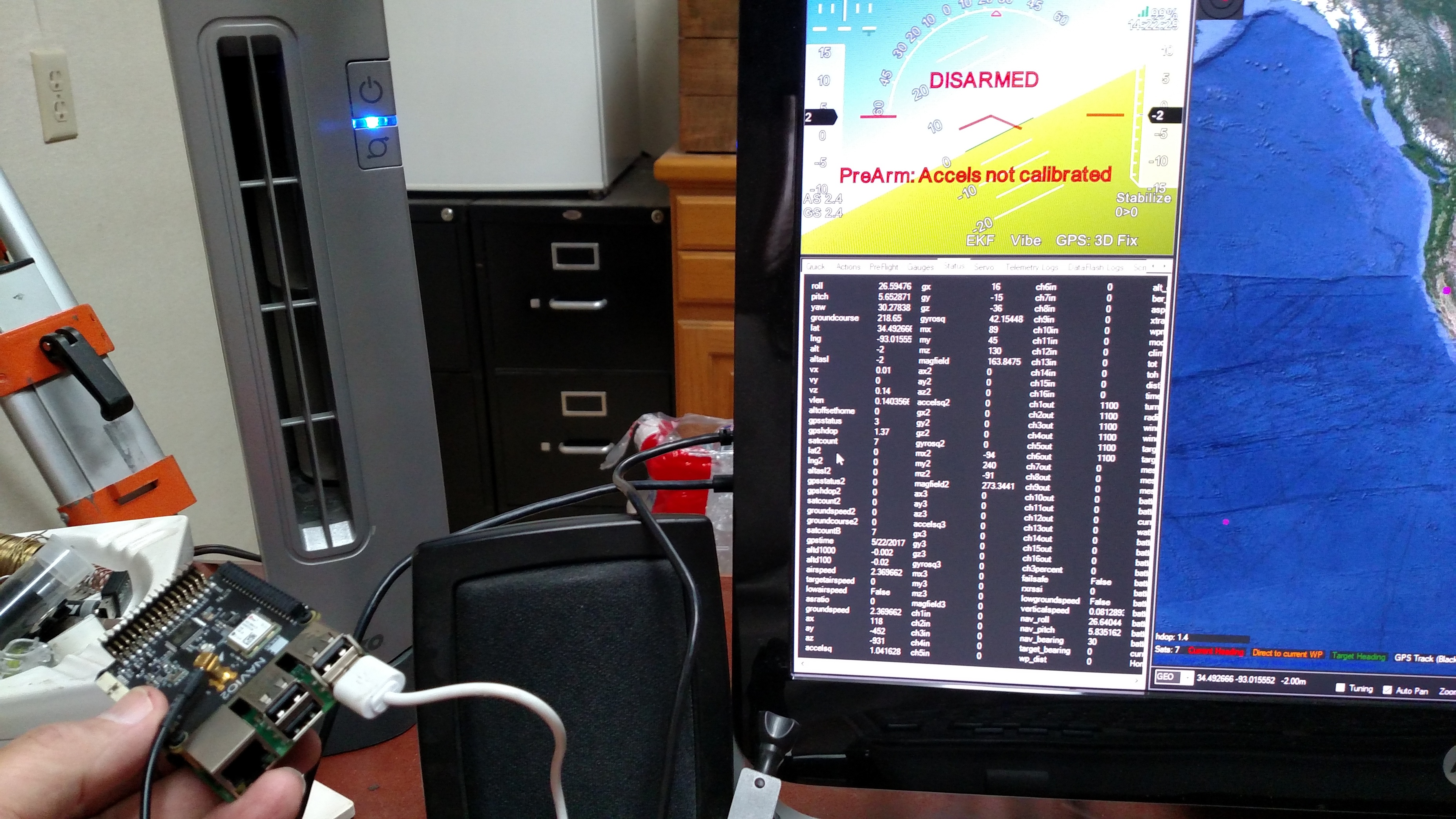
Hook up the radios to Navio2, hook reach up to navio2 and use mission planner to inject correction into reach from base.

I also need to allow for camera and camera gimbal control, FPV 9or at least video from camera), as well as telemetry back to my Radiolink AT10.

I’m not looking for connection to my computer in the field at this point. (I don’t think)

I love the flexibility of the Navio2 and Raspberry Pi, but without a diagram showing “best use practices” for hooking up the peripherals, I’m envious of PixHawk and It’s labeled inputs on the box.

Do you have an overall schematic you would recommend?
What typically in hooked up via l2R and ADC connections?
On the reach unit, there appears to be 2 DF13 connections, are they the same? could they both be used at the same time?

Thanks in advance, in the meantime I will revisit (for what seems like the 100th time) the link you posted.

Still working through the commands.

1 no problem on reach settings, double checked and I understand the goal.
2 no problem setting up incoming corrections from base in mission planner


3 one problem setting up radios, I don’t know if I did this

To change radio settings, make sure Mavlink connection is disabled.

Where do I do this, on the reach, on the navio2, inside Mission Planner?
Regardless. I think it worked:

Do I still connect Mission planner to the Navio2 with UDP, like before or do I need to change the start up command to reflect Com 3, (That’s where windows device manager shows my radio to be connected.)
Ardupilot auto starts on boot for me, do I edit the commands in the /etc/default/arducopter file? if so what is TELEM1? TELEM2, do i just add TELEM3 or is that supposed to be GPS2?

As it is now,
TELEM1=“UDP:##.##.##.###:14550
TELEM2=”-C /dev/ttyAMA0"
TELEM3=“-E /dev/ttyAMA0”

ARDUPILOT_OPTS=“$TELEM1 $TELEM2 $TELEM3”

Thanks!

Hello.
From picture “RTK/GPS inject” I can see that vehicle isn’t connected to Mission Planner. You need to disconnect vehicle from MP only during the radio setup. For normal working of GPS inject connection is required.
Has gpsstatus2 changed from 0 after setup in MP?

The diagrams in the Emlid docs are all I have used in the past.

I2C is typically external sensors like magnetometers, LIDARS, etc. You do not need I2C for your 2nd Reach as it uses Serial. I2C is sensitve to noise and not a good first choice for a wired connection. I am forced to use it for an external mag. Can’t wait until all this stuff is CAN enabled but that is a subject for another thread.

ADC is used for external sensors that use analog such as voltage and current sense. Some LIDARS will output analog. It’s a voltage level that varies and is converted to some specific digital meaning (0’s and 1’s); thus analog to digital conversion (ADC). Also sensitive to noise; especially at the low voltage levels we use across the wire.

The two connectors on the Reach are not functionally identical. The one next to the USB is meant for your primary serial and power connections to things like PixHak/Navio. The other has different pin out, which includes an event trigger pin that we use to synch shutter event to time stamp in Reach logs for PPK.

Pinouts are here:

As for the rest:

I would try to keep it simple and hook it up per the Emlid docs. Don’t try to add NTRIP or other outside source of complexity until you know the base system is working as it should.

Here’s the hard part: Navio only has one serial port. If you use a 3DR Radio for telemetry you will need to use a USB to serial adapter (hmm, perhaps this can be direct USB connect; have not used a 3DR radio in years) for the 3DR radio so you can plug your Reach into the serial port on Navio. Then your telemetry switch becomes
-C /dev/ttyUSB0
-E /dev/ttyAMA0

Perhaps the easiest way to start with an RPi3 is to use the built in Wifi for telemetry testing (we use an external dongle for range but that is more complexity not needed for bench testing).

Then you just need:
TELEM1=“UDP:##.##.##.###:14550
TELEM2=”-E /dev/ttyAMA0"

And…

  1. Base is connected to the same WLAN as your GCS laptop
  2. Your laptop is connected to said WLAN, and if you are running Windows, the WLAN is set as a Private network with the firewall turned off. And don’t assume this setting is sticky. Windows is very helpful.
  3. Your Navio/Rpi is connected to same WLAN via WiFi
  4. Mission Planner receives RTCM via TCP from the Base on the LAN
  5. Mission Planner Injects via UDP on your WLAN WiFi connection to the copter

As long as you follow the steps this should work. Once it does you can start adding/changing your comm plan one step at a time.

And you will need to be outdoors or the Base and Rover Reaches will likely not finish booting due to no time sync. And even if they do I have seen gps2status stay at 0 unless the reach rover is outdoors.

Yes, lots of pieces to the puzzle. That is why I recommend a base system with as few connections as possible in order to test and gain knowledge of the system. Then work from there.

Thank you @coby for the response.[quote=“coby, post:6, topic:6082”]
I would try to keep it simple and hook it up per the Emlid docs. Don’t try to add NTRIP or other outside source of complexity until you know the base system is working as it should.
[/quote]

I’m very comfortable with RTK through TCP. 3DR Radio and NTRIP. I’ve been using many combinations of TCP, Radios and the internet for months with great success. I don’t feel connections from Mission Planner to the Reach I’m using as a Base are not a problem. If I can get [quote=“alexey.bulatov, post:5, topic:6082”]
Has gpsstatus2 changed from 0 after setup in MP?
[/quote]

to happen and still can’t get corrections to the rover, I’ll make that my focus.

I’m 90% sure this is where my problem lies:[quote=“coby, post:6, topic:6082”]
Here’s the hard part: Navio only has one serial port. If you use a 3DR Radio for telemetry you will need to use a USB to serial adapter (hmm, perhaps this can be direct USB connect; have not used a 3DR radio in years) for the 3DR radio so you can plug your Reach into the serial port on Navio. Then your telemetry switch becomes
-C /dev/ttyUSB0
-E /dev/ttyAMA0
[/quote]

When ssh into the navio/raspberry, and type “-C /dev/ttyUSB0” the response from Pi is -bash -C: command not found. This is where I’m pulling my hair out.

I’ve been editing my Arducopter config file to make the changes. I don’t understand, you said [quote=“coby, post:6, topic:6082”]
-C /dev/ttyUSB0
-E /dev/ttyAMA0
[/quote]

What do i do with that info? then you said [quote=“coby, post:6, topic:6082”]
Then you just need:
TELEM1=“UDP:##.##.##.###:14550
TELEM2=”-E /dev/ttyAMA0"
[/quote]
which doesn’t even mention “-C /dev/ttyUSB0”. Where do I assign or “Turn on” -C?

My radios are connected to my desktop and Raspberry Pi using USB, Mission planner will load info per the instructions.

Both my units boot indoors no problem and I can get corrections indoors, Obviously not enough GPS to achieve any type of solution (Single, Float and definitely not FIX)

I will move outdoors and see if the gps2status changes.

Thank you for your help!

Both Base and Rover/Navio/Pi units are outside, and have been up for 10 minutes. no gps2status

Ok everybody, forget RTK for now. I need to connect my reach to my Navio2. At the least @emlid could you post a link to the most current workflow and I’ll start over from there, I’ve been working through the old posts for since Friday and the last time Ended up on a thread from 2015. Please?

Could you please post photo of you setups (how reach connected to navio2), settings of Reach and Mission Planner (GPS-TYPE2, SERIAL4_BAUD, GPS_INJECT_TO) and also file /etc/default/arducopter?
ArduPilot integration docs were updated yesterday.

1 Like

Mike,
If you get rid of the 3DR radios for now you do not need the -C switch. I have no doubt you know what you are doing with GNSS. Far more than I do. SNIP is on my list to learn. Have it installed and only tried it once. But I have been building and troubleshooting different complex systems for decades and have learned that you must start simple and establish a base system first; then build out one step at a time. Especially when you have multiple external dependencies with hardware and software from different open source projects.

You can’t run those from the command line. When you ssh into Navio all the help should be coming up in the console.

Just follow the prompts, which are also listed here: https://docs.emlid.com/navio2/common/ardupilot/installation-and-running/

If you run just WiFi like I suggested you do not need the -C switch as it is normally reserved for a telemetry radio such as the 3DR. Here is one of my copters for an example:

TELEM1="-A udp:192.168.x.x:14550"  <- That is my WLAN setup for UDP
TELEM2="-E /dev/ttyAMA0" <- That is my Reach Rover on the UART/serial port 4
TELEM3="-F /dev/ttyUSB0" <- That is my LIDAR on a USB to serial adapter on serial 5
# Options to pass to ArduPilot
ARDUPILOT_OPTS="$TELEM1 $TELEM2 $TELEM3"

The -A, -E and -F just represent a port. You are essentially using command line options to setup a router. You are telling the system how everything is hooked up so it knows where to send/receive data.

Mapping between switches and serial ports (TCP or UDP can be used instead of serial ports):

-A - serial 0 (always console; default baud rate 115200)
-C - serial 1 (normally telemetry 1; default baud rate 57600)
3DR Radios are configured for 57600 by default, so the simplest way to connect over them is to run with -C option.
-D - serial 2 (normally telemetry 2; default baud rate 57600)
-B - serial 3 (normally 1st GPS; default baud rate 38400)
-E - serial 4 (normally 2st GPS; default baud rate 38400)
-F - serial 5

Once you have that done you can inject via Mission Planner. Doublecheck all the parameters in ArduPilot via Mission Planner Full Parameter List. Use the search bar on the right to save a ton of time. Search “gps” and check all params. Then search “serial” and check all the params. If I have a system not working it is usually in there.

If that does not work then we may have to revert you back to an older Mission Planner to have parity between ArduCopter 3.4. Much has changed with GNSS handling in ArduCopter 3.5+ and the newer Mission Planners are written for it, which does not help us right now. Also, most of the ArduPilot community testing is happening with UBlox M8P units, so that does not help much either. Like I said, much churn.

This is the last thing I saw from Emlid on Mission Planner versions (on another post around here somewhere)

Version 1.3.43 is required for ArduCopter 3.4.6

Hope that helps.

1 Like

Just a quick question, Is “-E /dev/ttyAMA0” universal, it doesn’t seem to work fro me. I found a thread somewhere (I can’t find it again:rage:) with a command I ran before and after plugging in the reach unit. I then compared the output produced by the command, the /dev/ttyAMA0 showed both times, something like /dev/ttyAMC0 was there after I ran the command with the reach p[lugged into the uart port on the navio2.

Again my questions is this.

Is “-E /dev/ttyAMA0” universal? Thanks

Thank you @alexey.bulatov, I’ll test and upload ASAP

It’s very user friendly, It was my first experience and went off without a hitch. My only disappointment was discovering that the “Lite” version. While it is full function and free, it only works for 1 hour, then it must be restarted. This works great for testing, but we’ll be looking at the $495 version once we get up and running. For the price vs ease of use and functionality, I still think it’s a bargain.

/dev/ttyAMA0 is the uart port for Navio.

The letter you use is the serial port assignment ardupilot will expect to use. That is the router part. You are mapping an ardupilot serial port to a linux serial port. -E is serial4 in ardupilot and AMA0 is the linux port.

Also suggest you read the comments in full parameter list in mission planner. It will give you an idea of what your options are on the serial ports. -C is ardupilot serial1 which defaults to radio telemtry. So even though navio has only one uart you can map it to serial1 thru serial5. You can then set the protocol and baud rate to support telemtry, gps, or sensors such as lidar vIa the parameters for the respective serial port.

1 Like

I will re visit this, hopefully it will make more sense after reading your posts, thank you

Make sure you are connected to the robot in mission planner or your parameters will not load. You also need to switxh to “advanced” in mission planner. Go to config/tuning -> Planner -> layout (?) -> advanced. It may say basic. On my phone so best guess.

1 Like

Reach connected to Navio and computer. Mission Planner is connected on the Windows machine on the right, SSH into Navio2/RPi on linux laptop on left
:


Base connected to internet providing correction via NTRIP (inside so obvious no fix)

Radio Set Up:

Reach settings on Rover both correction in and position out:

Mission Planner Settings to rover:

File /etc/default/arducopter:

EXTRA Images:

Mission PlannerGPS Inject:

:sweat_smile:

So I can see that settings of MP and ReachView are right.
But in file /etc/default/arducopter the string TELEM2="-c /dev/ttyUSB0" is wrong, because parameter should be upper case. It’s strange because ardupilot can’t start with unknown option.
You can test with another way:
stop arducopter using command: sudo systemctl stop arducopter and after try:
sudo arducopter -A udp:10.0.1.14:14550 -E /dev/ttyAMA0 and after connection to Mission Planner check value of gpsstatus2. It should change from zero.

1 Like