Hi, I want to read out the IMU values like gyro, accel and magnetometer. For a certain time it works, but then I get only 0 for the magnetometer and only a restart of the Reach RTK fixed that issue and I get back normal magnetometer values. Is there a possibility to fix that without an restart or does someone know what’s the problem?
Quite possible that there is some issue with the driver, but this is not officially supported yet. We will get to it and everything will work just fine
Is there any update on supporting magnetometer? I have the same issue, that sometimes I get all 0 values. It happens in 5% cases. When I restart initialize the MPUtest again, then I get the readings.
My main question is, can magnetometer be used to find out the heading (yaw)? As it seems to me, if I turn the module on ground, the magnetometer readings do not change much. Should I read something in addition?
If the IUM will be tilted by any significant amount you will also need to use the accelerator data to compensate for tilt.
I did experience the magnetometer returning zero values when I first started playing around with it but I haven’t experienced it for a long time. Form memory, I think I fixed this problem by running the magnetometer self-test and only starting the data feed after it passed the test (sometimes it takes multiple attempts). But I could be wrong here, it has been a while since I looked at the code.
I checked your links and this seems promising. I have however a question. The raw magnetic data coming from the module seems quite static when changing the heading (yaw). When turning the model around in other directions, the magnetic values change. Is this normal? I cannot see a way how a correct heading can be calculated based on those “static” values. By “static” I mean they change a bit, but in general they stay in the same range (+/- 10 or so, depending how smooth I can turn the module).
Am I missing something here?
Just a small example, I made the full turn with the module. That’s what MPUtest gives me:
Those are just some lines. But as you can see, the mag part is basically the same (all those remain in the range 15 … 26 or so).
Am I missing something?
Hi @ago, I had the same thought when I first started testing the magnetometer. But there are a few factors at play here.
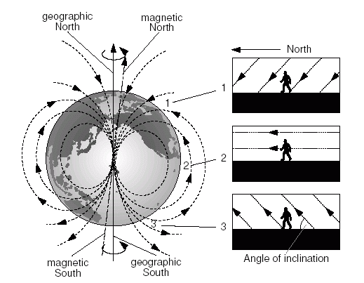
Inclination - Where I’m located (Ballarat, Australia) the magnetic inclination is about 68°. This means that there is only a small component of the total magnetic filed in the horizontal plane.
Hard-iron distortion - In my case, the magnetic distortion, due to hard-iron effects, was so great that it shifted the entire field into the positive (or negative) range.
By performing a hard-iron calibration you will shift the field into the center (you will get both positive and negative values). By performing a soft-iron calibration the magnetic field will be scaled equally in all directions.
After performing the above calibrations, the small magnetic field present in the horizontal plane will work as expected.
I understand the idea behind the calibration. I have tried several different tools to calibrate the magnetometer. But still no luck. So, I have the following questions:
Did you get it working with Emlid Reach RTK kit?
What software did you use to read data from IMU and magnetometer?
What software did you use to do the calibration?
How did you apply the calibration data? Like, did you change the software you use to read data? Or do you apply it later on somehow?
Is there a difference how the module is placed on the moving device? Like, should the forward moving direction be x-axis and z points up? Or something else?
Some soft try to do calibration themselves. All my tries end up with the result where the magnetometer doesn’t recognize any change in yaw. This is tested so that z points up. I apply the calibration after the magnetometer readings. So, from the module itself, I still get the same data, but use calibrated values to normalize the result.
I have tried two modules. One was inside a metal construction, the other was plain module with not significant metal near-by. Both have the same result - no change in yaw when rotating.
The raw calibrated data is send from Reach RS, calibration in applied in my application.
It is important that you use a consistent convention with the accelerator, magnetometer and Reach RS. From memory the magnetometer and accelerator do not have the same orientation and both were different to the orientation that made sense for my application so I ended up transforming both axes to match the desired orientation for Reach RS.
If after this you still can’t get it working please PM me and we can set up a time to have a chat about it.