


So I’m trying to feed location data via UART/NMEA to an INS module. When I connect it to the INS I get nothing. So I purchased a USB to TTL adapter (https://www.amazon.com/gp/product/B075N82CDL/ref=ppx_yo_dt_b_asin_title_o01_s00?ie=UTF8&psc=1), determined the COM port from the device manager and opened Putty to try and see if the M2 was sending NMEA messages. When I connect, I don’t see anything. Am I doing something wrong? I connected the TX wire from S1 to the RXD on the USB adapter.
SystemReport M2.zip (526.6 KB) SystemReport M2.zip (526.6 KB)
Did you give the converter 5v from the red wire on S1? Do you have the ground connected?
I know its a bummer but S2 is reserved for Lora… I wish it also could be a ttl port.
Does your computer accept the device in “Device Manager”?
Caution only plug the red wire in with the M2 usb power removed, just in case. You can input power or export power in one direction only or … pop goes the M2
Converter, being usb, got power from the computer. Is that what you mean?
Yes, device creates COM7 in the device manager.
Ok do you have a multimeter? Measure vcc pin on converter to make sure its powered.
Have you tried swapping tx rx?
Have you set up your comport settings in device manager?
Have you setup your serial terminal software to make sure its through your computers firewall (Windows is super horrible when it comes to blocking stuff)
Try “NMEA router”, its free and I found its a great data debugger cause it will literally dump anything coming out the serial port up in the screen. Too bad the old dude who coded it passed before it was fully finished its quite excellent.
Ok the power thing is worth its own post.
The m2 can be powered from the usb port or the JST red wire but not both, because power will flow through it on a common bus. But if you power both the JST red and the Usb you from separate power supplies that are at different ground potential then “pop” 10v plus fries the m2.
But this is handy cause you can run auxiliary equipment through the m2 with only one power supply.
Most 232 converters require outside power as ttl is a t 3-5v, and 232 is hovering around 12v DC so the 5v on the converter vcc pin is used is used to up convert the voltage of the applied ttl signal so a 232 terminal can use it.
You are almost there, protocol conversion is only difficult to keep quitters out lol.
I just recently converted ttl to 232 to 422 then back to 232 and it now cuts my grass, you just have to keep trying. But it is truly infuriating sometimes.
1 Like
Ok, I’ll check this.
Ok do you have a multimeter? Measure vcc pin on converter to make sure its powered.
Yes
Have you tried swapping tx rx?
Can you explain this a bit?
Have you set up your comport settings in device manager?
I’ll check.
Have you setup your serial terminal software to make sure its through your computers firewall (Windows is super horrible when it comes to blocking stuff)
Thanks
In device manager you will see your device and assigned COM port number.
Right click properties, should show properties, enter properties.
Most programs will set the settings for baud regardless of whats here. But set them to 38400,8,None,1 this is most common settings for debugging GPS NMEA sentences. If the baud rate is too low with too much data problems, if the baud rate is too high and the converter cant keep up problems.
Ensure the settings in emlid, device manager, and serial program match.
Click the advanced button in device manager settings. This page is specific to hardware i am unsure what you will see here. But if it describes fifo buffers turn both sliders down to 1/3. If that does not work try with them off.
1 Like
I’ll take a look. Thanks!
So i see solution, so i take it that its working?
So trying the nmea router did nothing. This is what the screen looks like.
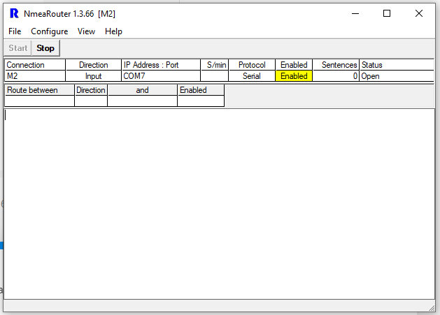
Setting the port settings via properties and it also did not produce any messages. Ive tried two different M2’s with no luck.
Let me ask this. I checked the VCC and Ground. It showed a negative -5.05 volts. When I reversed them, POS on GND and NEG of VCC, it showed a positive 5.05 volts. When I connect the M2 to the USB VCC and GND, it shows the orange light but it never fully turns on. So then I connect an external 5V lipo via down converter to get power. Does the USB and M2 need to be connected through the VCC and GND? I recall someone mentioning that TTL needed to be connected to the same ground to work?
I looked again at the amazon pinout page
I would only have black to ground, purple and white to tx and rx ( or try reversed tx and rx reversed)
Leave the red wire off
Power the M2 off its own supply
Put your switch to 3V level for the ttl
Also if you are trying this inside the module will not output anything till its at least in float.
Ensure nmea router is in stop when you change settings for them to stick.
1 Like
So the common ground was the issue. It started spitting out everything. Thank you so much!
1 Like
No problem! now you have the power of protocol conversion.
I think you will really like NMEA router, it has saved me a pile of time testing and tinkering.
It will also show rtcm3 as a jumbled mess, but at least you know its coming out.
Another great free tool for gps is RTKlib.
Its frustrating sometimes, but i bet it feels great now that you have solved the puzzle.
Next step is to see how far you can tinker till it breaks again lol! 
Very true. I’m working on a new harness to the INS. Once this is solved, I am ready to start flying this new LiDAR kit. Thanks again. You have saved many hours of sleeplessness.
1 Like
This topic was automatically closed 100 days after the last reply. New replies are no longer allowed.