How do Camera events differ from Stop and Go survey on processing side

I am just now getting into PPK on my Phantom 4 Pro using the kit I got from @Brian_Christal at TuffWing. He has a very nice step by step on processing the Reach RTK or Reach M+ using RTKlib.

So looking at this from a processing point of view, how does processing the Camera Events that are triggered on the M+ drone flight differ from processing a stop and go survey on the ground??

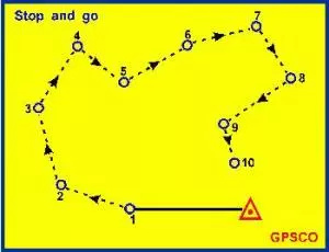
Using the Reach M+ o the ground would be much more difficult due to signal strength, at least that is what I found with the Reach RTK original. But when the unit is in the air 200-300’ agl then it is a none issue. The Reach RS does not have the option of Camera Events but I am just thinking outside the box. It seems to me that the Reach M+ is a Stop and Go survey in the sky (hmmm. maybe just a “go survey” since there is no stopping!)

So why can’t ground surveys be processed exactly the same way that drone flights are processed using the Reach M+ module?

If the Reach Rs supported camera events, could a camera not be put on a pole and take a picture to trigger the survey point (sort of like @TB_RTK mounted the camera to view the bottom point of his latest dual head super cool setup!). And actually, my question is not so much about using a camera to create an event (not sure how practical that would be anyway) but more about why is processing a stop and go survey in RTKLib not the same as processing a drone flight using the M+? (or is it)

Thanks for any thoughts and insight

I want to ask this in a different way to better explain my thinking and hopefully my question will make better sense. In my simple way of thinking, when you use the M+ on a drone and the drone triggers a “Camera Event” on the M+ each time a photo is taken, what is truly happening is a point on earth is being surveyed, but instead of being on a 2 meter pole it is, say 100-400’ above ground.

Now I can follow a simple guide to process that data (camera events) using RTKLib and in fairly short order I will have the precise coordinates for each photo that was taken. This is with the assumption that I am using a base station for corrections and the coordinates of the base station are known.

That is a very simplified overview because there are timing issues due to the drone moving, camera tilt, etc. But in a general view, this is a survey taken in the air.

So now I move the survey to the ground. If I had a clear sky and the M+ had good satellite reception on the ground, I I could walk around with the M+ mounted on a survey pole, along with a camera. I could then place the survey pole over GCP markers as usual, then take a picture of the GCP to trigger the camera event on the M+. The event is now logged and will be tied to that photo. I walk to the remaining GCP’s and do the same thing.

Now I follow the same process as I did with the drone photos/camera events, except this new set was done with the M+ mounted on survey pole. Can this be done with accuracy, yes or no? And in this scenario, there is no movement, the pole is stationary, perfectly level over the point being surveyed.

If it can’t be done, why not?
If it can be done, then why can’t this same principle be used with the Reach RS?
If it can be done on the Reach RS, how does the process differ for the RS vs the M+ with camera events?

Here is the very well described process for the processing the M+ by Brian.
Step 1: Tuffwing: Simple Reach PPK Tutorial
Step 2: Reach Setup for PPK Processing on a UAV

I hope this second version more clearly states what I am trying to learn.

Camera event is one single epoch designed to be highly accurate (precise might be a better word.) as its target to create timestamps exactly when an event has happend in millisecond, thus put a timestamp on that single epoch. You also dont get RMS value from the collected itteration e.g 10-20 . Meaning you put all your faith into one with the timestamp on.

The true stop&go solves its true position based on multiple epoch and has many other ways to resolves ambiguities like quoted below

This is the kinematic technique because the user’s receiver continues to track satellites while it is in motion. It is known as stop-and-go (or semi-kinematic) technique because the coordinates of the receiver are only of interest when it is stationary (the stop part) but the receiver continues to function while is being moved (the `go’ part) from one stationary set up to the next. There are in fact three stages to the operation.

The initial ambiguity resolution: carried out before the stop-and-go survey commences. The determination of the ambiguities by the software can be carried out using any method, but in general it is one of the following:

A conventional static (or rapid-static) GPS surveys determine the baseline from the reference station receiver to the first of the points occupied by the user’s receiver. An ambiguity-fixed solution provides an estimate of the integer values of the ambiguities that are then used in subsequent positioning.
Set up both receivers over a known baseline, usually surveyed previously by GPS, and derive the values of ambiguities in this way.
Employ a procedure known as antenna swap. Two tripods are set up a few metres apart, each with an antenna on them (the exact baseline length need not be known). Each receiver collects data for a few minutes (tracking the same satellite). The antennas are then carefully lifted from tripods and swapped, that is, the receiver one antenna is placed where the receiver two antennas had been, and vice versa. After a few more minutes the antennas are swapped again. The software is able to resolve the ambiguities over this very short distance.
The most versatile technique is to resolve the ambiguities on-the-fly (OTF) (that is, while the receiver is tracking satellites but the receiver / antenna is moving).
The receiver in motion: Once the ambiguities have been resolved the survey can begin. The user’s receiver is moved from point to point, collecting just a minute or so of data. It is vital that the antenna continues to track the satellites. In this way the resolved ambiguities are valid for all future phase observations, in effect converting all carrier phase data to unambiguous carrier-range data (by applying the integer ambiguities as data corrections). As soon as the signals are disrupted (causing a cycle slip) the ambiguities have to be reinitialized (or recomputed). Bringing the receiver to the last surveyed point and re-determining the ambiguities can most easily be done using the known baseline method.
The stationary receiver: the `carrier-range’ data is then processed in the double differenced mode to determine the coordinates of user receiver relative to the static reference receiver. The trajectory of the antenna is not of interest, only the stationary points which are visited by the receiver.
The technique is well suited when many points close together have to be surveyed, and the terrain poses no problems in terms of signal disruption. The accuracy attainable is about the same as for rapid-static technique. The software has to sort out the recorded data for different point and to differentiate the kinematic or go data (not of interest) from the static or stop data (of interest). The technique can also be implemented in real time if a communication link is provided to transmit the data from the reference receiver to roving receiver.
image
One negative characteristic of this technique is the requirement that signal lock must be maintained as the satellites by the user receiver as it moves from point to point. This may require special antenna mounts on vehicles if the survey is carried out over a large area.

Hey Tore, thank you for the reply! I checked and I was able to receive 1 hour of continuing education credit for reading that :stuck_out_tongue_winking_eye:
As I continue to learn this stuff I just like to know the how and why’s. After reading your reply I am still left with the question of why is capturing a single epoch during a drone flight considered precise and yet that same technique can not be used on the ground? Obviously when flying a drone you have no choice but to use a single epoch because the drone is in motion. Maybe the simple answer is that when flying a drone, capturing a single epoch is the only option, and while using a single epoch is precise given the circumstances of movement, it is impossible to match the accuracy of resolving multiple epochs as used in a ground survey.

When I get my M+ in I will do a test similar to what Christian did but with the M+ to compare a survey using ReachView app to camera events capture. I will have some fixed bases setup so that the physical position does not change when the unit is removed and placed back on it. It will be interesting to see the results.

If using Camera Events would yield a 5cm accuracy (or whatever level) and it can be easily processed in RTKLib (where apparently Stop and Go can not be done easily in RTKLib), would it not be the desired method if the provided accuracy level is acceptable?

It may be worth Emlid allowing for a “single epoch survey” in the Reach RS/+ units which would emulate a Camera Events data collection on the M+ which would then allow for a very quick and easy processing in RTKLib. Ya’ll may think these are stupid questions but you do not learn if you do not ask.

I have read the piece before about doing the antenna swap. Does anyone do that with the Reach RS units?

Thanks again for the insight!

The understanding of accuracy in terms of data produced by a moving plane and a static pole on the ground is different i would think.
They speak of cm accuracy in drone mapping, but I believe its more sub 5cm in most cases, maybe 10cm. Their data it all teoretical and really hard to verify without resurvey the entire area on the ground. Theory and practice doesnt always go hand in hand.
So, for usage of a single epoch, even if its not entirely right, in terms of cm or even 5-10 cm in the air, its still a decent and good accuracy for an airborn moving measurement.
On the ground that would be bad. On the ground we would have more control over the movement, thus demand for higher accuracy but also data to verify or to tell if the green dot is right or not.
That’s why e.g RootMeanSquare is used as term to establish level of error on a given reading and that can not be done with a single “poch” or in a camera event.
Sure, its doable to use camera event or any other similar workaround to get you in the ballpark or even very close to true position, but to get the propper stop&go working and accurate reading when the pole is static you need more time.

An example of that is to try measure a point with sub cm. If you look at the plot, you see it fluctuate and if you grab one of those dots how do you know how accurate that reading is? and at what probability that dot is accurately measured?

Well thats how I understand it, hope its within 86% RMS, I made enough bold statements for the rest of the year :smiley: .

1 Like

Guess i am not the only one with bold statements :laughing:
Lets see if this solution still stands in 48 hours… :thinking:

ah now, I believe this one has a nail in the ground. here to stay :smile: I will play around with some tests just to see how stuff compares. Take care TB!

This topic was automatically closed 100 days after the last reply. New replies are no longer allowed.

Hi there,

If you stumbled upon this old topic, I just wanted to let you know that now you can work with Reach receivers using Stop & Go with the help of Emlid Studio. You only need the raw data from a rover and a base and the CSV file from ReachView 3 with the collected points. For more details about this functionality, please check our comprehensive guide.

In case of any questions, feel free to create a new topic!

1 Like

2 posts were split to a new topic: How to work with Stop & Go