Hello folks,
we are currently testing the accuracy of the Emlid products we use for our UAV surveys and reference data collection.
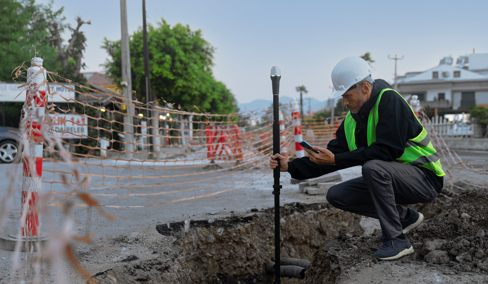
In one of the tests we mounted a RS2+ unit on a 2.1 meter carbon survey pole wit attached bipod to keep it stable during point measurements. The total distance from the antenna is reported as 2.234m (Adjusting for the Antenna of the RS2+)
The carbon pole has a bubble level with an accuracy of 40’. If we do the math: sin((40/60)°) * 2.234m = 26mm. So we could have an lateral error of 26mm in our measurement which is not neglibile.
Now we could order a more precise bubble level or get a smaller pole to reduce this error. However i was wondering whether we actually need to be that precise or if the Emlid reach units already account for this.
We set the pole length in Emlid Reach and the units have an IMU which can measure the level.
Do the Emlied Reach units correct for off-level placement ? And if yes do we need be accurate with leveling at all? If we can just eyeball the pole to be approximately level this can speed up point acquisition a lot.
According to this discussion the Emlid units don’t include tilt into the calculation of the surveyed point. That means we will add some error by off nadir.
In the marketing materials it looks like this is not an issue and measuring points without a bipod is possible. In construction it’s the resulting accuracy might be sufficient though?
Emlid offers also a survey pole for the RS2+ unit. What is the accuracy of the bubble level?
The best bubble level I cloud find has 10’ (arcminutes) accuracy (6mm lateral error @ 2.234m). Does it make sense to use very short pole even if it means the the antenna has a less optimal position?
2.6cm isn’t good? Who makes a 2.1m pole? Just so I can make sure I never accidentally buy one. We use 40’ vials all the time and hit within our 0.10ft tolerance easily every time. If you need more accuracy you need a robot.
Small hint : if you use a bipod during measurements, you can record the point twice by rotating the pole 180° between both takes and this way, the average cancels the plane error.
It would just help XY. Z wouldn’t/shouldn’t be affected by rotating 180. I am seeing better than a tenth vertically whether using VRS, caster, or lora if baselines aren’t too long.
I agree with Michael, if you’re looking for more accuracy you would need a robot.
But here are some other possible solutions to gain more accurate placement of your GNSS receiver.
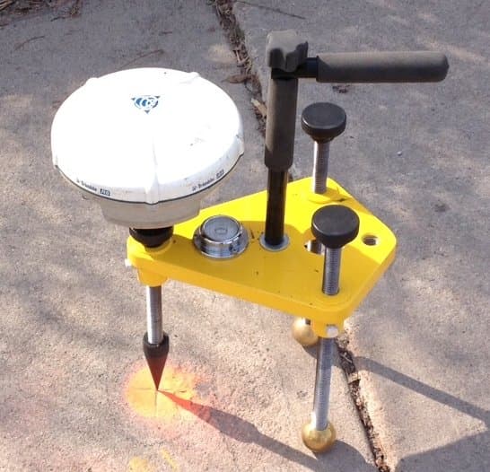
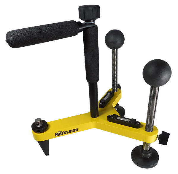
The Marksman
Typically used with prisms, though I seen it demonstrated using it with GNSS Receivers. Pictured with no extension pole, but I seen examples with various size poles for placing the receiver higher.
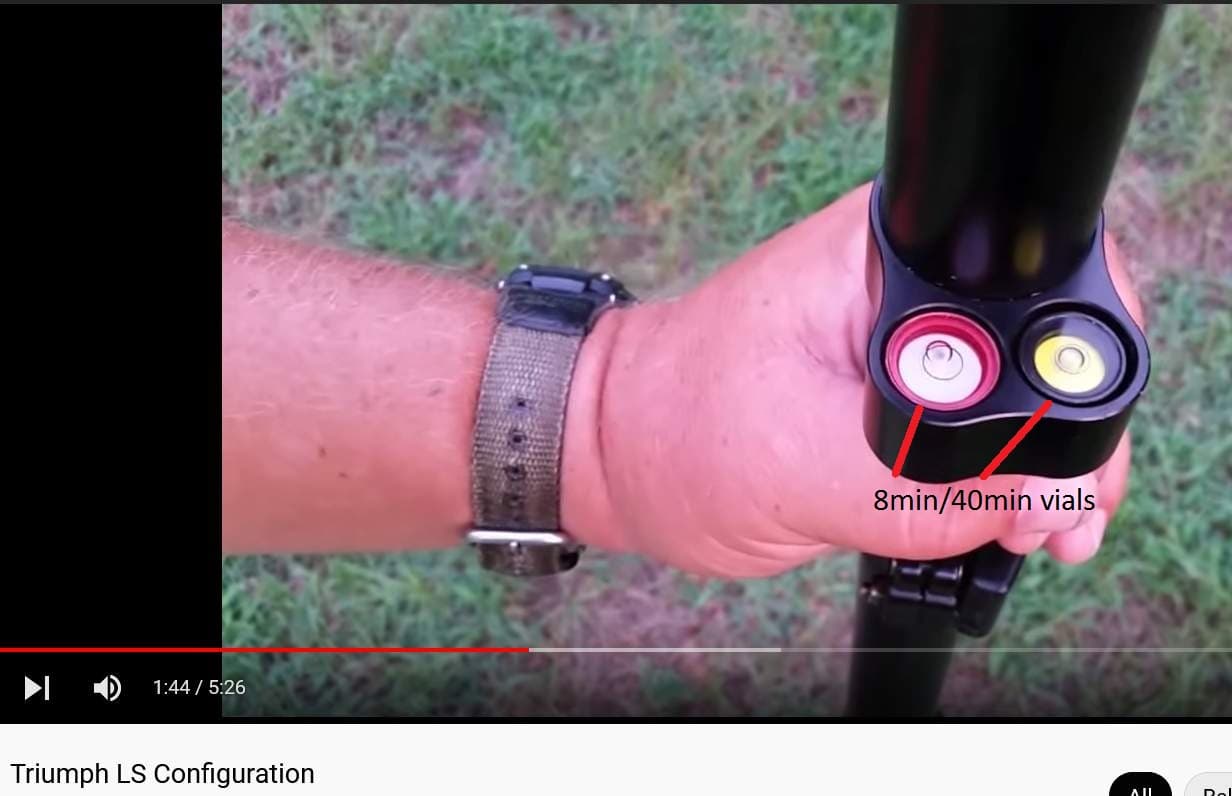
Or Javad makes a collapsible Monopod for their units that includes a dual 8min/40min bubble vial. Only thing is that it uses a 1/4-20 thread, so you would need an adapter to fit the RS2 5/8 thread. They also sell the double vial by itself.
In practice, this is less, if you make it habit to always have the bubble in the very center of the circle.
Remember that including an IMU in these calculations also introduces yet another error-source, that contributes with its own error budget. So mechanical levelling is to be preferred, if possible.
First of all thanks for all the good ideas! I would like to add some more details to the discussion:
We tested the Reach on a official test site that is used for checking survey equipment before it is allowed to be used for land registry work in Germany. The GNSS Rover must be capable of a horizontal accuracy of <15mm. Accuracy is measured by observing 5 reference points in two independent surveys with at least 15 minute pause in between. The points from the two surveys are averaged before calculating accuracy. Given the sources of error: GNSS Error(optimal cond. 7mm) + Pole tilt( 26mm) reducing the possible pole tilt error is something I can more easily control.
Here you go if you want to never accidentally buy one. The brand is Geo Fennel. Though, its two meters in length and we used a 10cm extension to have a similar height to compare it to our setup with a Reach M+ receiver. But honestly: Is that too tall? I met other surveyors (employed by the state) on the site with poles of similar height.
Agreed, I adopted that habit too. However, I recently gave two students an introduction into surveying points. We got into a discussion about how much level is enough. Which showed me that it is hard to meet an accuracy target if it is not clearly defined by the black line.
Really interesting equipment you linked in the post, I agree manual levelling especially with the long pole has it’s limits in accuracy. That’s why I was hoping there is a way the Emlid GNSS geared towards surveying (e.g. RS2) account for that.
And thinking about it more I start to see why it was probably not done: For the tilt compensation to work properly without calibrating on-site you need two very accurate IMUs, one at the top and one e.g. in the middle of the pole (i.e. spaced far apart). Their exact position relative to each other must be determined. Then by solving for the gravitational normals of those IMUs it should be possible to determine the off-level XY angles and calculate the XY offset of the point. Based on the costs for the IMUs we use for LIDAR post-processing this could increase the cost of a Emlid receiver easily by 2x - 5x depending on how accurate it should get. And because Emlid products were originally design with UAV RTK positioning in mind its just not worth the additional cost?
I haven’t worked with RTK receivers of other brands that are in oftentimes in the 5x-10x price range compared to Emlid receivers. Has someone worked with those and can confirm that they use automatic tilt compensation? Because this is the only way It would explain why the other surveyors I met on the site where using long poles without any special procedures and still hit the desired accuracy targets of <15mm.
Results of a first test:
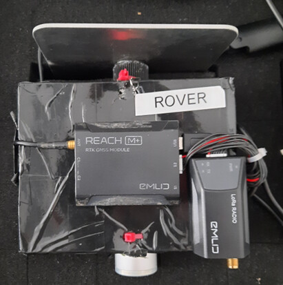
SAPOS(German NTRIP Caster Network) + Emlid RS2 + 2.1m Pole w. Bipod → 1.95cm RMSE
SAPOS + Emlid RS2(Base) + Emlid M+ (Rover) + 2.1m Pole w. Bipod → 4cm RMSE
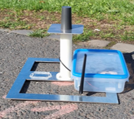
SAPOS + Emlid RS2(Base) + Emlid M2 (Rover) + Metal Square with 3D printed standoff (image below) → 1.5cm RMSE
The M2 was more accurate on a small stand off compared to the other setups even without being level. Rather than spending thousands on tilt compensation the best approach is to use the shortest pole possible with a vial that supports the accuracy target.
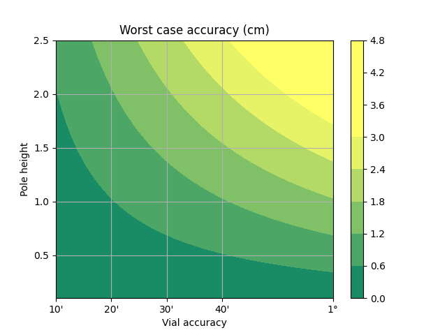
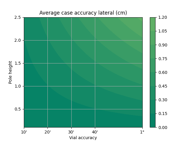
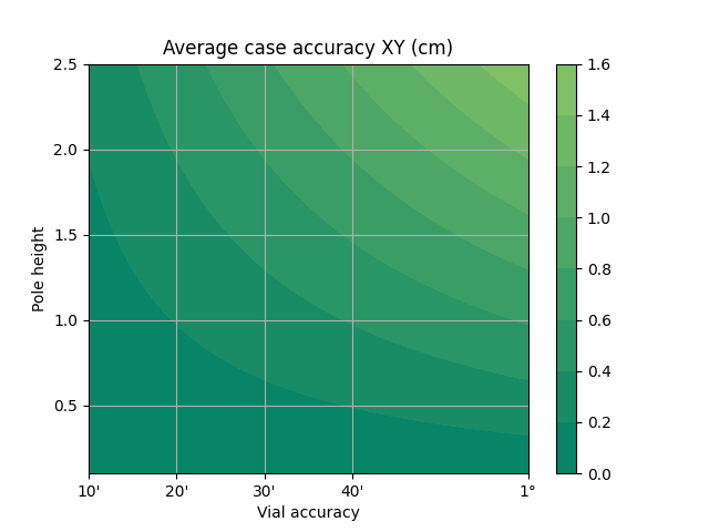
I created this plot to visualise the possible errors. With a 2m pole and 20’ vial one can expect to make a 1.2cm error in the worst case in one lateral dimensions
Here in Brazil there is a rule that obliges the propagation of assembly errors.
To assemble the base, we must consider the error of 2.3mm/m in height, that is, a 2-meter pole will have a centering error of 4.6mm.
The idea was to use a M+ unit we still had laying around for surveying points with a pole. The M+ was mounted on a cardboard box with the LoRa Radio. On the backside a powerbank is mounted with velcro. We use a 10cm extension rod and stuck it through two holes in the cardboard box and mount the antenna on top of the rod. This allows to us to mount the M+ on the survey equipment similar to the RS2, store the whole thing in a case, and there is no need for connecting any cables during setup.
No, at least not intentionally. The antenna is the regular multiband antenna with a 70mm x 70mm ground plane (Everything, on top of the 3D printed part in white). The steel plate at the bottom was there as a guide to measure the inclination at certain positions on a site. I’m really not sure how/if this will affect GPS signals.
Instead of “doing the math” I suggest you actually measure the error a 40 minute bubble level can create. It’s no where near 2.5 cm for a 2 meter pole. More like sub-centimeter. I checked one of my poles and the horizontal movement at the top of the rod was about 1 cm when the bubble was moved from dead center to touching the edge of the circle. To get a 2.5 cm error the bubble will be in the neighborhood of half way outside the circle, but what surveyor thinks that’s an OK practice?
Of course your rod needs to be straight and the bubble calibrated, but a 40 minute bubble level isn’t going to add more than a few mm of error. That said, I do have a short pole (1.5 meter) with an 8 minute bubble that does better, but often other parts of the process have much more significant errors.
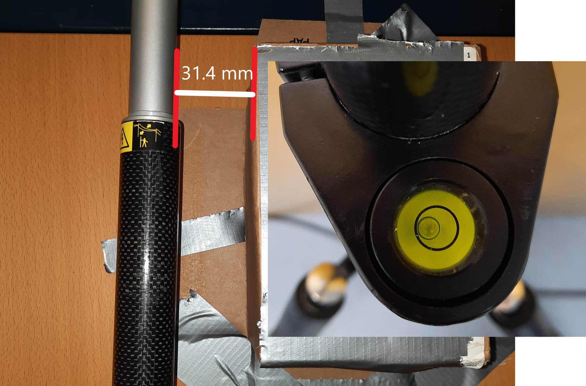
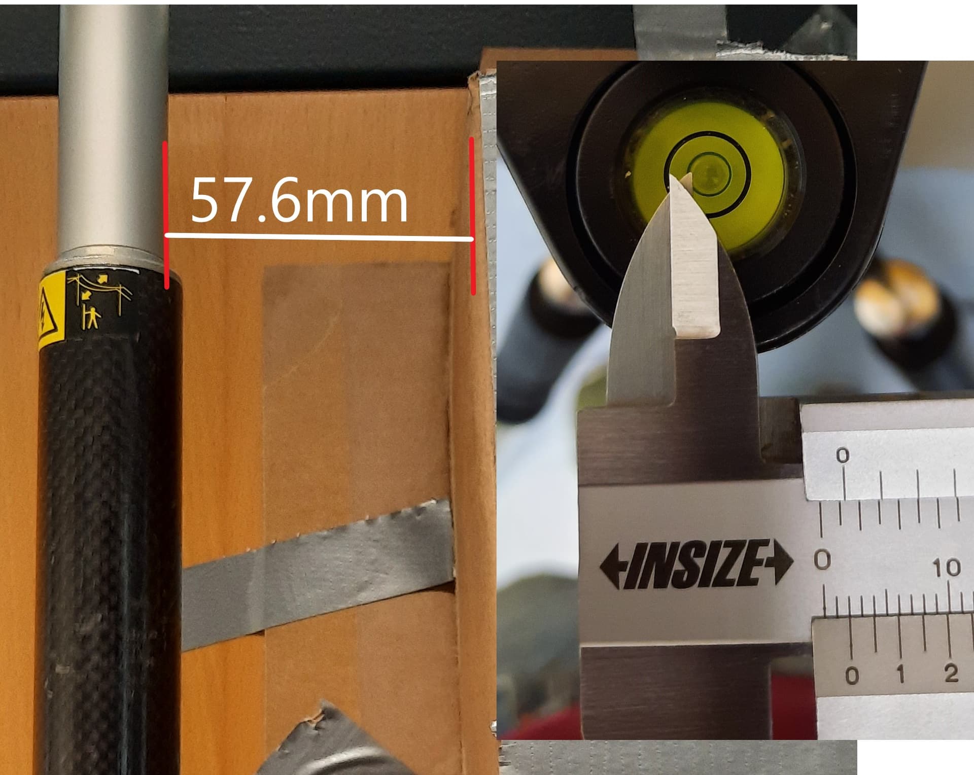
Sure, it makes sense to test whether the theory works out. I setup the pole (2m) right towards a door such that it can move only one lateral direction. I mounted a cardboard box to the door in order to have a reference and a extension to have a flat side instead of the screw terminal. First the worst-case setup with the 40’ vial:
The lateral difference between the setups (57.6mm - 31.4mm) is 26.2mm which is 0.3mm to what the model predicts. Could it be that the vial you tested is a 20’ vial?
The way to determine the sensitivity required is to identify the maximum off-angle the application can allow while still operating as intended. The accuracy at which users can centre the bubble in the vial should also be considered, which is usually assumed to be 0.5mm
So the 26mm is the worst case we can have with a 40’ vial and using the 0.5mm as average case would be 5.8mm error in one lateral direction and 8.2mm in XY.
Jonas, it appears that by your own testing, if using pole with a 40’ vial, which is adjusted properly, and a user is diligent to keep the bubble as close to center as they can perceive, it is most likely that lateral error will be less than 1cm. As others have mentioned, error introduced by other factors is probably of greater concern.