DIY offset rig with Disto laser. Survey & Stakeout !FINAL!

DIY offset rig with Disto laser. Step 1 Survey

Had an ide and thought i would see if i got any usable data out it.
Goal would be to survey points were there is not possible to use GPS, under trees and areas with poor or no satellite coverage. Should be a familiar problem. I hope to get sub dm accuracy.
Second goal is to stake out points under the same conditions, but i will come back on that later.

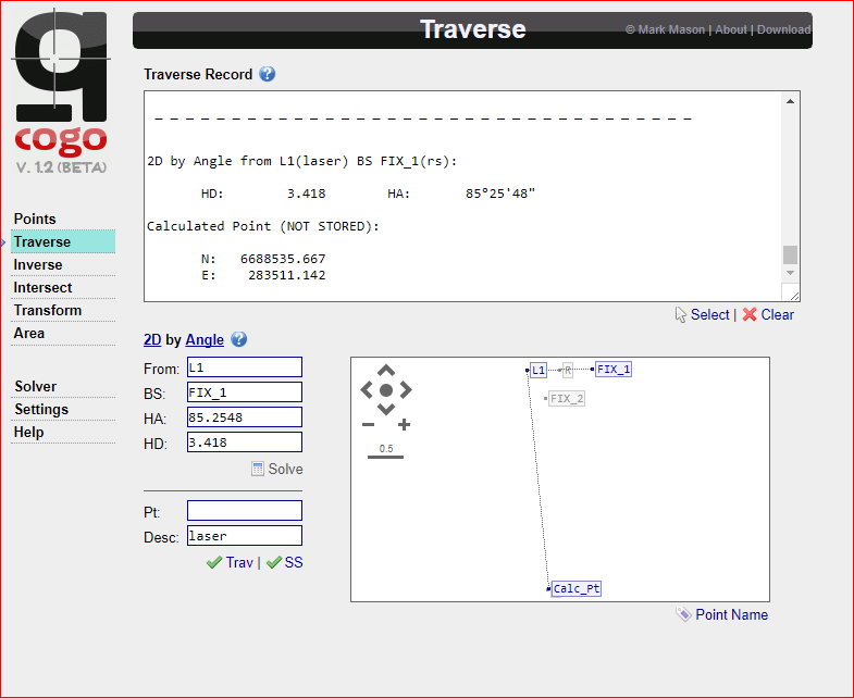
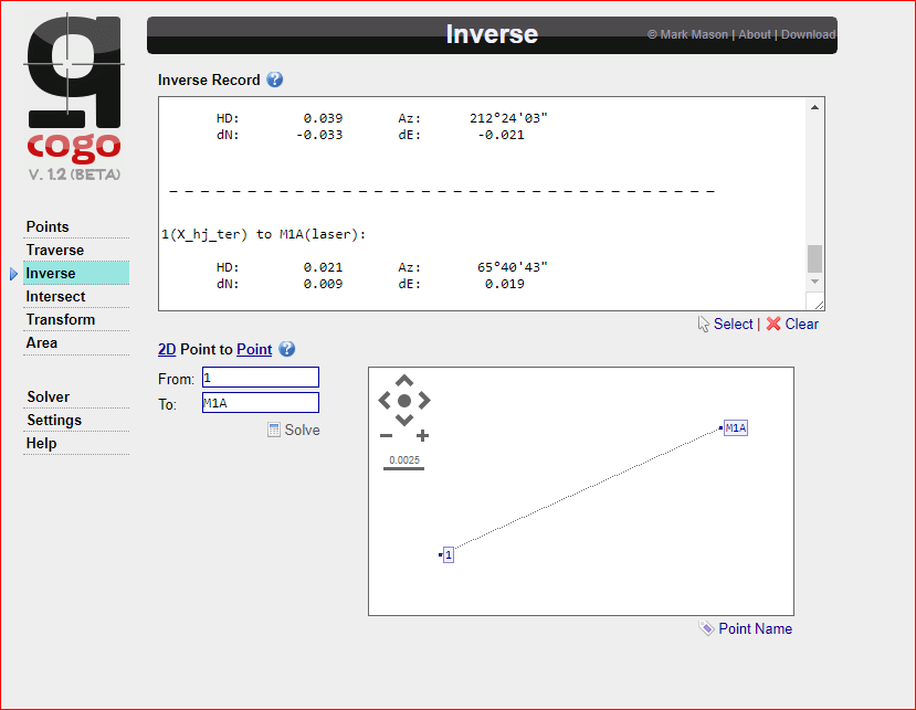
I would use Reach/RS to set refrence point and calculate backsight/traverse with online tool like Q-cogo. Its basically pure math and should not be a problem but different application has some deviation, like accurate position when calculating angles and elevation with laser like Leica Disto D510. All these error ad up and it is crucial to keep them at a minimum.

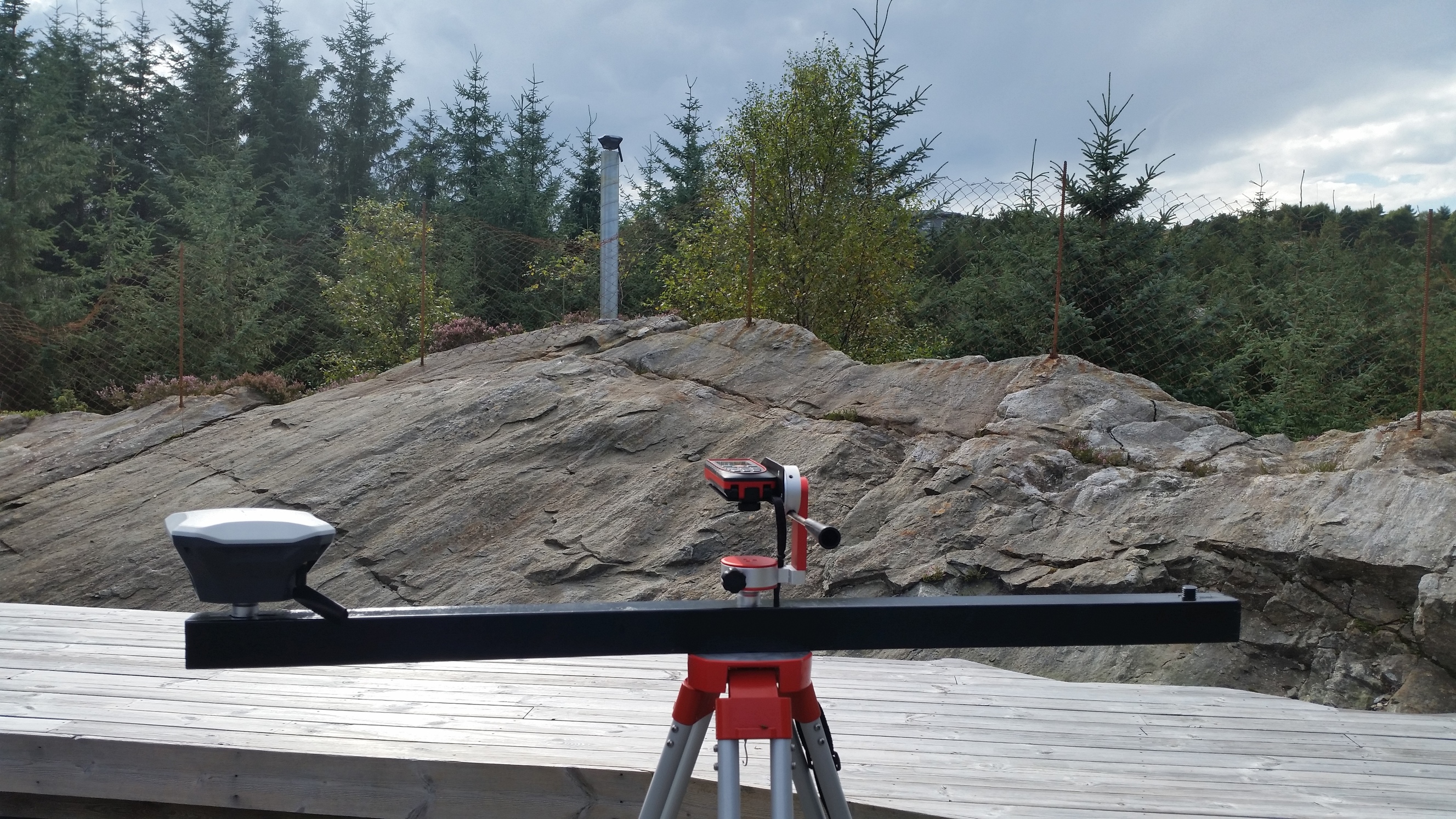
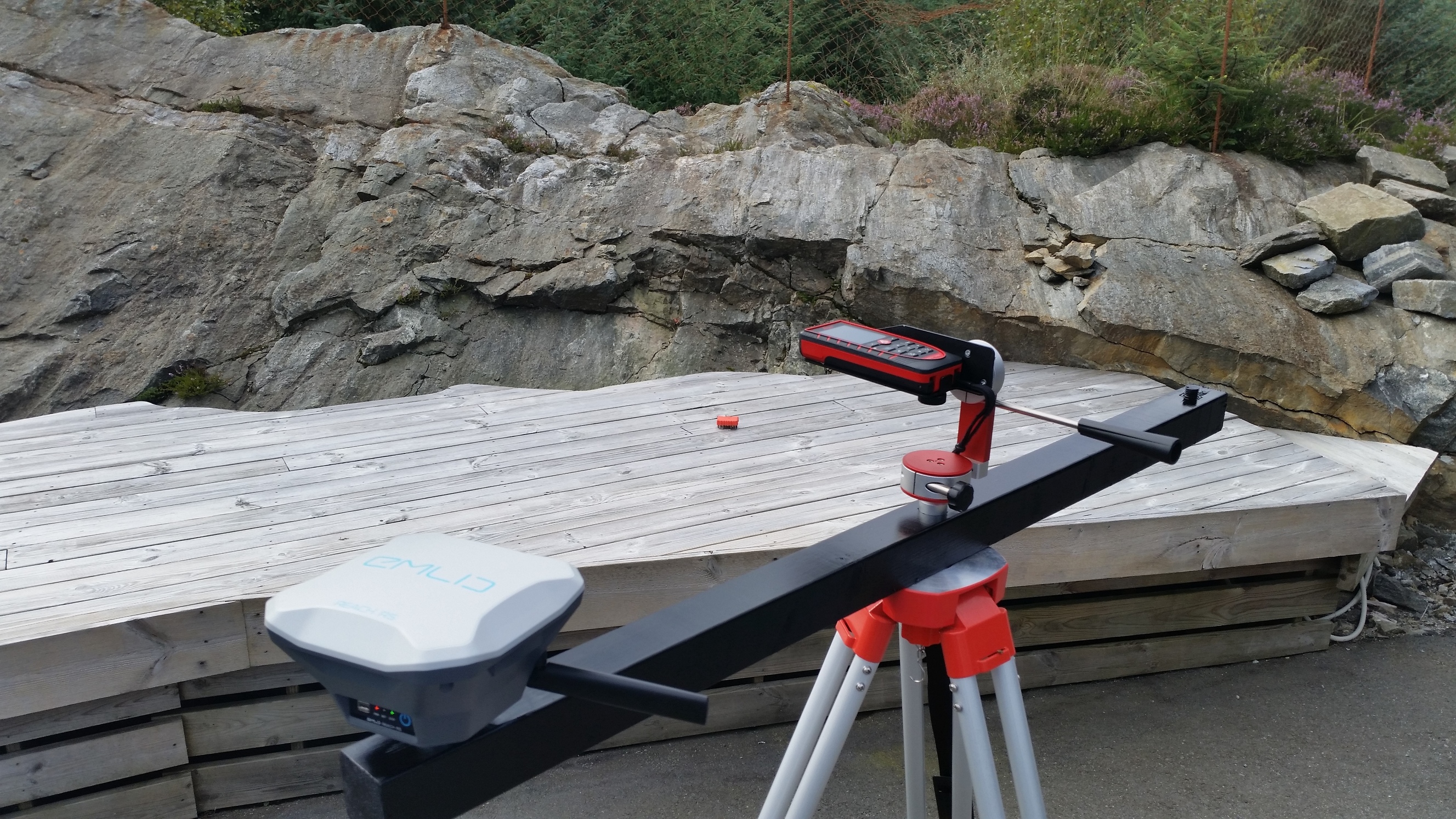
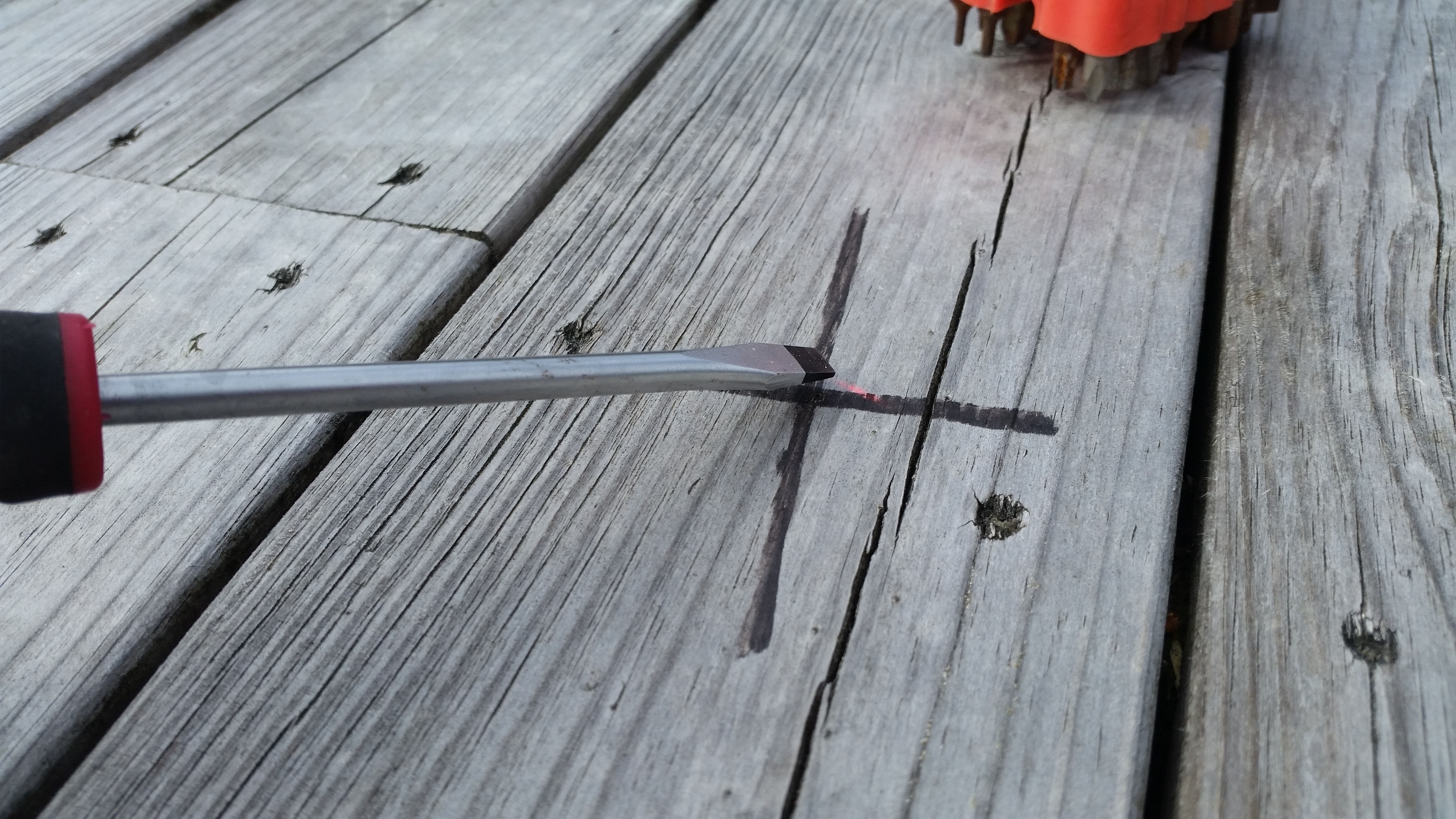
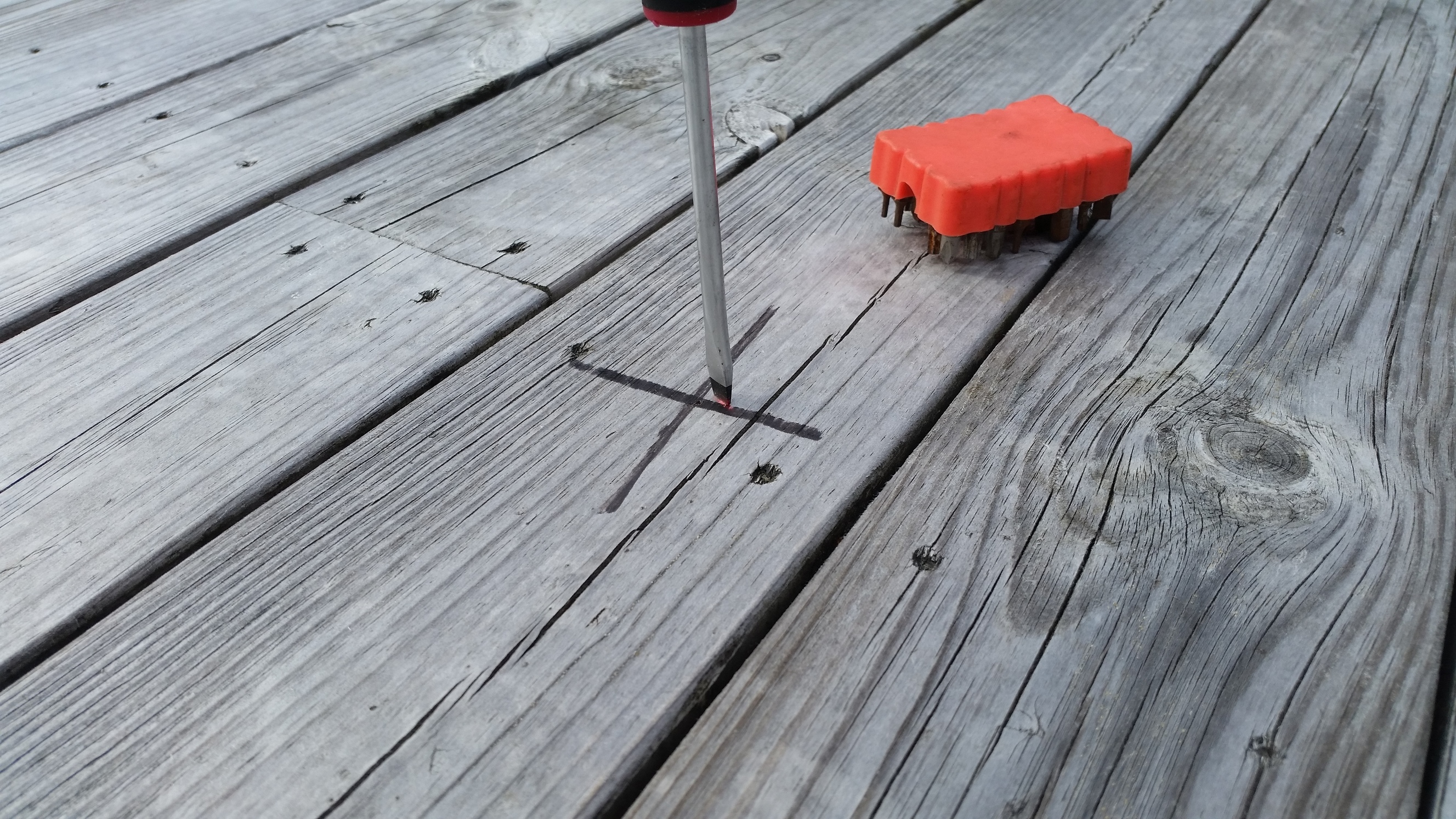
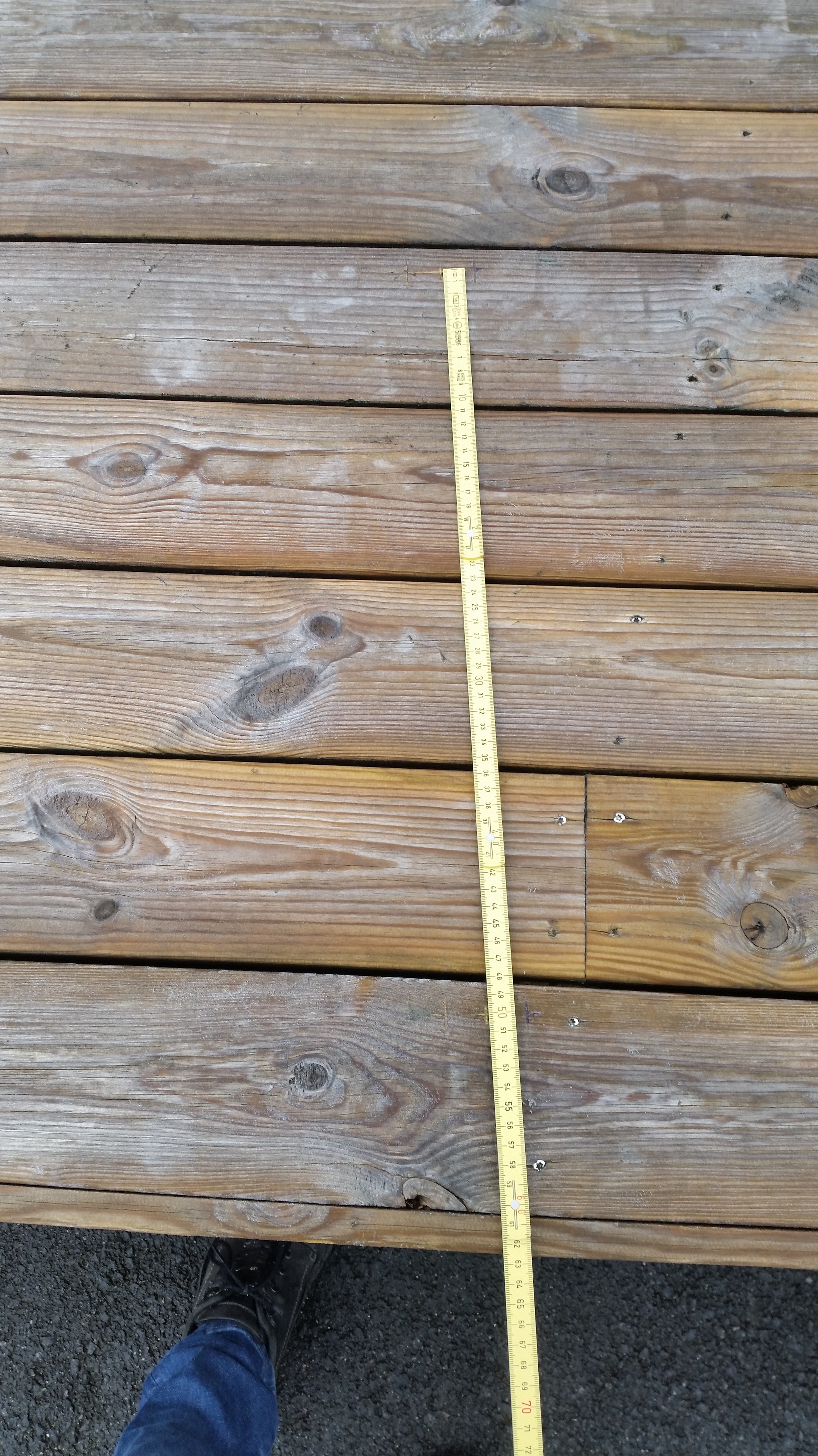
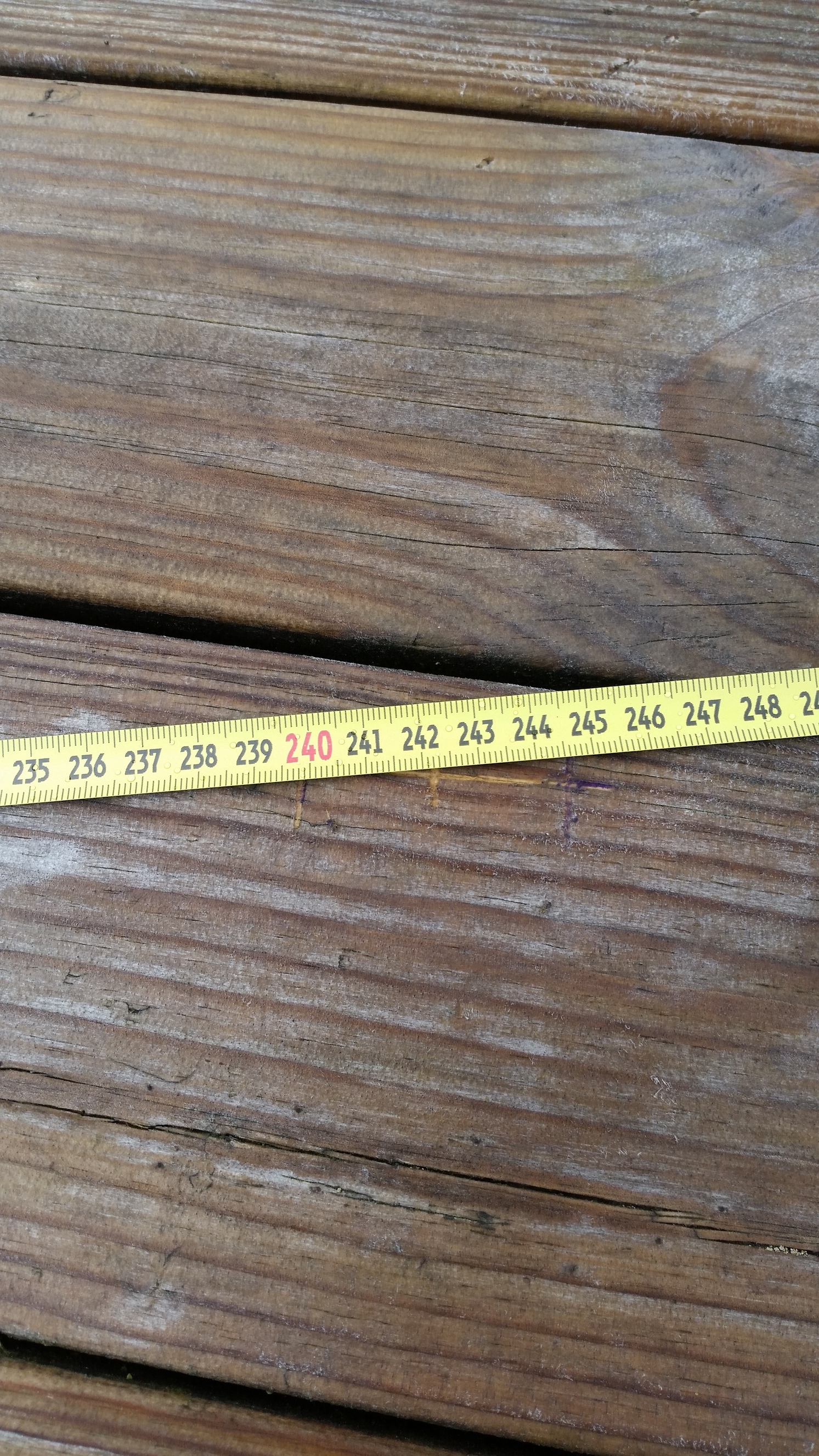
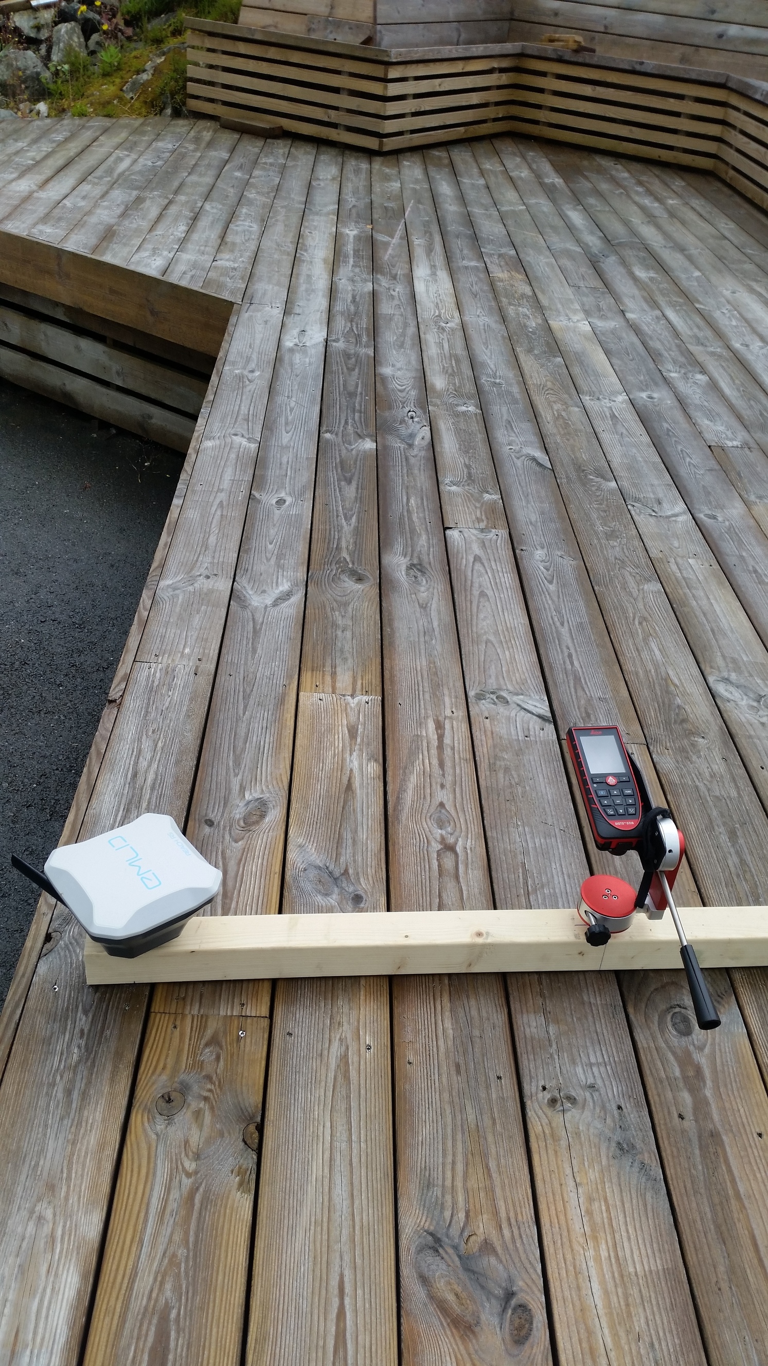
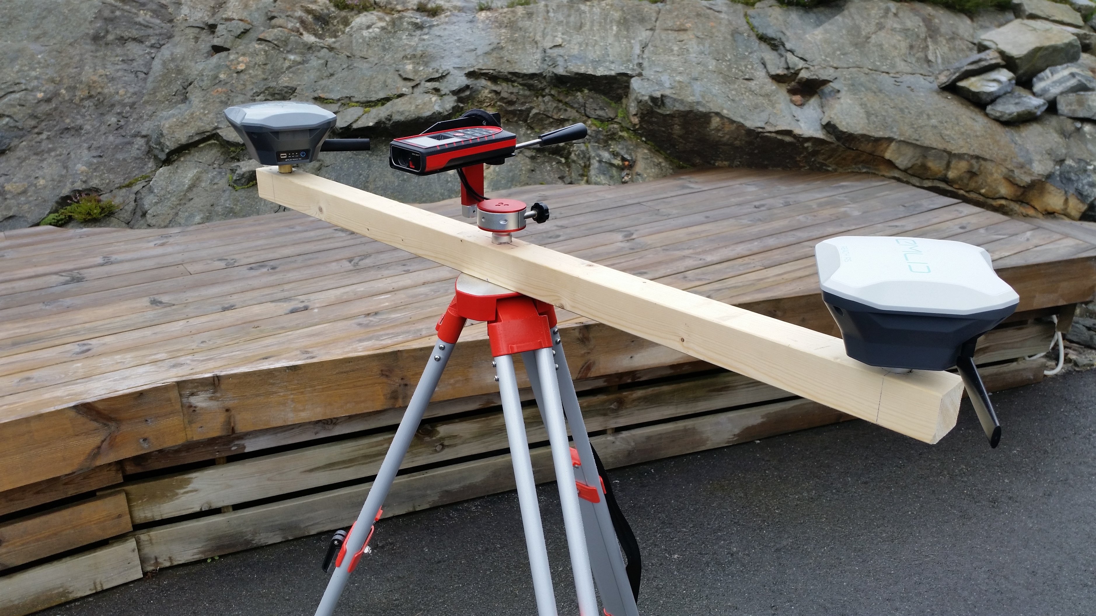
Following is pictures during assembly


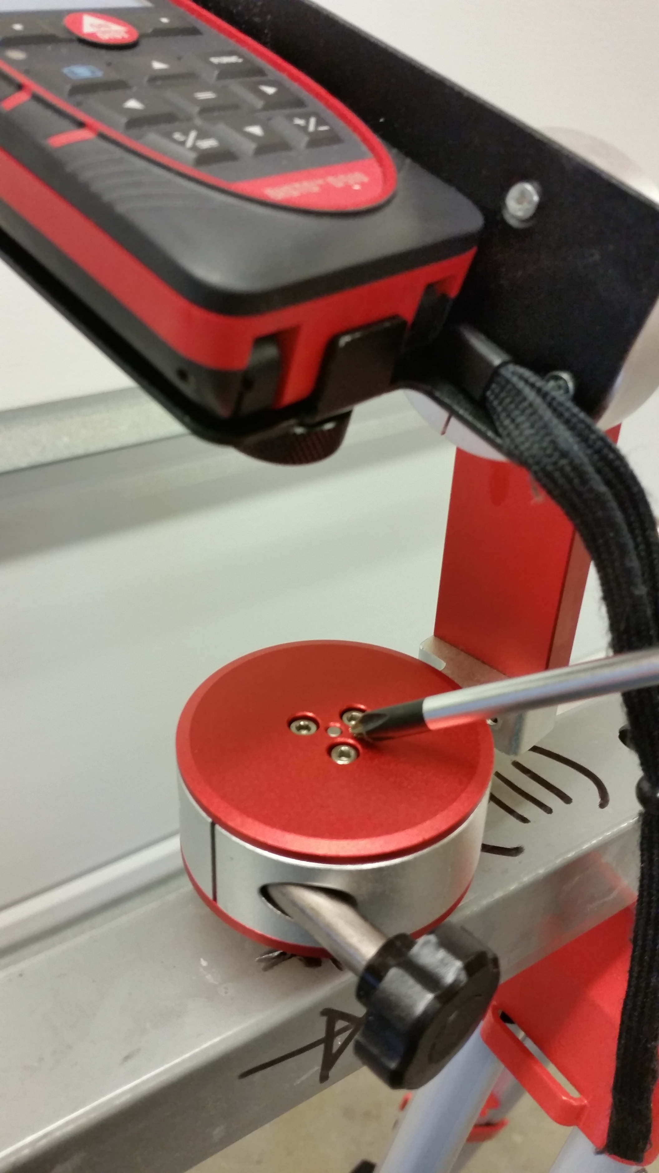
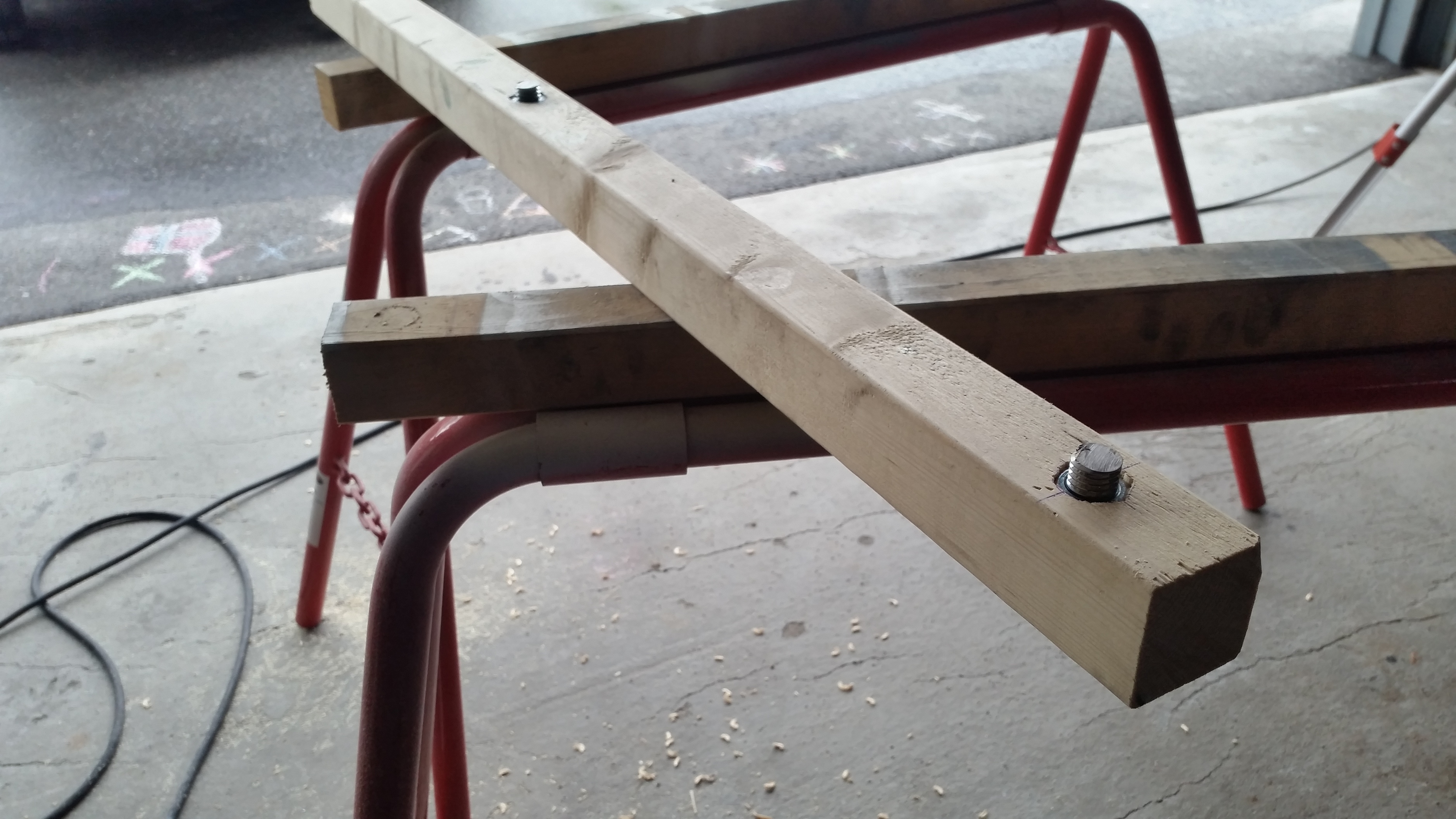
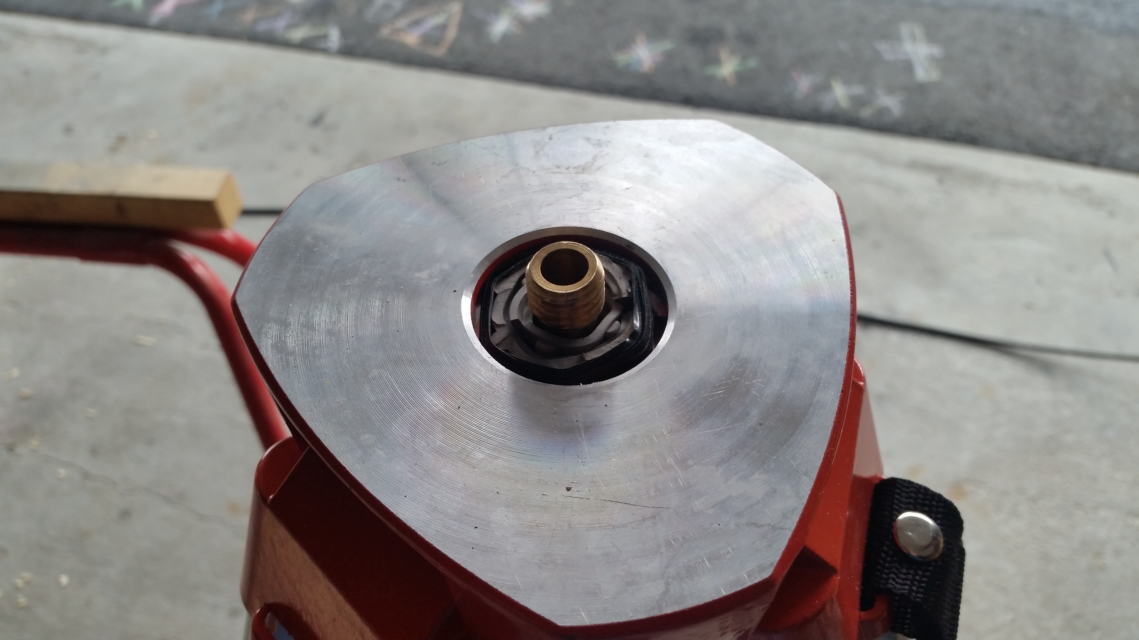
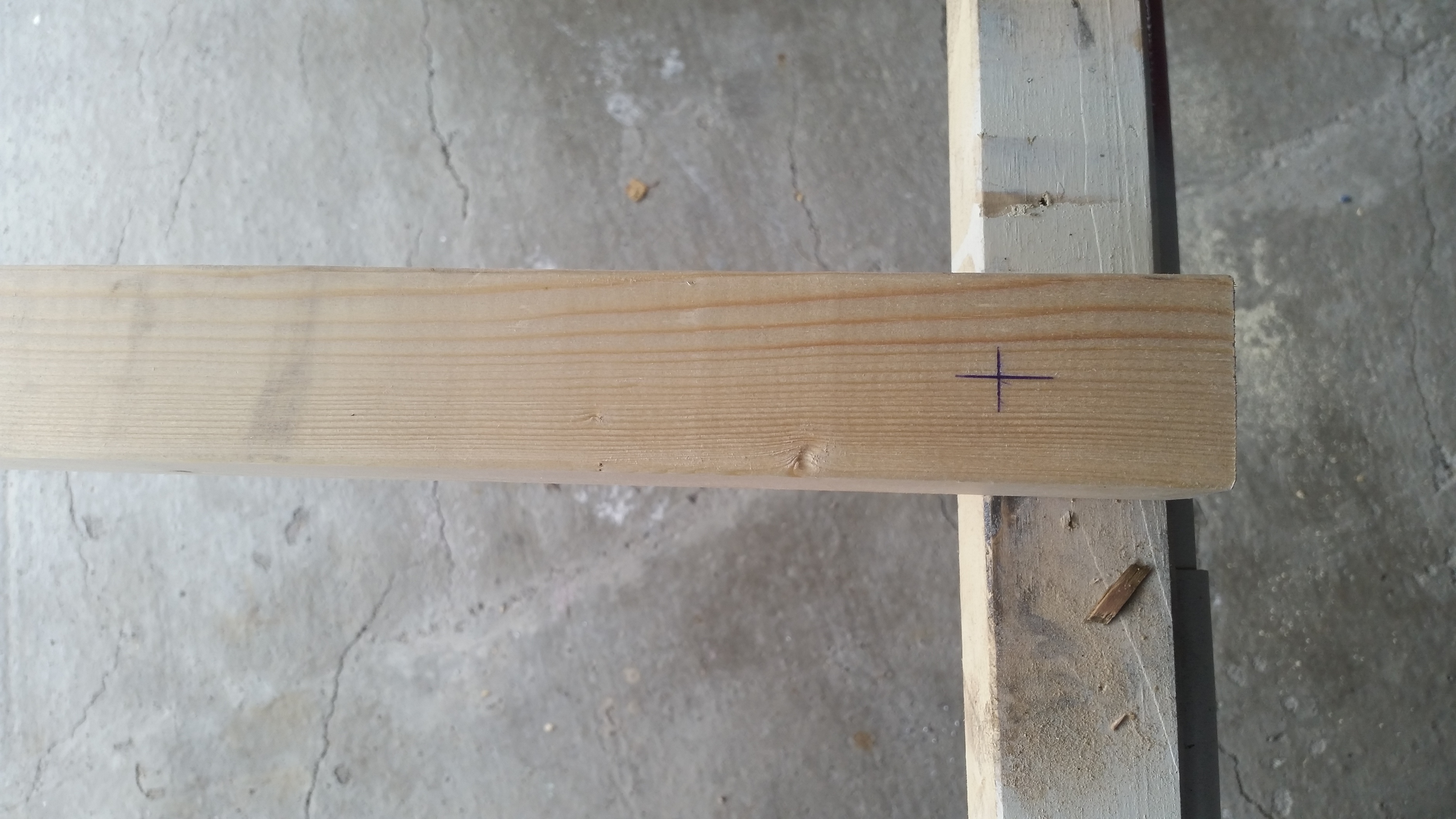
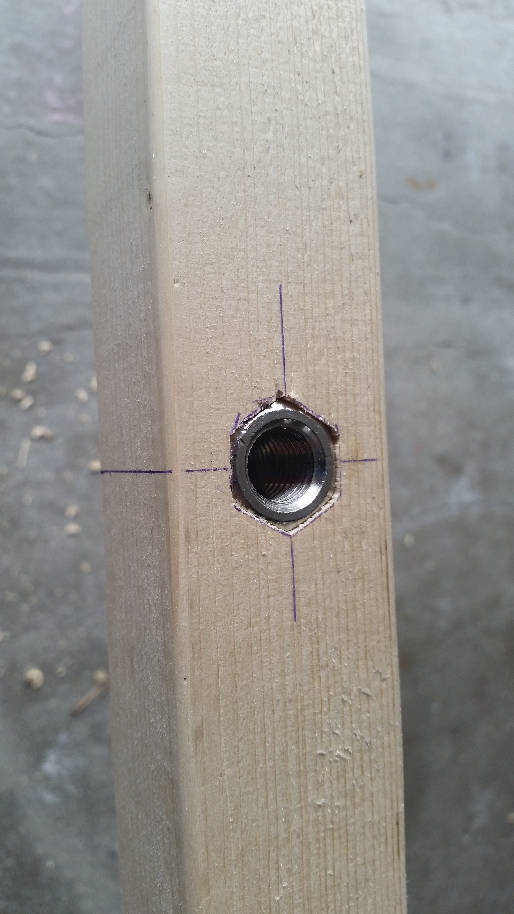
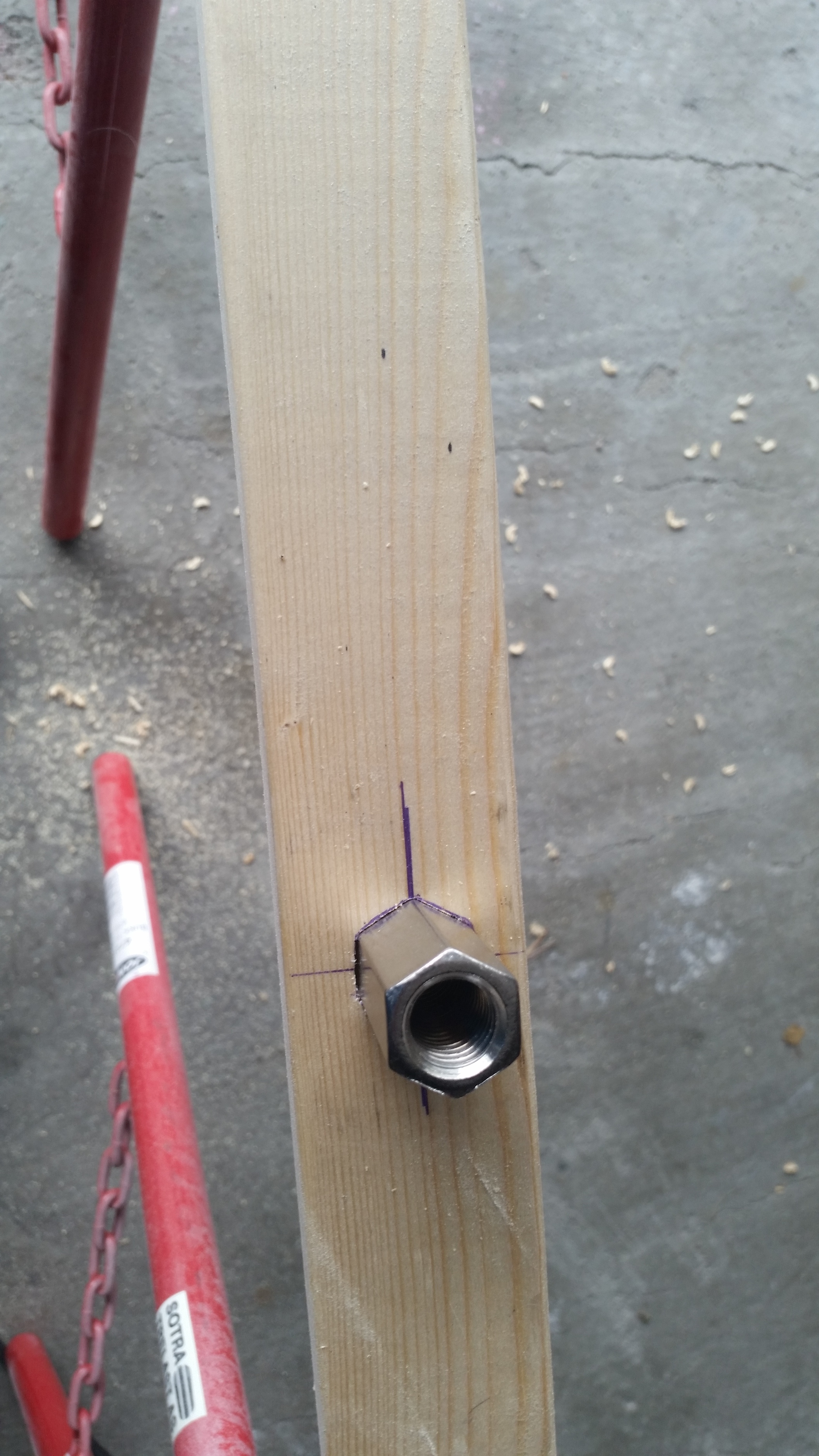
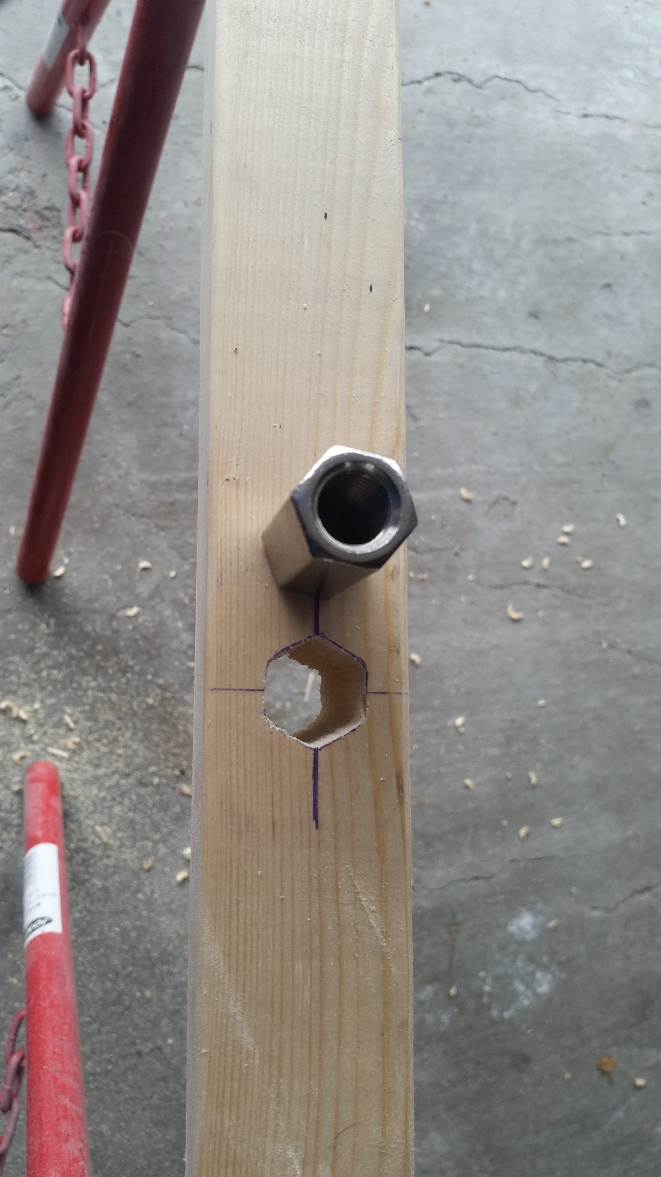
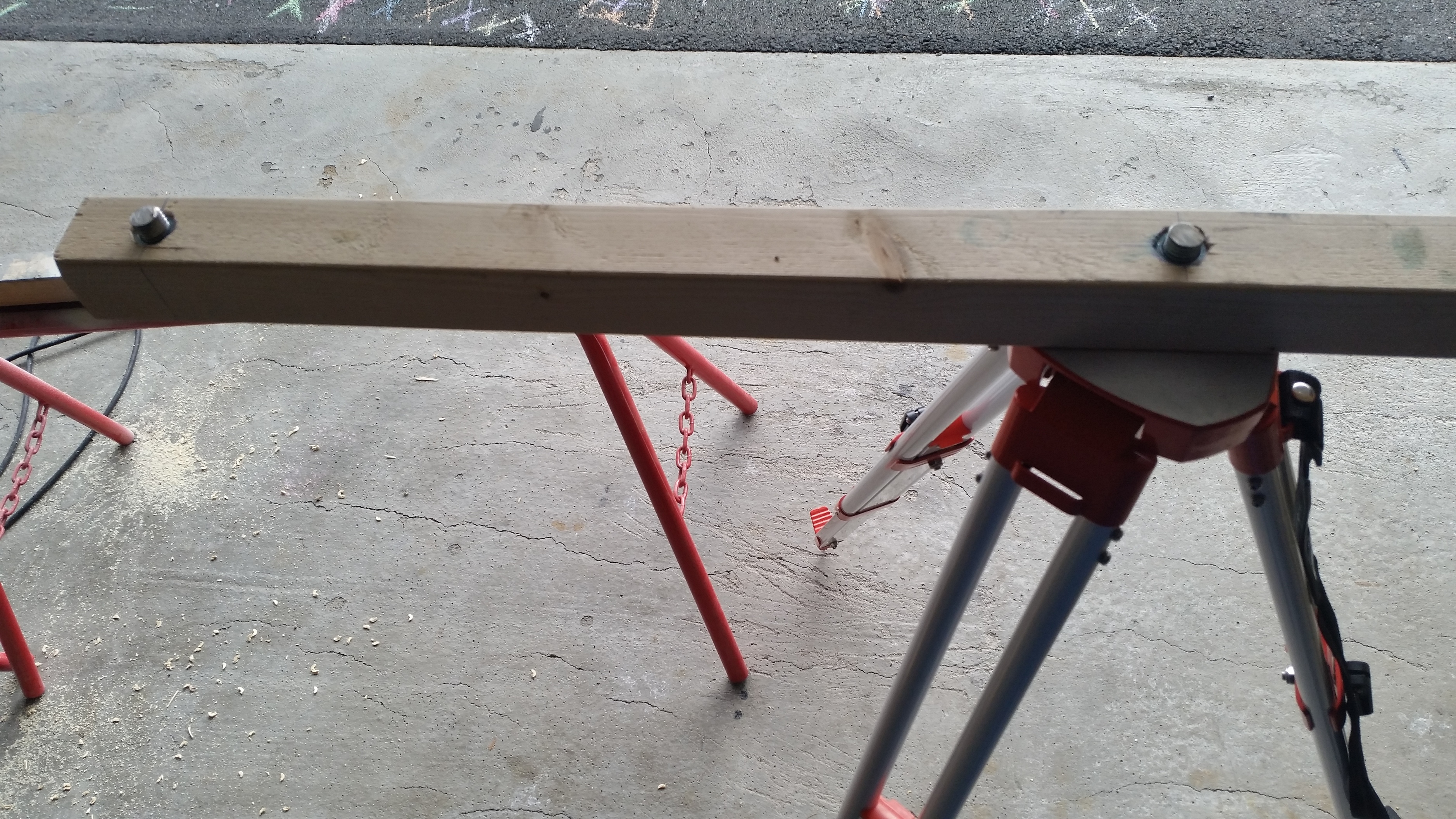
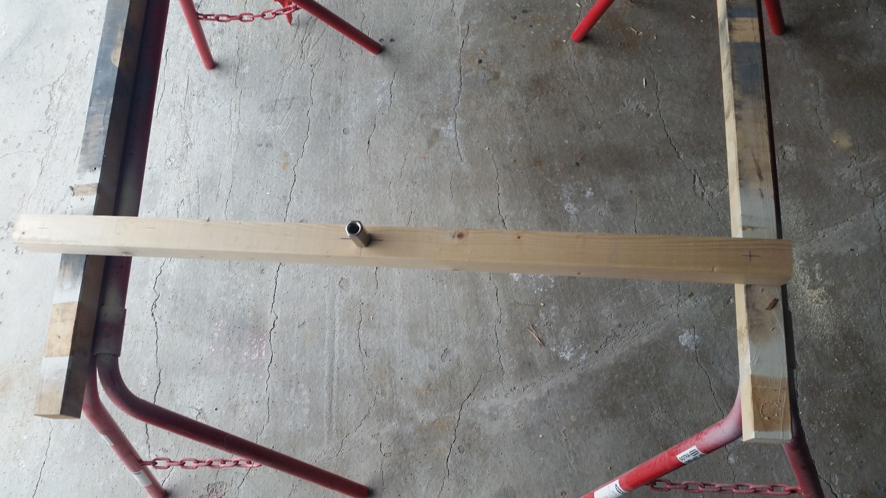
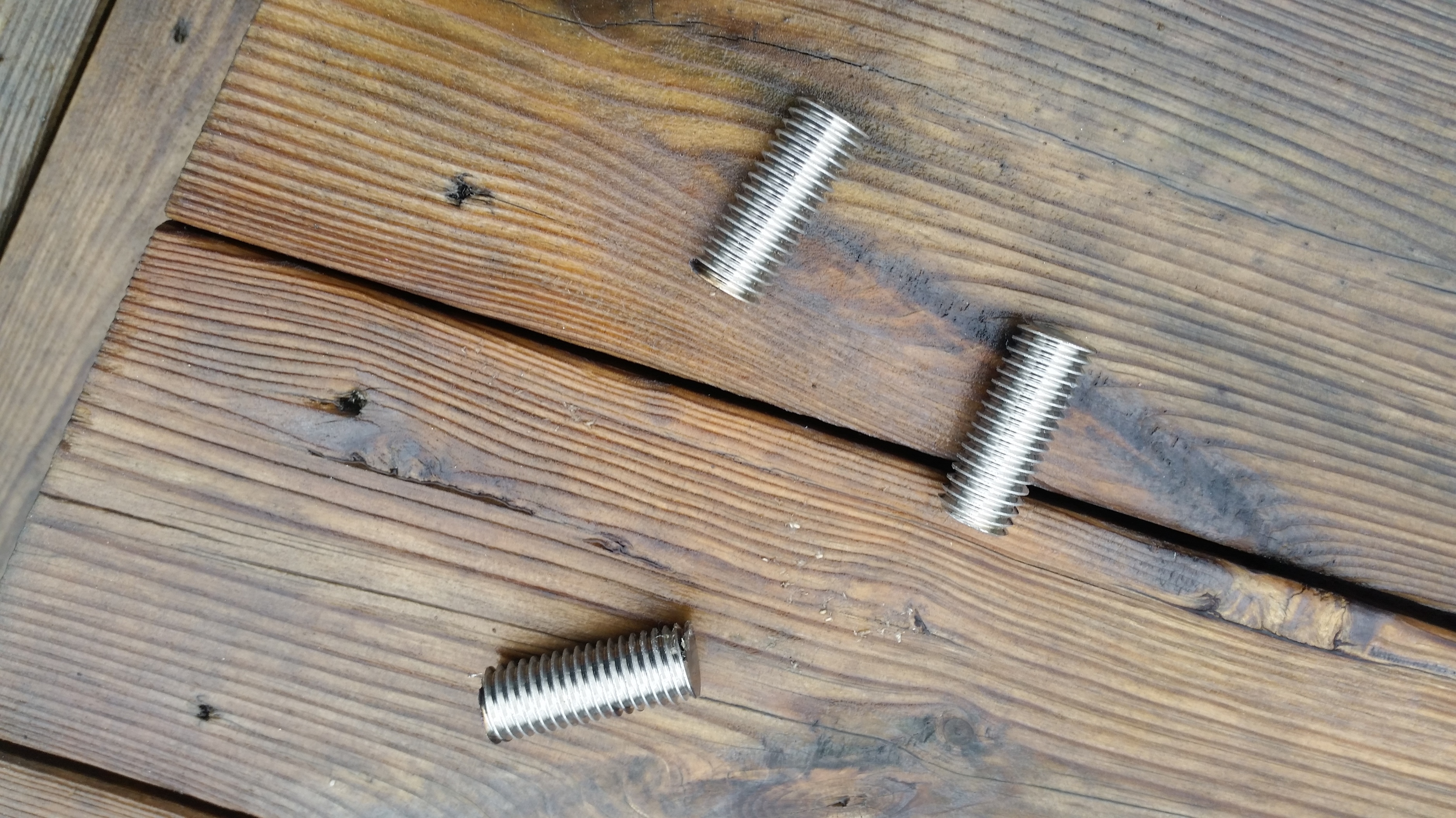
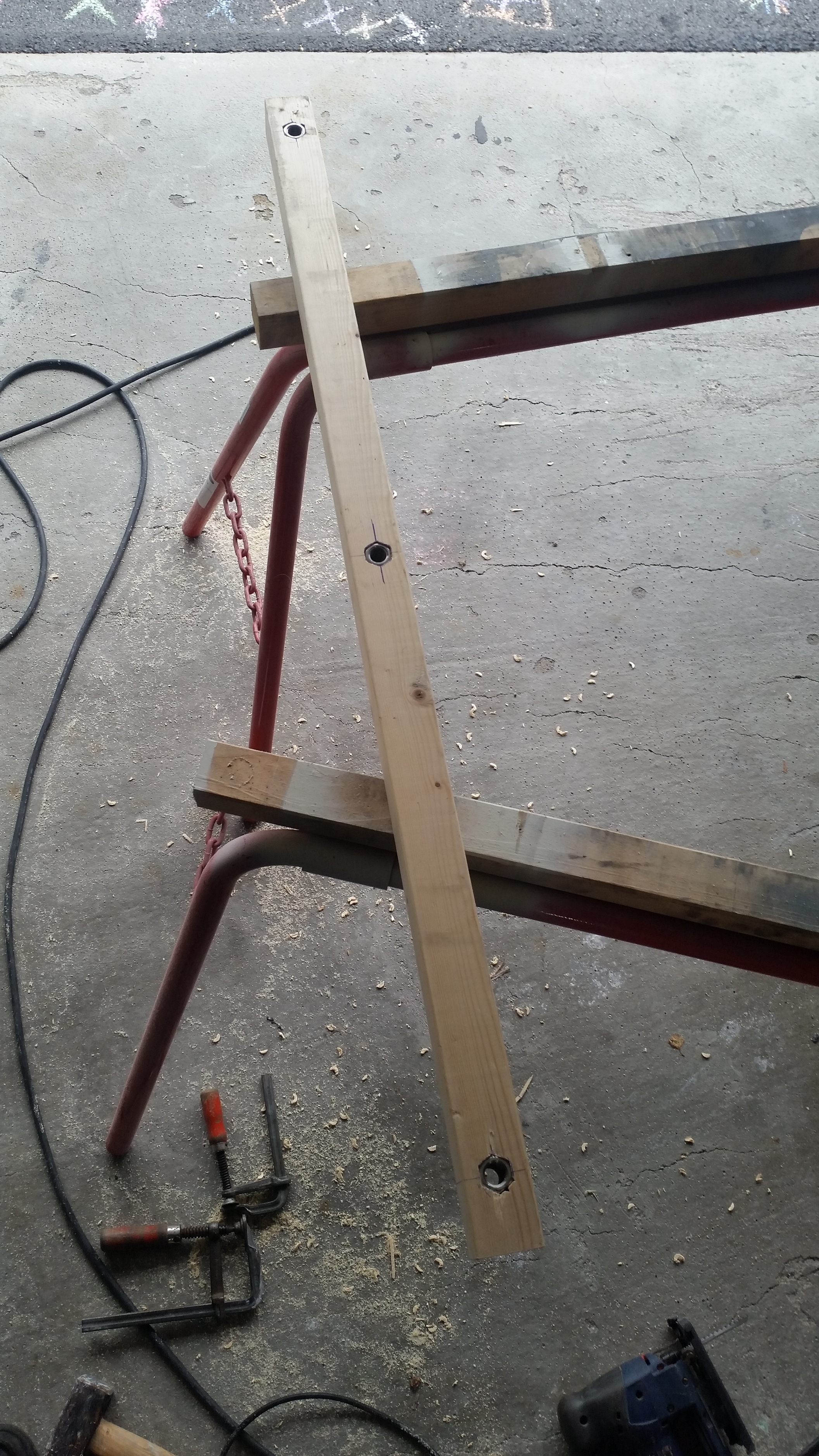
I made a rack of 2x2 wood. Is has 5/8 mounts in a straight line, 500mm apart.
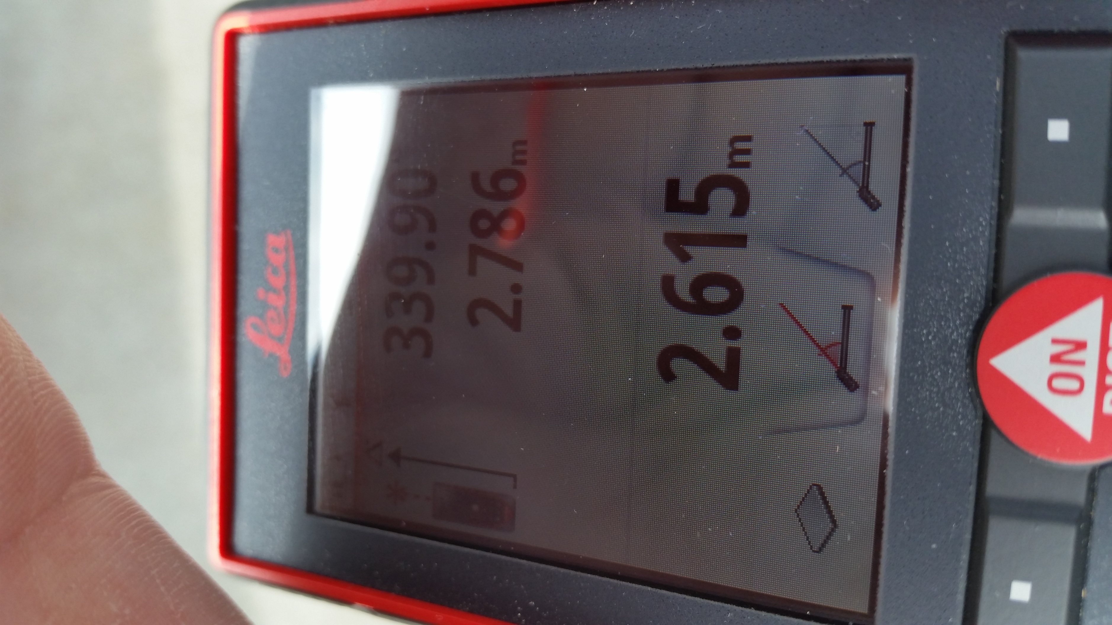
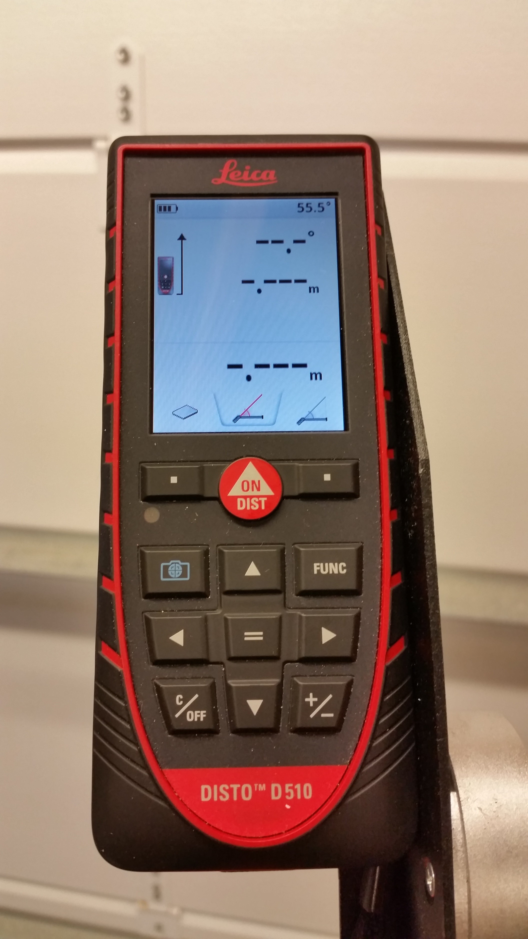
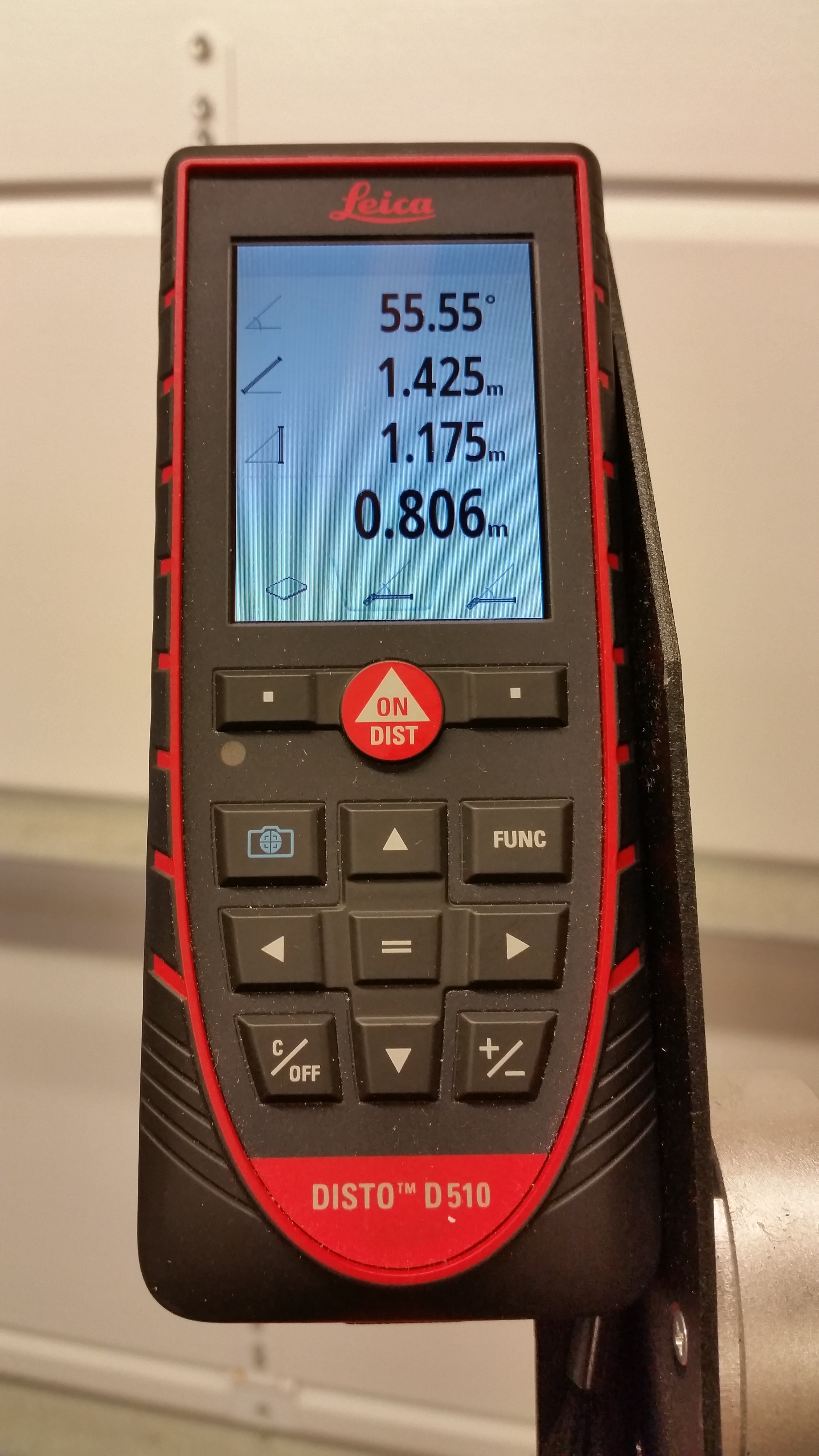
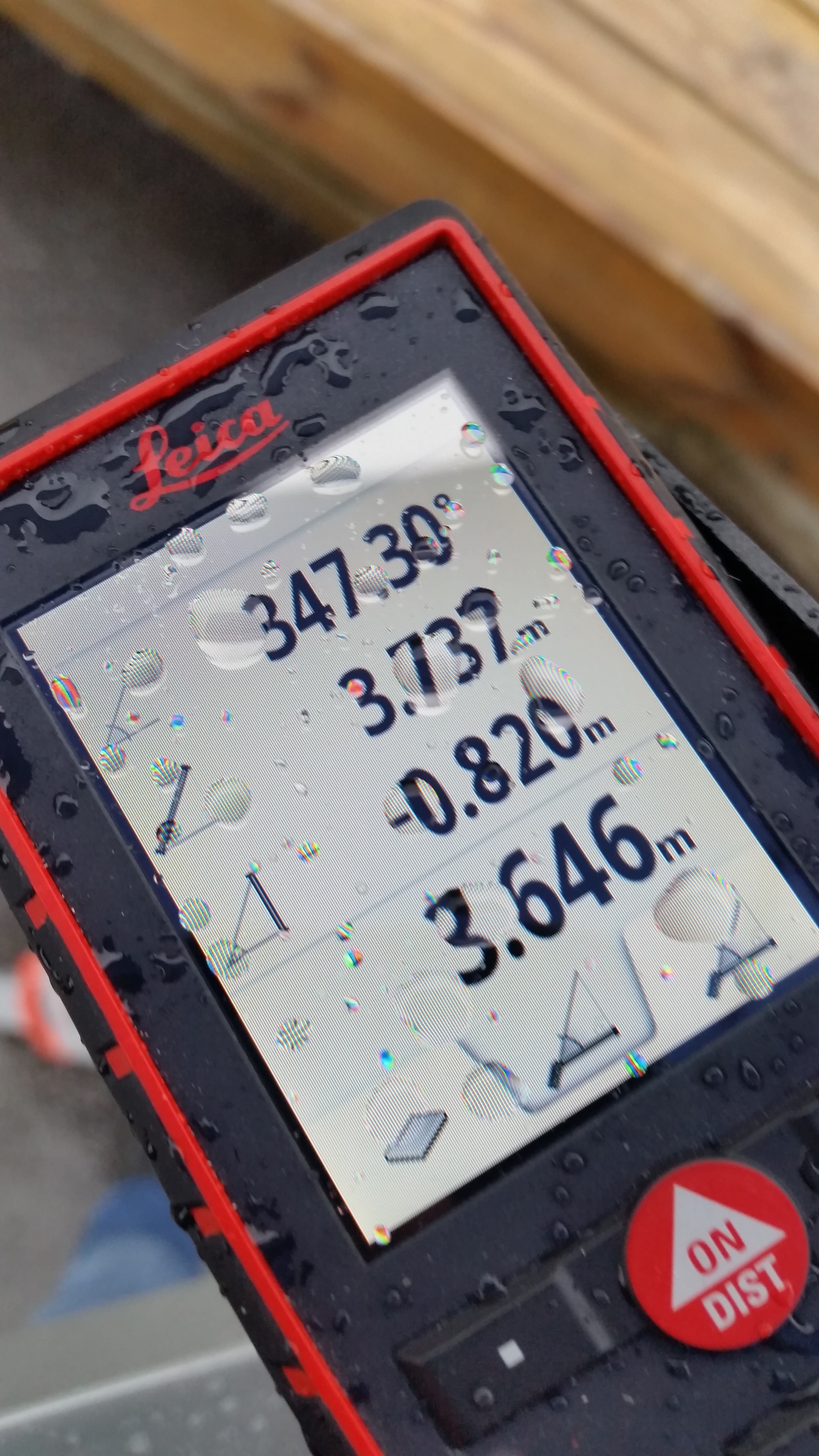
D510 is mounted with a bracket that spin around its vertical, horizontal axis and also elevate without shifting away from origin mount. This helps with accurat slope measure and is calculating the horizontal distance on the fly.
It has some other nice features i get show more of with the stake out section…

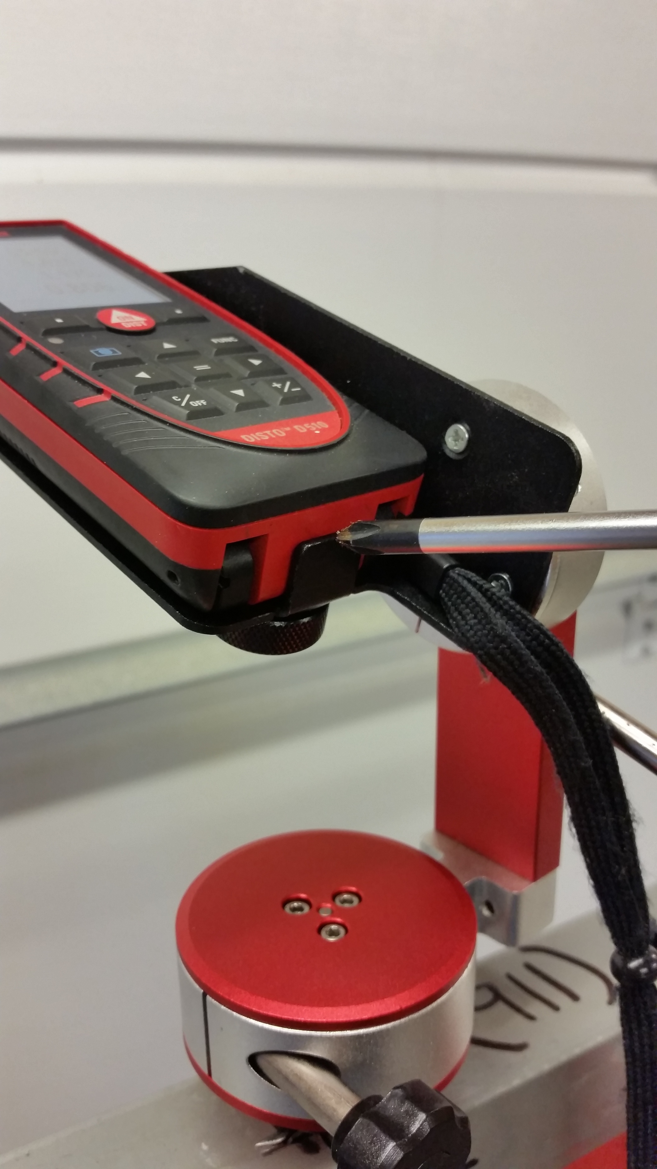
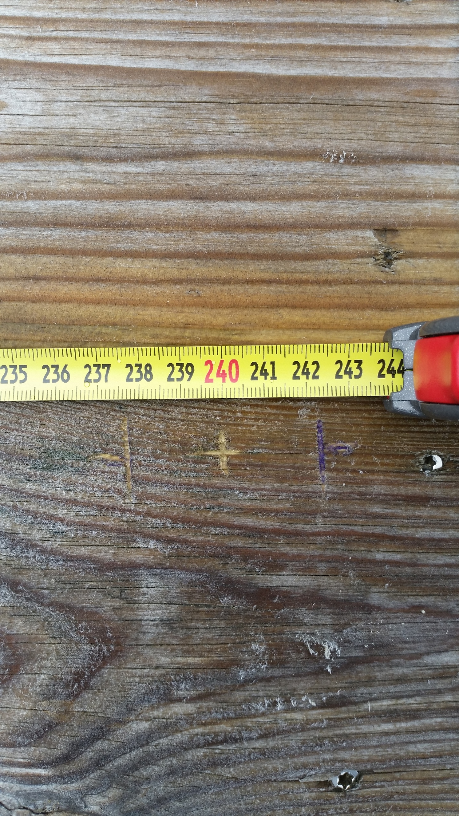
Next are some pictures from a place to calibrate and measure the angle Disto braket is mounted. Bracket is set in a random angle and tightn fix. When the rig is mounted on a tripod it will rotate on the tripod center mount and elevation is adjusted on the disto bracket. So it has 360 rotation and about 70degre elevation up and down.


Now, Q-cogo is an entire chapter so i am not going into that.
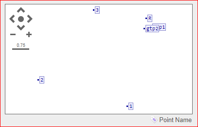
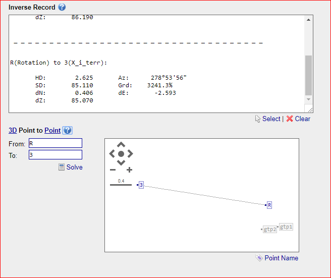
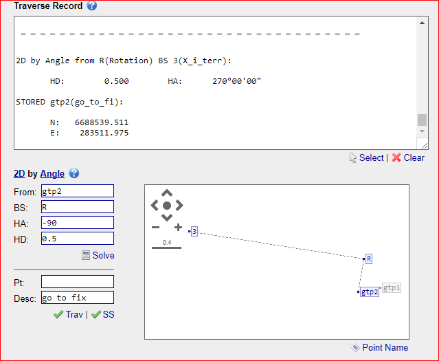
Here is a screenshot showing all points.

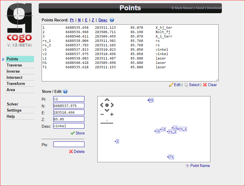
As you can see from the picture, calculated with disto alsmot line up with surveyd gps points, ( M1 and T1). They few cm off.
Here is all point zipped. All you need to do is copy content in file, hit edit button under points menu in Q-cogo and past into marked window and finish off with edit button again. Now should all points show up like above.
3d.zip (357 Bytes)

Short descriptions of pointlist
1-3 are surveyd points and should be accurate
RS 1-2 are position of RS during measure and is rotated around tripod axis.
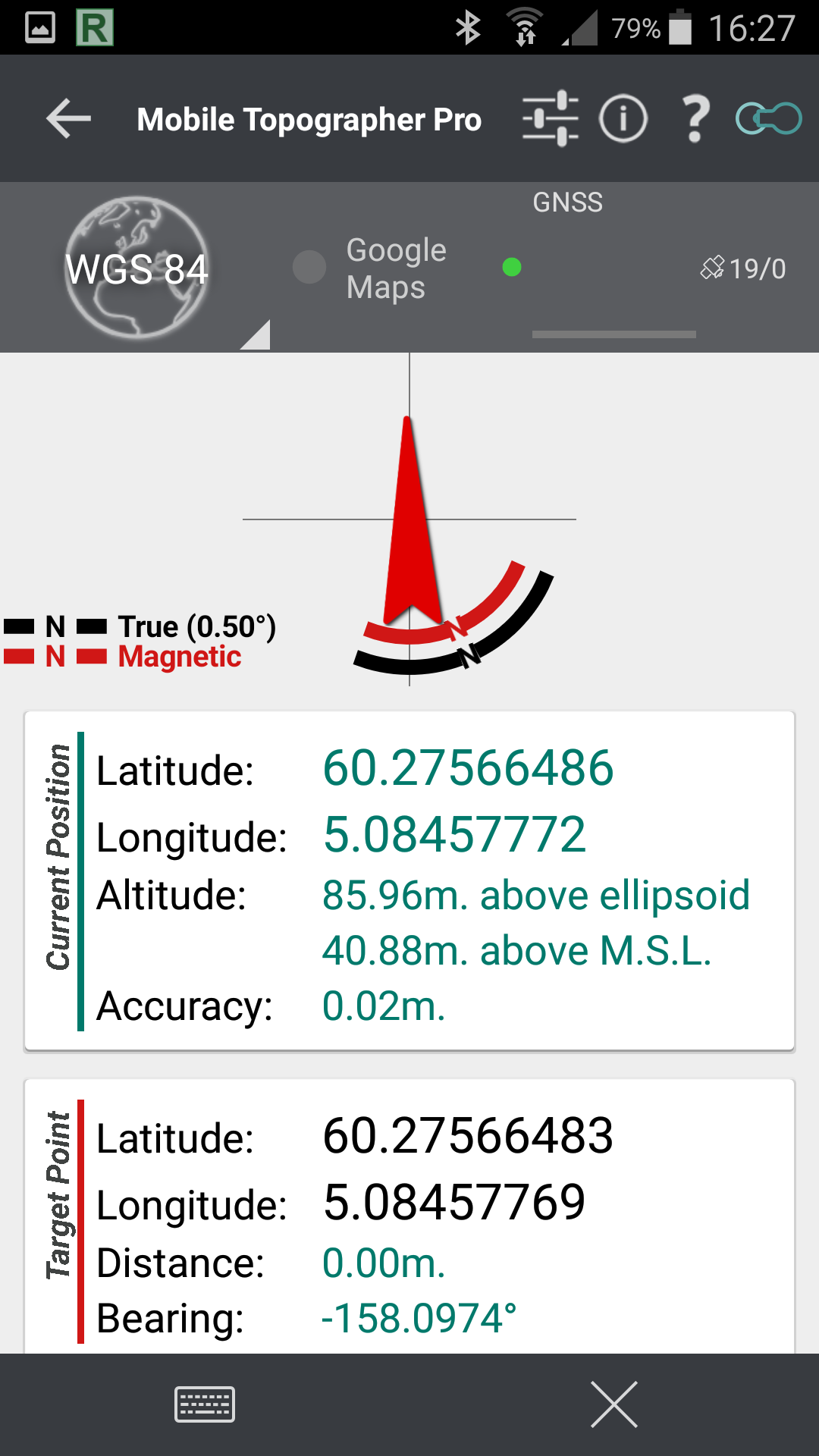
L1 is calculated position with Q-cogo tool.
V1-2 are surveyd points during calibration of disto angle.
T1 is calculated position of nr 1 with Q-cogo
M1 is calculated position of nr 3 with Q-cogo

Next step is to move Disto to the end of rig, 1m apart instead of 500mm from reach to get better accuracy.
Right now, 500mm from reach it could generate large deviation. Just few mm of here would be cm further out.

To sum it up. Things look fairly accurate for something home made to be. Hope to narrow it down a bit more by increasing the distance between disto and Reach. I also need to calibrate the d510 it self. It has a buildt in function i need to carry out Hope this will better the elevation angle.

Well, thats it for now. Enjoy.

Be sure to check out Q-cogo. It has some nice features.

9 Likes

Well done @TB_RTK ! You seem in all your posts to have such fun with your Reach ! :smiley:
One day you will turn into a surveyor. It is the perfect job for people who like measure and play with numbers. And the equipment is so fun to operate ! Robotic total station, ultra precise IMUs, laser scanner…

@Pascal_P Thanks. Hehe fun, indeed. But also frustated.
In my profession 1+1=2 (archicad), but here 1+1= 2,4 with 30% chance of beeing 2,7… :flushed: And that with clear skyview :stuck_out_tongue_winking_eye: That doesnt cut it in my world :joy:
So i tend analyse every single error i get to find the cause of out of line work.

2 Likes

Yeah ! Surveyor culture is all about error and uncertainty theory, and how to minimize them. Once you understand that your measure will never be exact, but only “truth +/- e” , you have one foot in survey world.

5 Likes

I found several minor deviation with my tools.
1000mm is actuall 1002mm from center reach to Disto.
D510 was about 1 degree out and 2mm off compared with 2m actual measured line.
I got it calibrated and a new test is up to see if that would impact accuracy.
I also need to ad 50% user error to the total computation/calculation :rofl:

Ah, thats gonna be a tough one

2 Likes

Ok, some progress.
After adjusting ref. post above. I get this result
Survey point nr 1 and measured point M1A is 21mm apart
Point 3 and M2A is 39mm apart.

Would think point 3 that is closest would deviate less then point 1. Anyways, happy so far. Next time around would see some result increasing the distance and see if it still is within sub dm.

Updated the 3d file to contain latest points. 3d.zip (380 Bytes)

1 Like

Initial workflow finding the angle of L1 and refrencepoint RS/FIX (point where disto is measuring from). Once this is solved, rest is easy.
I plotted all measures in to this calculator and got me B angle, I transformed degrees to dms here ( Q-cogo only accept azimuth dms in ddd.mmss).
This could probably be done in a single operation with a different tool, its just what i used now.

I now have all number filling out traverse. Result is “Calc pt”

Finding the L1 angle is only done ones, or every time you might think angle has been misaligned.
I can now rotatet and measure as many points i like on the fly by changing the BS (backsight) point which is the ReahRS rotating and getting new coordinates for every turn i make.

And here a shot showing calc pt. M1A and point 1 (gps fix) with 21mm deviation

Final step of DIY offset rig. Stake out

Here is a scenario: E.g stake out a point in an area with no gps coverage. or on a wall etc.
For the sake of this argument i already know all the positions beeing used and had them surveyed.

In my example i need to stake out a point on the ground. This point is marked as nr 3 in the Q-cogo picture

p1

You can download the complete list of points here and copy past into q-cogo, as mentioned in privious post.
gtp.zip (318 Bytes)

This time i adjusted disto laser to give me 90 degree angel to offset rig, this is much easier to handle in cogo instead of azimut values. Rig is now calibrated to TB_RTK standards :crazy_face:

I place tripode nearby without the rig, i then place ReachRS and survey vertical axis of this mount, i made a fittings keeping 5/8 thread fixed to a horizontal position. This enables my rig to rotatet around its own axis. I also have the flat surface of tripod perfect leveled. I now swap RS with Disto

Coordinates from RS is plotted into Q-cogo to create new point called R. R is center and vertical axis of tripod. RS is placed on an known distance from center and i calculate distance from point 3 to R with 90 degree angle to RS. RS is 500mm from R. Picture below shows calculation of distance and new coordinate were i need to move RS to for stake out point nr 3.

gtp2 coordinates is plotted into mobile topographer. I rotatet the offset rig until i reach the destination.
From the picture you can see how topographer displays 0.00 to target. I would prefer 0.000 values.
Offsett rig is now oriented.

Next up is to adjust elevation of disto to show calculated horizontal value from R to point 3 (2.625m)

In a hurry i almost hit the exact spot. Minor tweeks would get me almost to the measured point.
Screwdriver marks where laser dot hits ground, just mm of .
Now, show me a robotic totalstation for the price of 5$ doing the same thing :sunglasses:

Sorry for any bad English. Typos is corrected later…if i find any

7 Likes

Wow - super nice project! Would be interesting to see it in combination with the new s910 3D distro :slight_smile: https://lasers.leica-geosystems.com/global/disto/s910

I would be interested in combination of EMLID antenna with Leica Disto S910 as well. Like Leica Gamtec.

Problem with the S910 in combination with the Zeno 20 is that for the same price you can buy a total station with better precision, more rigidity etc…

1 Like