I purchased two Reach RS+‘s a few months back but was just able to get out and collect data last week for the first time. This is my first time using this equipment and I have watched all of the videos I can find on setup and use of the equipment. the equipment worked great in the field but I can get the data transferred into CAD so I can use it. I was able to export the data into a CSV file and import it into Cad as points. Everything seems to be orientated right but the scale is way off. For example, one of the measurements is coming in at 0.02" but it should be 11’. Any suggestions?
This could be a projection issue. For instance, if you import the points and define their coordinates using the geographic values (latitude & longitude), this would yield very small measurements if the CAD units were, for example, set as millimeters in a cartesian coordinate system.
WOW, Thanks for the quick reply. As far as CAD software, I’m using Autodesk AutoCAD 2020. I tried many different units several different times and the scale is always off. I used WGS 84, EPSG:4326 for my Coordinate System when collecting my data.
If you’re using Reachview 3, you could setup your survey project with a projected system (for instance a local state plane or UTM based system). This would give you easting/northing fields in the exported CSV which could be digested by a CAD more easily. I’m keeping this simplistic and there are more involved checks to do to ensure the measurements you take are correct; getting from 4326 to a planimetric system can be a challenge if you don’t have GIS experience.
Using lats and lons in CAD without geomatic functionality is the problem. You need to use a CRS that has YXZ values. Where are you located? What are you using to import the CSV as “points”? Did it preserve all you data fields? Normally standard ACAD doesn’t have that ability.
I’m definitely not a “GIS experience” in fact I’m just getting my toes wet. I’d love to learn more but really all I need is to be able to go to sites and collect data, import data into CAD and add points, and then go back into the field and stake out the new points. The Reach RS+ looked like a simple tool to do this but if there is no real workflow I may have been wrong.
I would recommend looking into QGIS. It will handle geospatial data much better and allow you to export it as CAD if you like. Lines can be drawn, points can be made and transformations can be done. Once you watch a couple of beginner videos it is really not too hard to use.
I actually did quite a bit of research before I posted my issue here and I did find the tread on this forum titled “Workflow from geographical coordinates to CAD”. I downloaded QGIS and did my best with it “it’s not exactly user friendly”. I managed to convert it from a CSV to a DXF but the scale is still messed up. I would have posted my question there but the tread closed in Sept 2019. Is that really the best workflow for REACHVIEW to CAD? I can not be to only person trying to do this and having problems.
I believe it is if you don’t have a CAD version with civil/survey functions. QGIS is free so no loss if you don’t like it. If money can be spent I would recommend Carlson Survey.
We are aware of the necessity of DXF support. So we are working on implementing it to ReavhView 3. And I hope that in the nearest future, all these workarounds become not needed.
I’ve noticed that you’ve tried several ways to convert the data from CSV to DXF. To ensure that it’s not a conversion issue, I’d suggest one more attempt: you can try MyGeodata Converter. Please double-check if the input fields with latitude and longitude are read correctly by the converter.
If this conversion leads to the same results as the previous, you can try projecting the data. Using geographical coordinates in CAD apps indeed may be tricky. So this way allows you to check if the issue persists with linear units of measure.
If applying projections don’t help as well, I assume that scale mismatch may be related to the AutoCAD settings. So it’s better to double-check this case with AutoCAD support.
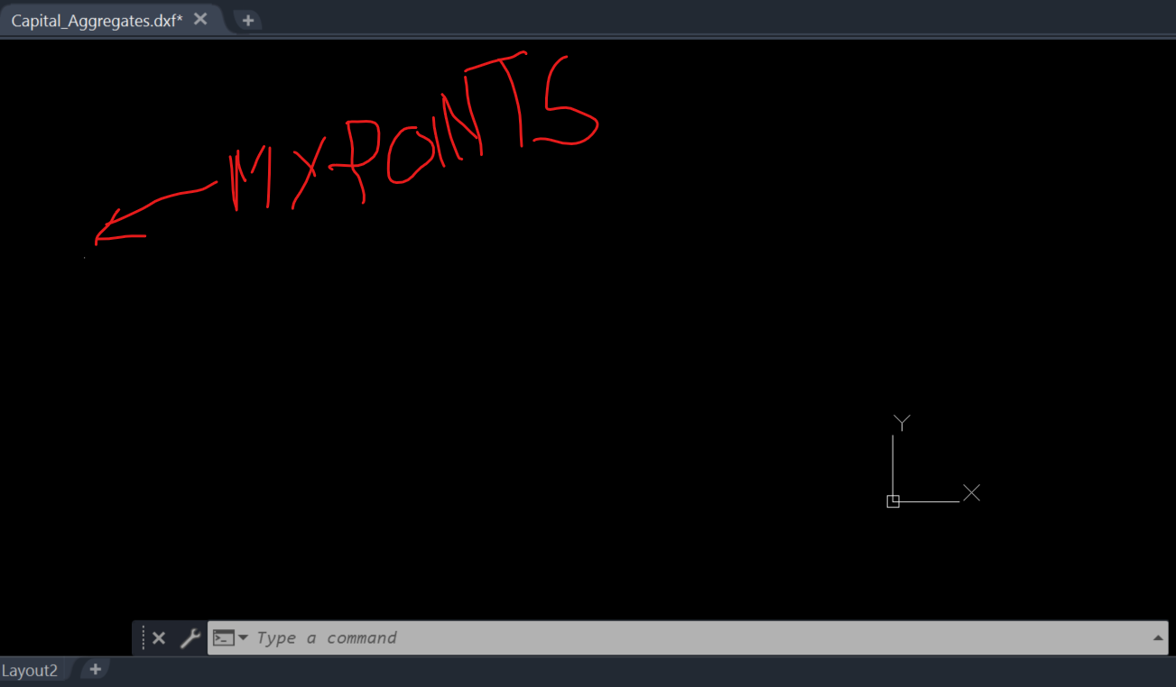
Ok, I used MyGeodata Converter and it worked great, the points show up on the map right where they should be. this tells me my data is good. however, I am still having problems getting the points to scale correctly. when I open the DXF the points are still a fraction of an inch apart rather than feet apart like they should be. I really am stumped here because there is nowhere to set the units for the DXF because it was created by MyGeodata. it should already have the correct units designated.
You have negative coordinates in CAD? That’s one problem and is probably the results of bringing geodetic coordinates into a projected drawing without having any transformation involved. The data looks correct in MyGeodata? Have you tried QGIS? The scale escapes me because it’s usually 12x, 3.28084x or the inverse. There’s also iFT versus UsFt but it would still be on the positive side. Scale factors are usually only in the ten or hundred thousandth and that would cause what you are seeing here.
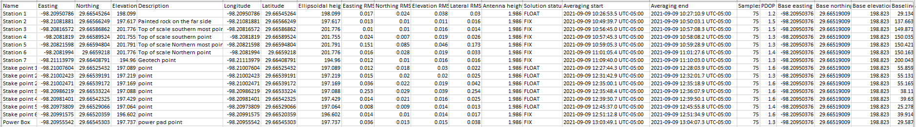
I would love to share and I’ve tried to upload the CSV file but I get this “Sorry, the file you are trying to upload is not authorized (authorized extensions: jpg, jpeg, png, gif, svg, obs, nav, pos, bin, log, tlog, zip, apk, pdf)”. I have attached a PDF of it but what’s the best way to share it?
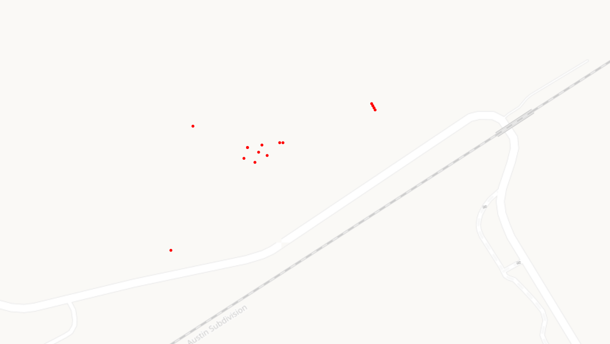
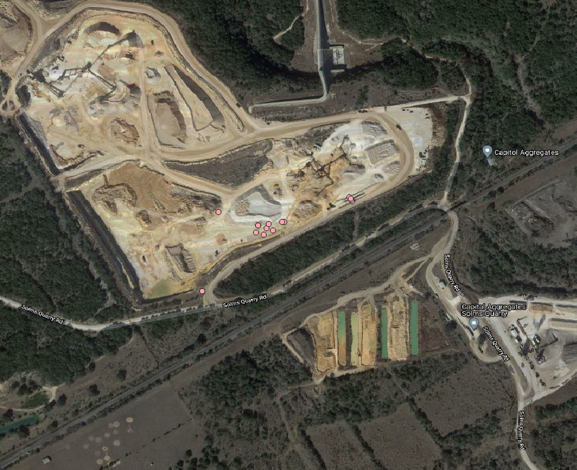
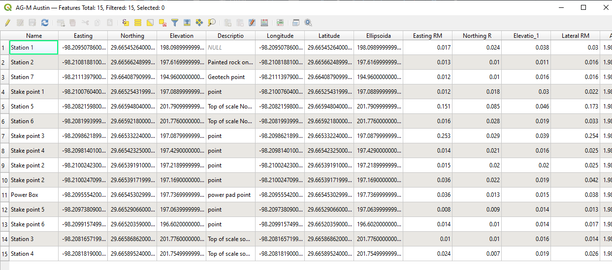
Are these your points? This was done in QGIS in about 30 seconds. It’s confusing at first but once you start to get used to it you will find it very powerful at converting all kinds of geo data.
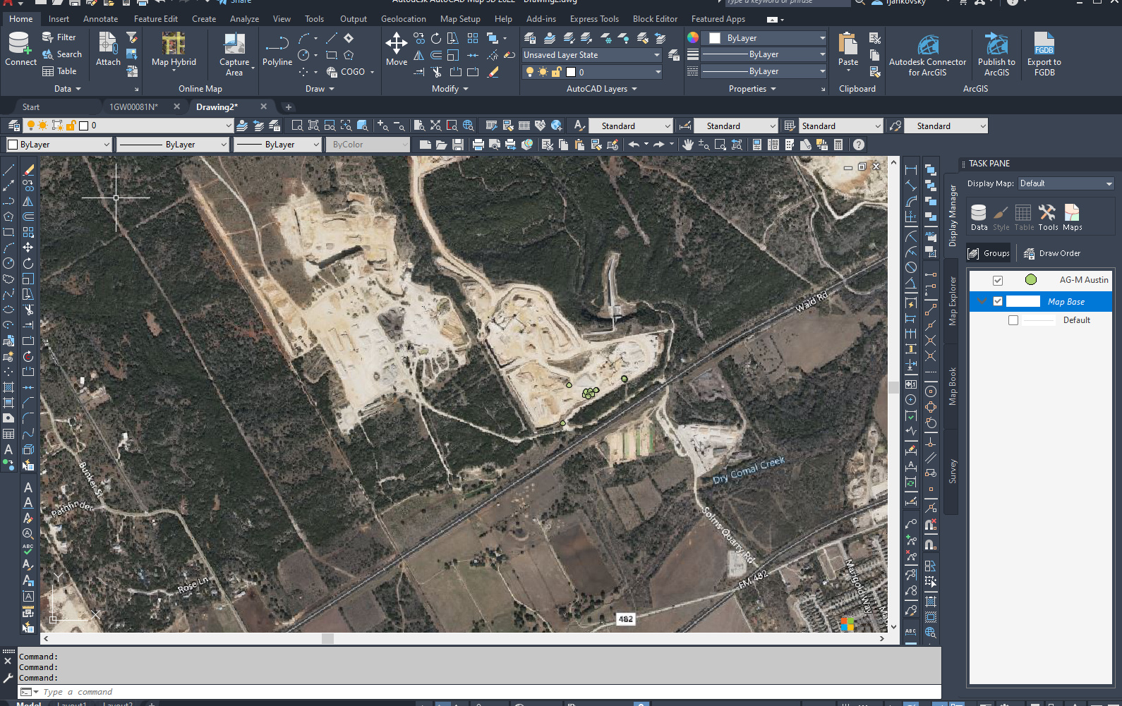
Here’s your points in Autocad Map3D. If you want to work in the Autodesk environment download a free trial and I’ll give you the quick tutorial on setting up your CRS so that you can do this.
Edit: If you have a licensed version of Autocad , Map3D is part of the suite of software that is included so you don’t need a trial, you’ve already paid for it.
Here is a shapefile. You can drag and drop the .shp file into QGIS and you will find your points. You can also open the table in QGIS for the shapefile