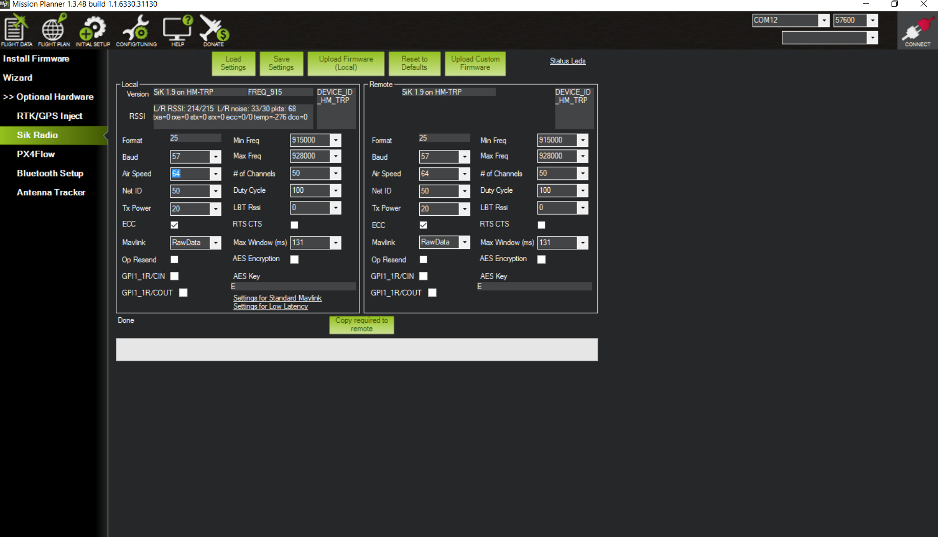
I have a pair of Reach units that I am attempting to set-up as an RTK system to use on a rover. After some difficulty I have been able to connect to each device via wifi and to configure them (following the documentation). As they should, both devices connected to the server and downloaded the latest version of ReachView (2.5.2 I believe). I want to use a pair of 3DR radios (connected to the UART) to send corrections form the base to the rover. I used MissionPlanner to assign a unique NetID to the radios and to set the baud rate (57 which I assume to mean 57600).
I also checked the baud rate of the associated COM port for each radio - it too was set to 57600. When I power up the base and the rover I can see that each is seeing satellites and calculating a position (though not corrected). The bar chart on the status page shows satellites (w/ varying SNRs) but there is no evidence of grey bars on the rover’s display indicating base corrections are not being received. The LEDs on the radios are solid green and flickering red (at a fairly high rate but not apparently at a fixed rate). If I look at the logging tab, the base correction log (on the base Reach) is increasing suggesting that correction messages are being generated. This all suggests to me that the problem lies in the radio link. I believe the radios are working when I used MissionPlanner to change the NetID, the radios’ green LEDs flickered and then went solid green. I interpret this (based upon Sik radio documentation) to indicate they were looking for another radio when they were powered up (green flashing LED) and when they found each other the LED switched to solid green.
I would appreciate any constructive suggestions. By the way, to honor the wiring information in the Reach documentation, I had to switch the RX/TX wires on the DF13 cable supplied with the Reach units. Is there a reason why they are delivered with the incorrect wiring connection?
Here it is. I wasn’t sure if I needed to change the Air-Speed setting (I took the default). I did change the Mavlink setting from the default value (Mavlink) to Raw Data. I didn’t appear to impact anything.
I have a USB-serial cable. I could possible use the DF13 - 6P-to-Jumper cable supplied with the Reach to connect to the serial connector on that cable. What would I do with that, use a terminal emulator to “see” what is broadcast from the Reach’s UART?
The green LED is on (solid) on both the radios (rover and base). The red LED next to the green LED is flickering on both units. These radios have additional red LEDs near the connections. When I tested a pair of these radios with a terminal emulation program (Termite 3.3), these lights flickered when I transmitted data from one radio to the other (successfully). I don’t recall seeing these LEDs flashing when the radios are attached to the Reach units. I will try to test the communication between the radios connected to the Reach units with the terminal emulator.
I will test the continuity of the cables with a meter.
If i can figure out a way to power the Reach units through either of the UARTS, I will see if I can use the USB connection on the radios to broadcast corrections from the base to the rover.
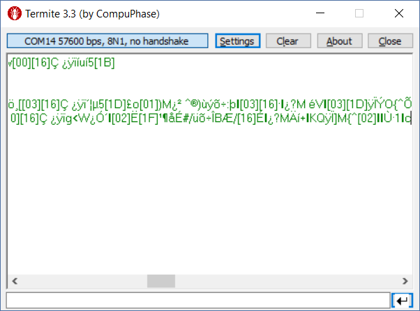
I hooked up a serial-USB cable to the Base Reach (instead of the radio). After setting the baud rate on the cable to the same as that specified in ReachView (57600) I saw the following in the terminal window connected to this output
So the Reach is outputting something, I don’t know if its supposed to be readable. For “fun” I changed the baud rate on my USB-serial cable. Still saw strings of gibberish so I don’t know if that means anything is wrong.
I did test the pair of radios connected to the Reach units. As with the other pair of 3DR radios I previously tested, I was able to send text strings between the two radios using a terminal emulating program. I was able to confirm that when transmitting a red LED flashed on the lower right side of the radio, when it receives a message a red LED flashes on the left side of the base. These LEDs are seperate from the red and green ones located near the middle of the board.
I was able to test continuity on both wiring harnesses - neither appears to have a broken wire.
Thank you for your patience. This getting really deep, everything seems totally fine.
RTCM format is binary and thus not readable. However, I would suggest trying a setup like this:
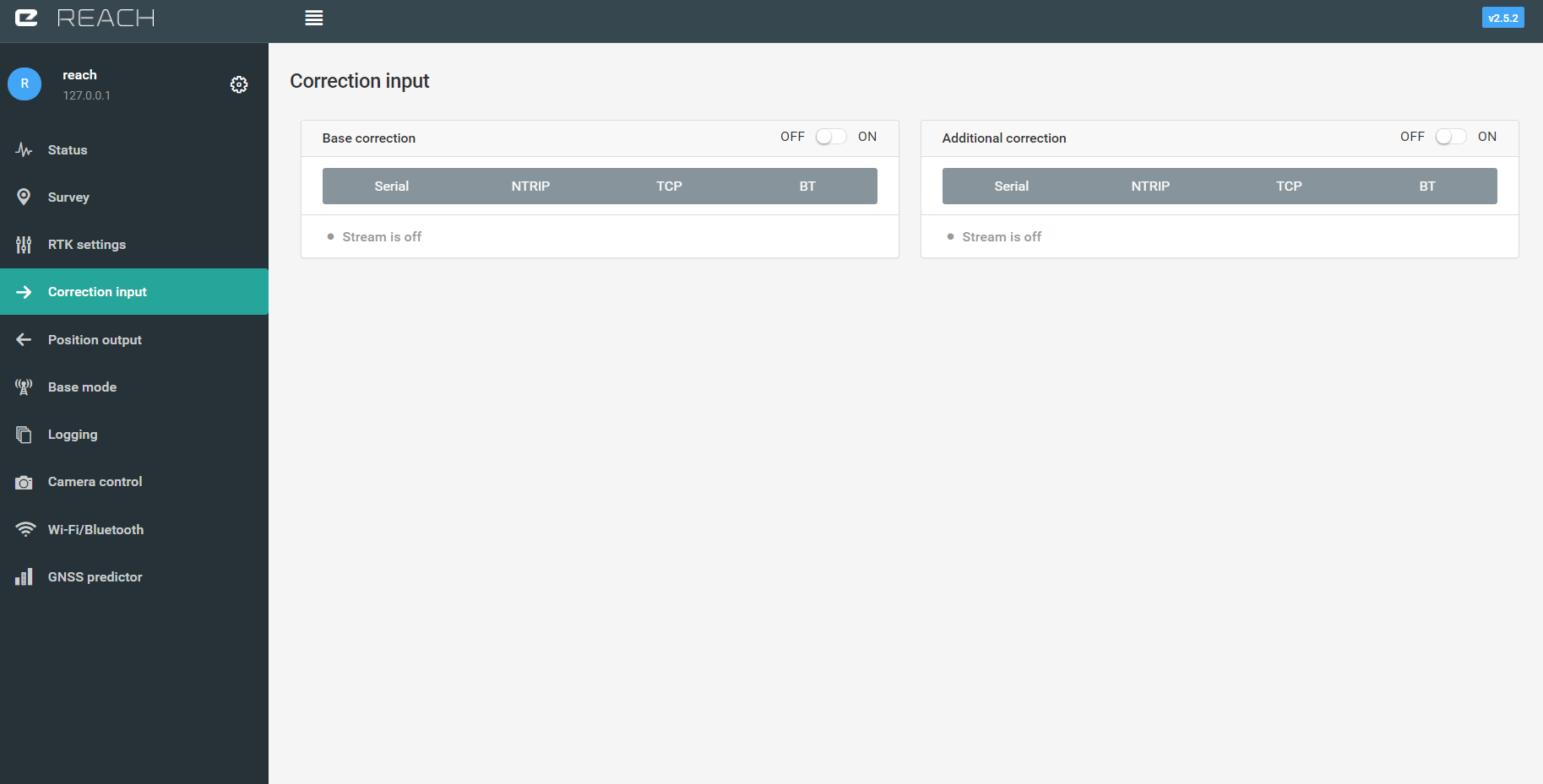
Connect one of the radios to the base reach. Instead of outputting base corrections, configure position output with NMEA format to the UART port
Connect the second radio to your PC, try to read the output with Termite. NMEA is text-based and will be sent even with no solution. Try this and see if it works.
If everything is fine, swap the Reach modules and try the same thing with the second one. With this we will make sure the hardware is good.
I would also like to see a photo, or better a small video, of your setup with the radio blinking lights.
I will try what you suggest - good idea! I will also see what I can do about the video/photo you ask for.
One other thing you might want to know. I have had problems connecting these devices to my local wifi network. I was able to connect then to a smartphone’s hotspot. This allowed me to have each connect to a server and download the latest version of ReachView (they are both running v.2.5.2). Since then I connect to them using their hotspots. I have had NO problem connecting to them and changing any ReachView settings, I can see that satellite SNRs are changing, so I don’t think this has anything to do with my problems. It does mean I can’t try to send my base station corrections via wifi.
I have to take care of another (unrelated) issue this morning, so I won’t be able to give you an update for a couple of hours. I don’t know where you are, but I am in the Central Time Zone in the US. I really hope we can resolve this today before the weekend.
The tests you suggested were positive (I could see valid data arriving at the 2nd radio connected to my PC) for both Reach units.
I shot some video but they were too large to send you.
Reachview seems to be a little fussy - if position, correction, inputs/outputs are mistakenly on at the same time it appears you can get hung up (the spinning wheel that continues to spin). The only soloution appears to reboot the Reach if that occurs.
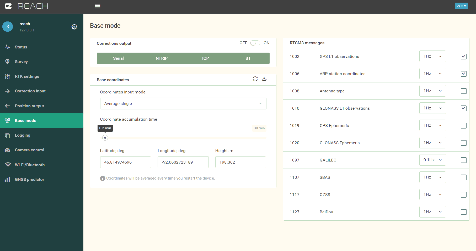
How should the RTK settings positioning mode be set for the base station, single or static? Does it matter?
You mean they are all configured to the same port? I’ll check that.[quote=“nijoe, post:12, topic:6085”]
How should the RTK settings positioning mode be set for the base station, single or static? Does it matter?
[/quote]
No, the last thing I did was re-try the normal setup. Nothing.
Do you think there’s any reason to think the fact that they are not on a common wifi network that this could be a problem. I want to remind you that I have had problems connecting to my network so I temporarily connected them to a smartphone’s hotspot (not my phone - its not smart!) so I could access the server and install the latest version of ReachView on them. Once I did that I have been connecting to the units via their hotspot. This would be a problem if I wanted to use TCP/IP to send corrections from the base to the rover, but not in principal if I have working radios! They appear to be working and communicating - at least that’s what the NMEA tests suggested earlier today.
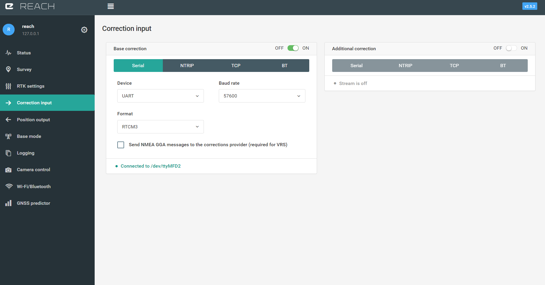
On the rovers correction input tab, there is a green plaque, that says uart is connected. Is it clickable when everything is set up? If everything is good, it will unwrap and show rtcm message count.
Update. Today I tried a couple of things to try and solve the problem. Neither worked! This is what I did
I clipped extra connections on the supplied UART connector so that the only connections are 5V, GRD, TX, and RX
Based on a user’s early post to the forum, I slowed the baud rate to 9600 - no change!
I have a couple of observations questions.
On the Reachview status tab, the satellite bar chart shows the number of satellites seen by the device. For both Reach units only the “Rover” sees any satellites, in other words the base Reach is seeing satellites but reports on this page as if its a Rover. Is this what it should do?
I have looked at the Logging tab. For both the base and rover Reach logging is turned on for raw data (ubx), position (erb), base correction (rtcm3), and additional correction (rtcm3). It appears that on the base station, ONLY raw data, and position logs are actually getting anything, the other two logs don’t accumulate any information (according to what I have read in the docs, I don’t expect the additional corrections log to get anything).
Interestingly on the rover, raw data, position AND base correction logs are collecting something. The base correction file is pretty small. I have downloaded these and have attached them
While I wait for some suggestions I have managed to get both Rover and Base on a common wifi network (a cellphone’s hotspot). The radio link still isn’t working BUT I have been able to use the TCP correction mode to get corrections from the base to the rover. Although the solution hasn’t fixed yet it is now using the base corrections broadcast over the network. Too bad I won’t have a wifi network in the field!
I am surprised that ReachView on both units reports that I am up-to-date even though it shows I am running 2.5.2-r0 - I believe that 2.5.3 has been released. Any idea why I am not downloading the latest version? I am wildly hoping that this upgrade might solve my problem.
I reset both Reach units to default settings hoping that that might catch the error I must have made somewhere when I configured them - it doesn’t appear to have solved the serial connection problem that I am having.
Does it matter if BOTH radios are connected to a UART? Reading earlier posts to the forum it appears that at one time one radio should be attached to a UART and the other radio should be attached to the Reach’s USB. Is this still true? Currently both radios are connected to the Reach UART (one on the Base, the other on the Rover Reach).