I’m doing aerial mapping as a freelancer and to support our ecological research. I’m always interested into the accuracy which can be reached with the Reach modules and photogrammetry as well as best practice workflows to achieve the highest accuracy.
Since I think the practical experience presented in this forum is a valuable source I want to share my personal experience with you. If you have suggestions how I can improve or questions etc. you are very welcome to contribute to this topic.
My first report is about the mapping of 450 ha rewetted peatland which I did in autumn 2018. My base was installed 3 km way from the mapping area. The position of the base was determined by using an topographic point (accuracy of the point ~10 mm) some 100 m away.
I’m mapping with a custom build hexacopter based on Arducopter. The take-off weight is 2.3 kg and the flight time is about 28 min in summertime and 18 min in wintertime (I use significantly less than 80% of the battery capacity). The images are taken with a Sony RX100M2 which is mounted on a 2 axis gimbal and connected to a Reach module. I did fly missions from several different starting points (really hard work carry 75 kg of stuff through the peatland) with an overlap of 80%/60% (front/side) and a speed of 8m/s.
In order to get the camera positions I did post processing with RTKlib (without additional data such as clock file etc.). and lever arm correction and transformation into ETRS89 / UTM zone 33 and DHHN2016 (orthometric) height with a custom python script. The photogrammetry part was done with Agisoft Metashape (processing settings high) and exported with a resolution of 7 cm/px.
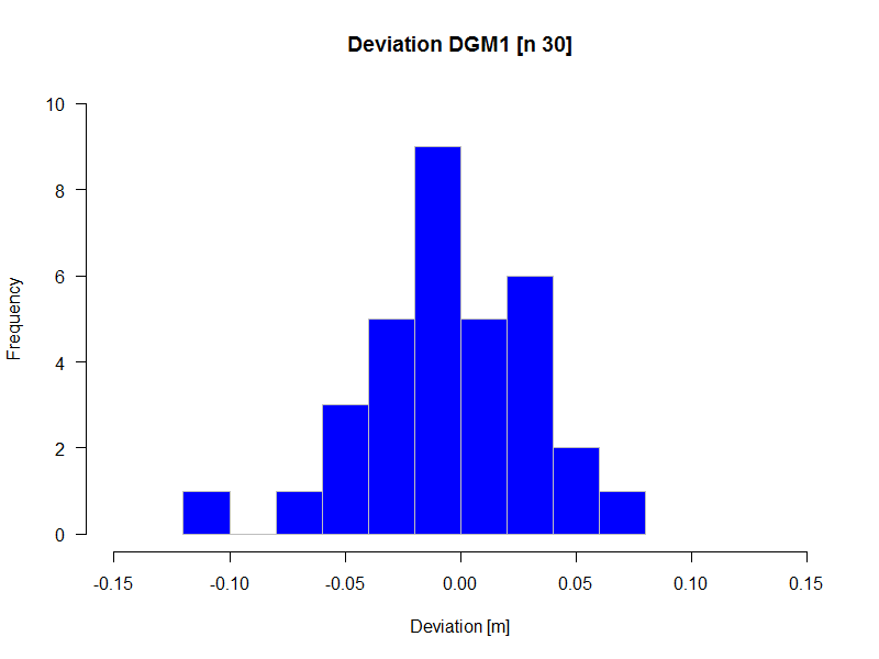
To get an impression of the height accuracy of the produced dsm I did compare it to the official dtm which has a resolution of 1 m and an accuracy better than 0.15 m. I did that in QGis and did a more or less biased sampling by picking 30 points with bare ground from all over the dsm (s. fig. below).
The standard deviation was 3.7 cm. I think the result is quite satisfying (since the deviation is a cumulated error from base position measurement, camera position measurement and photogrammetry processing) and could be even better when using ground control points, flying with more overlap and slower speed.
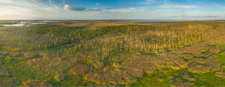
I could post a panoramas of the area or the aerial map/dsm. I’m always missing to make pictures of me working. No time for that… . I try it next time. I have also some other sites which are interesting examples and where I can compare to GCPs measured with a Trimbel dual frequency receiver.
BTW: it would be great if you could enable the possibility to format the images to float left/right.
I can do that, I just have to update the viewer.
Is it possible to integrate iframes into the post, guess that would be the most user friendly solution?
This is a short report about the results of a revist of some ground control points (gcps) I placed 2 weeks earlier.The distance to my base (a Reach module) was between 200 and 400 m. The observation period during the first survey was 40 s which was to short and resulted in a fix for only 19 of the 24 points.
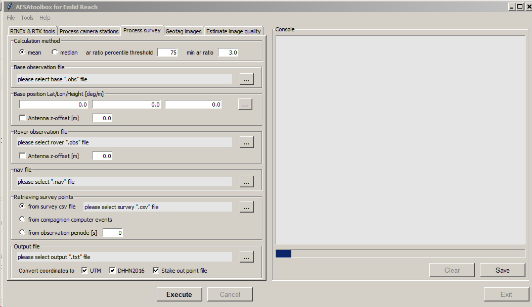
I calculated the position of the gcps with the help of a python script (fig. 1) which reads the observation period of each point from the survey csv file (exported from Reach). The script then calls rnx2rtkp.exe (the command line version of RTKpost) to calculate a static solution for each point. From the resulting solutions it averages the ones with the best ar ratio to get the final position.
During the revisit I was walking to the gcps with the help of the stake out feature. The corrections where transfered via a wifi network and a repeater in the field which made it possible to get the corrections from the base station without problems (I guess it works for more than 600 m in an open field). I prefere a wifi network now because than I do not have to switch settings when using the base station for my drone and we can work with two rovers at the same time.
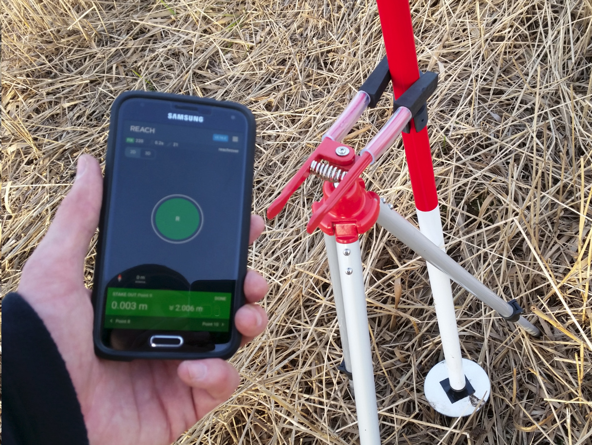
Some of the gcps survived the crossing of a mowing machine and when placing the rover on top of those gcps and controlling the position with the stake out feature the result was very accurate (fig. 2, z deviation 5 mm). I will add the results of the postprocessing later on.
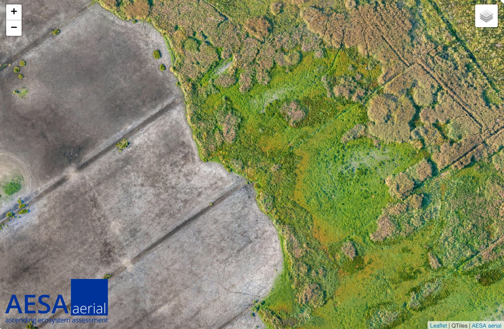
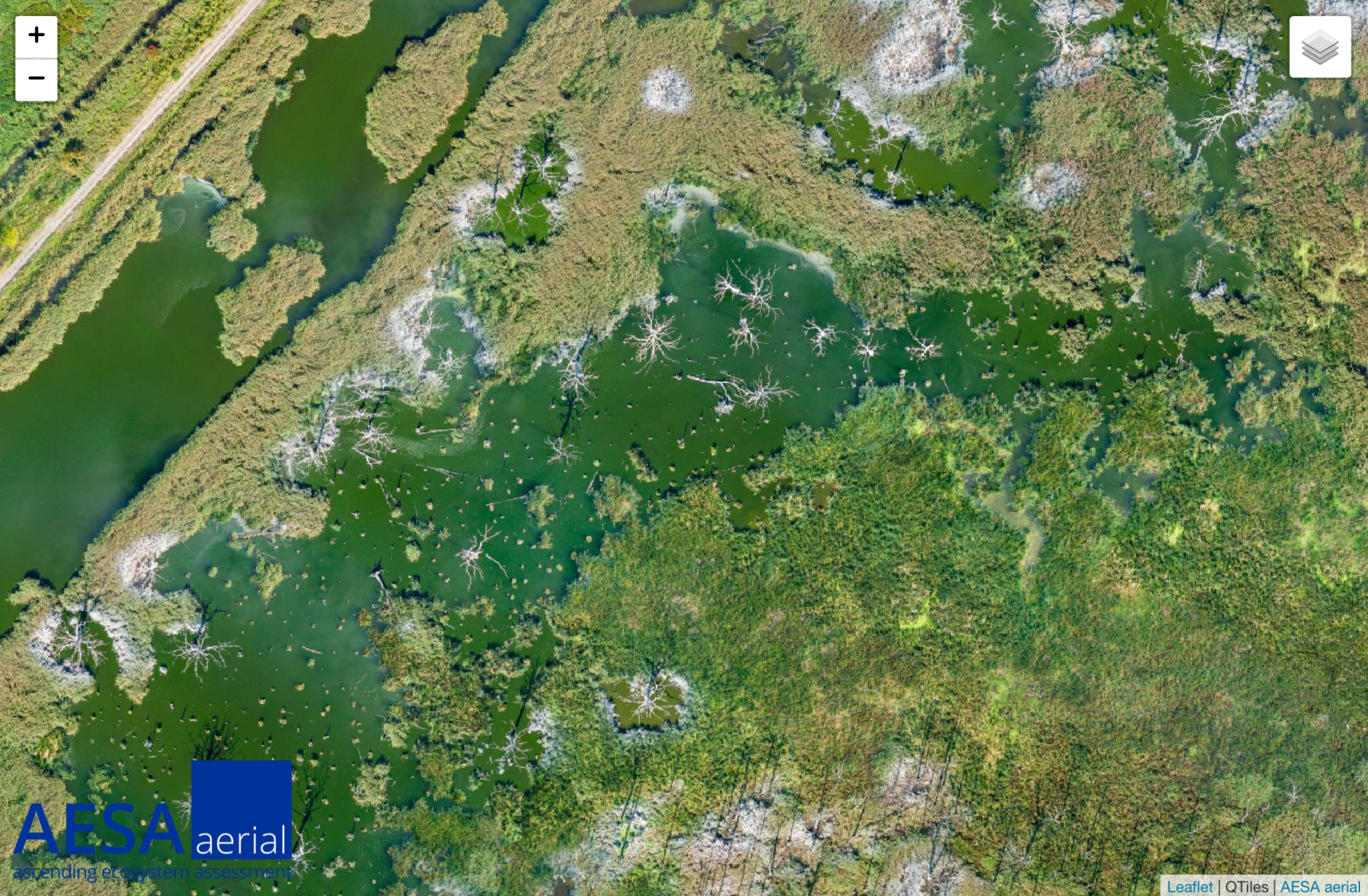
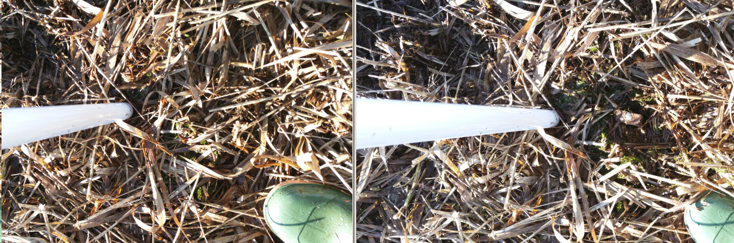
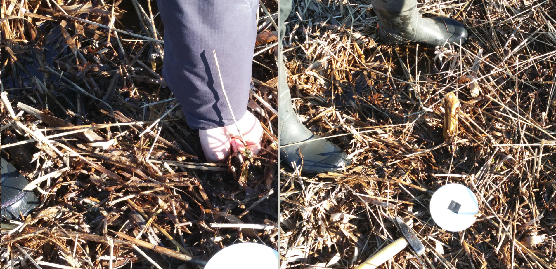
For those points which where pushed into the ground by the mowing machin the stake out feature helped to recover all points where a fix could be calculated. It was not possible to find those points without the help of Reach (example fig. 3 & 4). E.g. we searched for the base point marker for more than 30 min. and didn’t find it. After setting up the base on our backup base point marker I did find the original base point marker immediately. We could only find one of five points where no fix could be calculated. This point had more than 1 m offset.
I guess Reach can easily replace our Makers & Schonstedt Magnetic Locator which we normally use (with an additional GPS) to find our permant observation plots.
Nice work, kudos! Have you shared any of the panos yet? You might try Kuula if you need a good sharing platform. I used it for all of our panos (including terrestrial) before DroneDeploy finalized their in UI viewing capability.
A question from an earlier post… Why did you use a point so far away? If you are using GCP’s you are already localized? Or, did you use “GCP’s” more like checkpoints?
With GCP I mean a point which I use to verify my results. What is the correct name for that?
I do not understand the rest of the question. Could you please give more details?
I would call that a simple checkpoint. The true nature of a GCP is a highly visual target that can be used in the photogrammetry process to localize the data and more accurately perform camera location adjustments. Now that I am using PPK I have been able to go from 10-15 per project to 5 or 6. PPK or RTK alone will never truly tie your data to the actual ground site control.