


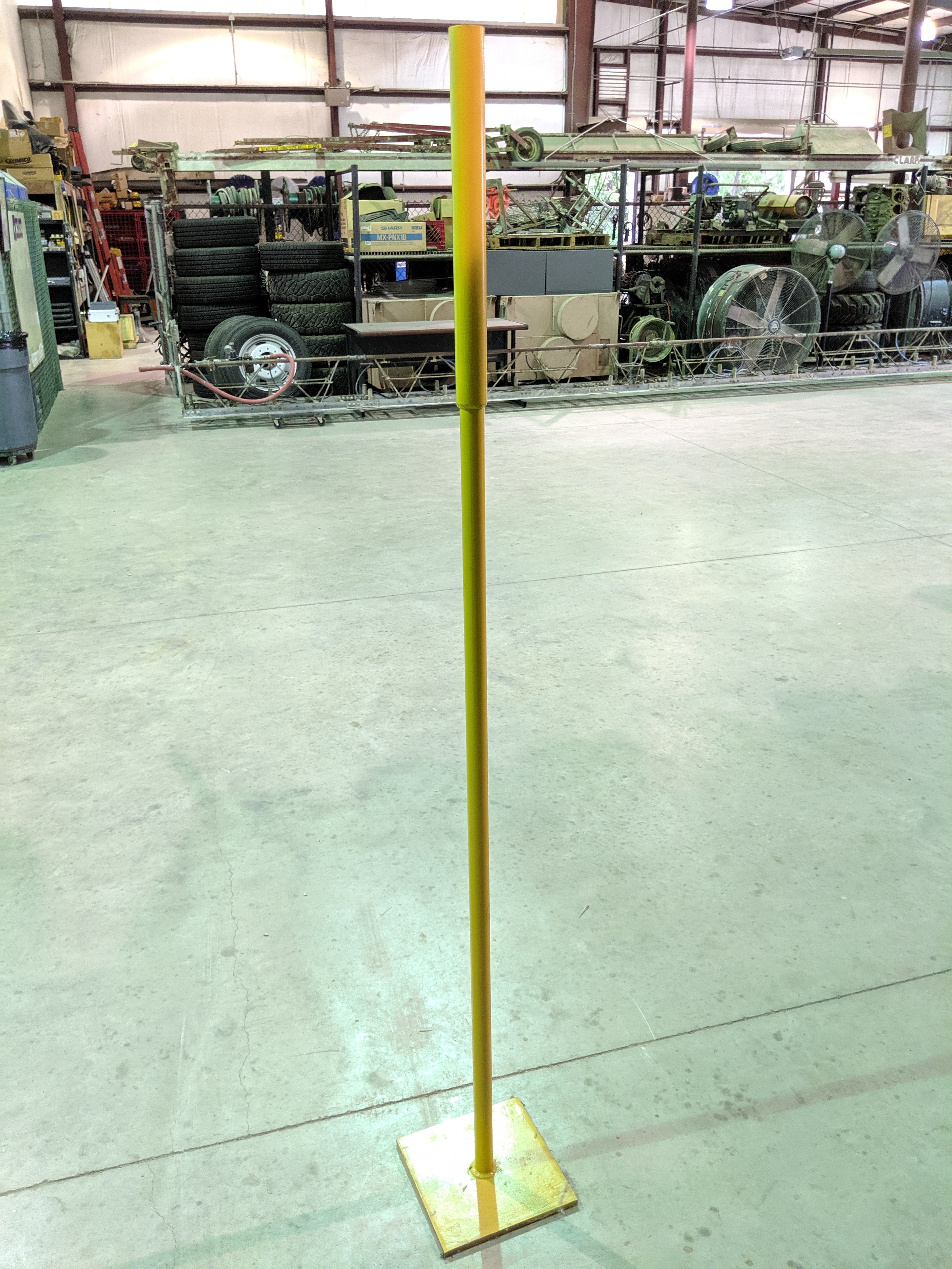
Almost something similar to, but more portable than our base poles. Ours are metal and the top section of pipe is the perfect size to fit the brass “pucks” that screw on to the bottom of the base, but yours could be PVC. You just need a decent weight at the bottom.
1 Like
Michael,
Pix4D and DroneDeploy are free, but they do not have a linear mission planning routine for free.
DroneDeploy does. It’s in the App Market. I have been an Enterprise customer for almost 3 years so any questions are welcome. I did login with my personal free account to verify…

Here’s what I use sometimes, but it may not be tall enough for you…
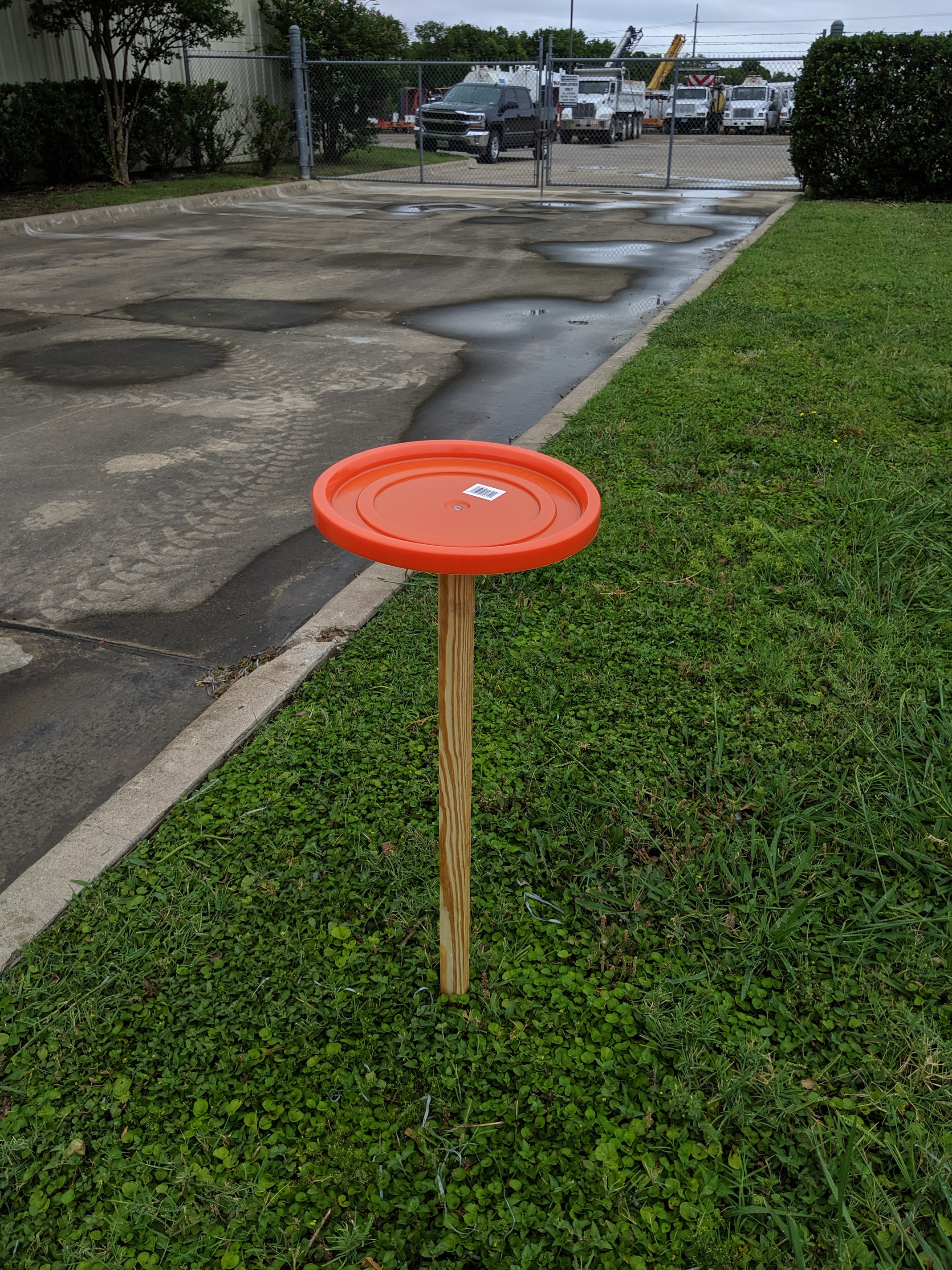
*Edit. This was a quick example. I typically put a little bigger screw and washers on either side. The washer on the top also serves as a focal point when tagging the GCP’s.
3 Likes
Thanks for the suggestions on the apps. My corridor has some nice straight legs, so mapping it with a simple rectangle is trivial.
What seem to not be trivial is placing 100% correctly.
I have tried planning it by using terrainfeatures, but as a have a georeferenced map of the pipeline, I would like to use that.
But none of the apps seem to support importing of custom maps?
I must recant my previous statement about DroneDeploy and the free linear flight. Once I actually enabled it and toggled the option it told me I need a Business account. I am working with them on this and hope to get them to release it to all accounts.
Can you PM me some of the data? I’d like to take a look at what we can use to extract what you need.
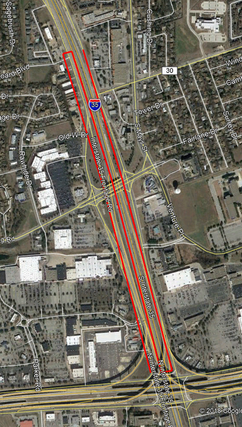
I got a scanned map of the area, that I then georeferenced in QGIS. Through that, I can place the corridor within 0.5-1 meter on the ground without difficulties.
My main issue is how to plan the waypoint flight from either coordinates or the georeferenced map.
I have made a waypoint mission already, where I tried to follow the corridor by terrain features, but that seems to a very inexact science, where I easily hit 10 meter errors.
The more I think about what you are trying to do the more I want to suggest getting Litchi. It is the most versatile program out there. Maybe not the most intuitive at first and it does not have the standard lawnmower pattern, but there are plenty that do that. Just create a KML path in QGIS or Google Earth and import into the flylitchi hub. I like to do final editing on the tablet because the app lets you do batch actions that for some intelligent reason  is not on the desktop browser.
2 Likes
Here’s one of the crazier maps that I have done in Litchi. Solely for the fact of terrain following. Other programs will not do this with a change in direction like I have. The purposes was to run parallel with the major slope so that the drone would maintain a better constant altitude. Running into the slope can literally be bad, but I have also noticed that it does not follow the terrain as smoothly. Litchi does max out at 99 waypoints…
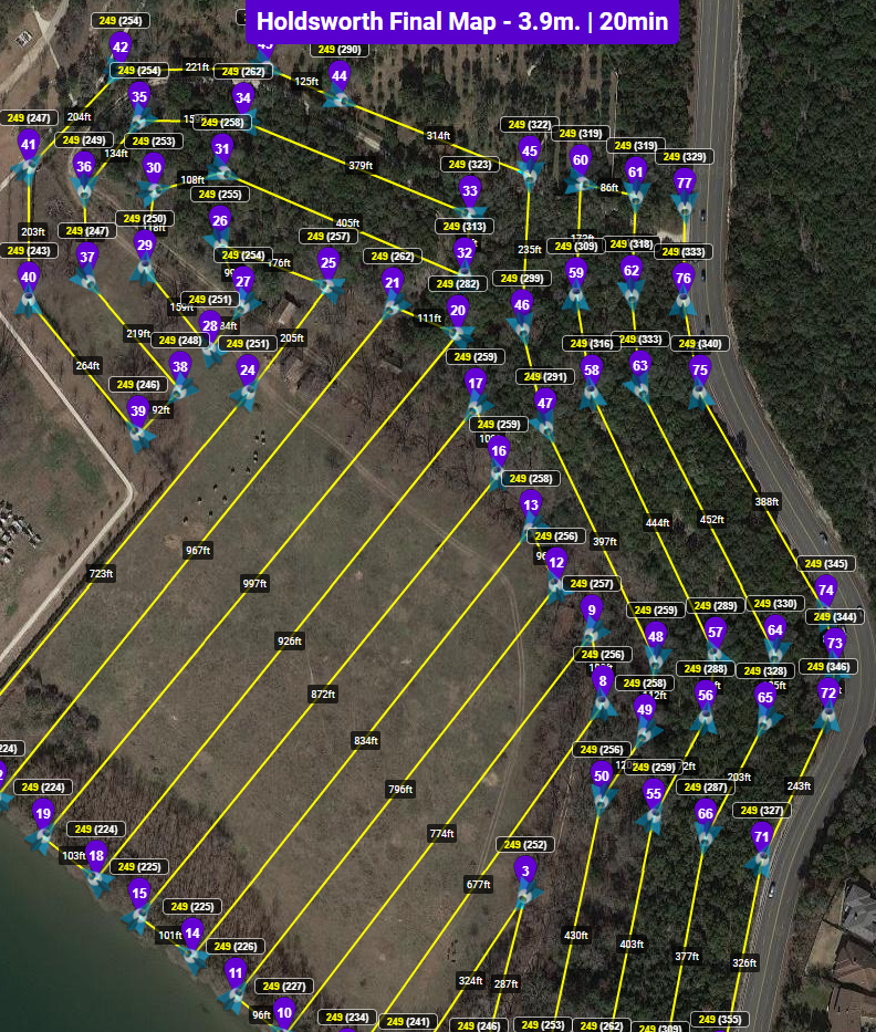
Consistent detail across the entire 160ft elevation change.
Profile
3 Likes
I have bought Litchi years ago and love it, but I can’t work out how do continous triggering, which hinders the use for mapping?
Camera settings under the shutter button
Photo Settings
Photo Mode to Interval
I normally run about 250ft so I use about 100-120ft width on the lanes. Use 2 seconds at about 20mph to get 75% front lap.
Thanks, I’ll give it a try later!
1 Like
Just found that DJI GS Pro can import a shape-file ![]() That might solve it!
That might solve it!
1 Like
Luke’s tips are solid. I will just add this, I am assuming you will be using multiple batteries/flights. Place your controls however you decide too in the overlap of the flights. This is especially true in difficult, homogenous terrain. In experience with Pix4D each flight presents possibility of multiple blocks in the reconstruction. In homogenous terrain you have difficulty in finding tie points. I don’t know about other softwares handling of blocks but with too few tie points in the overlap areas the project will not merge into single block. When they don’t merge I have to go in add manual tie points in effort to force the blocks to merge together and processing to finish.
I know better now after mapping 2500 acres of pure golden California grassland in single day with P4P. I had to use cow patties as my manual tie points to force the model into single block. The blocks were formed generally for each home point. Each home point I could get four flights in. I had about 4-5 different home points on the whole site.
My suggestion is to focus on a quality flight plan with as much overlap as you can afford to milk out as many tie points as possible. If multiple flights, overlap the separate flight paths considerably and put your GCPs right in the overlap. I would definitely do two in the areas of overlap and just stagger between if even needed. More is always better in homogenous terrain. Minimize number of home points even with GCPs. If you can do the whole project from one spot, kudos. If you can afford too hit it again in a cross grid pattern just to be sure. Even doing a cross grid sometimes doesn’t get me the tie points needed.
Oh and lighting, photo quality, is huge factor if not the most important factor in homogenous terrain. I fly now my grasslands during the golden hours. This gives me greater contrast and clarity in my imagery whereas at solar noon I would get absolutely blown out by Bi-Directional Reflectance Distribution Function (BRDF):
3 Likes
BRDF have not been a problem so far, but then again, I seldom shoot at high noon and only do non-ortho if I do volume measurements 
Thanks for all the heads up!
With regards to image quality, I am split between flying my own P4P and a M600 with a Phase One iXM 100 with a 35 mm lens. Doesn’t sound like a tough choice IQ wise, and it isn’t, but using having to fly the mission VLOS, the legs need to be split in 4 different legs. That means setup and pack down time quite a bit longer than the Phantom (5 min vs 20 min x 4). Flighttime is roughly the same, and the M600 + IXM can fly faster as the capture interval is shorter, and the camera uses a Global ahutter…
Oh all the choices
1 Like
I would tell the farmer that he will have a small area of crops flattened around each GCP.
GCP should be placed on a reasonably level area not close to sudden level changes, large rocks, fences etc.
Best thing you can do is use a old carpet tile and spray a chequer pattern on it. So it has 2x2 alternating squares.
Place in the desired location and flatten down the crops approx 2m beyond the GCP. Use a length of timber and flatten it down.
The cost of the lost crop versus a bad survey solution is what you need to consider.
1 Like
Thanks for the advice!
But wouldn’t flattening out a patch of crop do exactly what should be avoided, the sharp/sudden elevation changes?
You would essentially have floating GCP.
Obviously you will have vegetation which will effect the accuracy of the results. But i would strongly reccomend using proven methodologies.
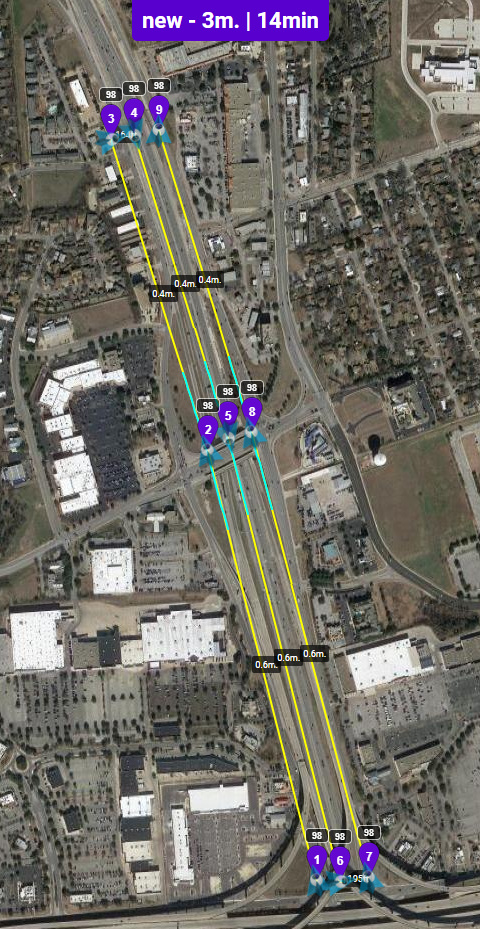
Just a zig zag pattern would not be my ideal placement either. I would want to place at a minimum one GCP per 100m along the alignment of the proposed pipeline. Then also place additional control to the sides at the alternating chainages.
Also there will be damage to the crops along this route and i presume there are access paths which you could utilise.
Poor GCP placement is the main cause of poor photogrammetric models.
This project is more suited to a RTK / PPK fixed wing system such as the Topcon Sirius or Ebee.
1 Like
Running a straight line of GCP’s is not a good idea and has been proven to tilt around that line on many road projects that we have done. Again, the zig-zag pattern was recommended when using PPK in addition. He is not so no the zig-zag is not preferred. Two GCP’s perpendicular to the centerline offset just inside the area of interest space about 150-200m down the center line is what you want. They can be closer if you like, but that is your efficiency vs. absolute accuracy call. What’s the balance?