3DroneMapping completes PPK trials

3DroneMapping has been testing a PPK system for the past year to itegrate into our daily workflow. The point of PPK (or Post Processing Kinematic) is not just to improve internal photogrammetric model orientations, but also is general recognised as a way of undertaking full scale surveys at the same accuracy but without having to place time consuming ground control points. 3DroneMapping setup a calibration site to test the claims made by the manufacturers and ultimately for our own quality assurance that what we publish is indeed right the first and only time.

Ground control points traditionally have become a sore topic with RPAS aerial surveyors as they take time to construct, survey and verify. These points are needed in a much greater density than tradition aerial survey methods, due to the non metric cameras often used in RPAS. Locations where the terrain changes rapidly, homogenous surfaces, and densely vegetated areas all require a higher density of control points to assist the photogrammetric software to locate accurate ties points and stop the model from deviating. Undertaking a photogrammetric survey without control, can lead to disastrous results, as outlined in a previous article, “GROUND CONTROL VS NO CONTROL”

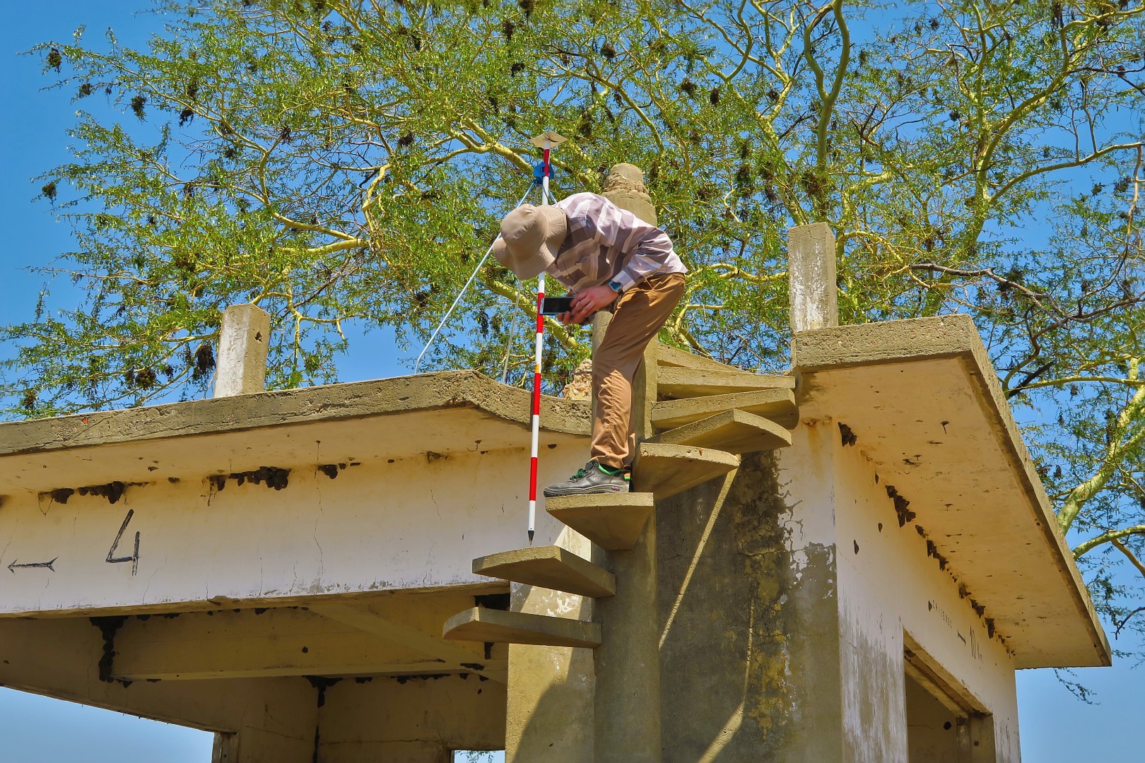
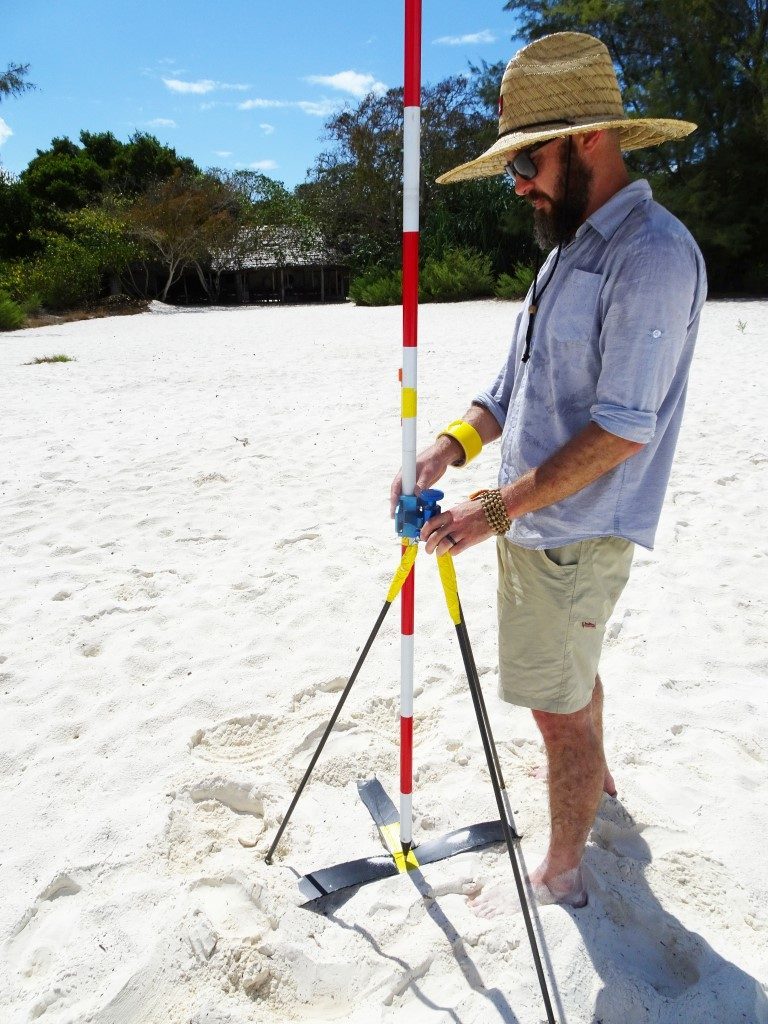
There are a number of issues with placing and surveying control points. The obvious one being that another piece of survey equipment is needed to accurately record the positions. This comes at a great cost as survey grade GPS systems can run into tens of thousands of dollars. Then the areas for the control need to be identified. These areas are often located at the fringes of the site to be surveyed as well as in the center. This means that the site needs to be traversed (often on foot) to place marks and survey them. In some cases it can take a few days to complete the marking for fairly small sites due to the terrain, vegetation, etc. Control points are also not permanent. They often go missing due to weather, theft for vandalism and cause problem for the surveyor back in the office when the surveyed points are not visible on the imagery.

Another problem with using control only for surveys using low level photogrammetry is that the consumer grade cameras used are not metric and are prone to distortion. While control can eliminate this to an extent, it is the areas between the control points that often are forced to fit alignment. This can lead to errors especially regarding heights.

Emlid has produced and excellent L1 only reciever that is sure to revolutionise the Small Unmanned Aircraft photogrammetry sector. Coupled to a decent camera with a good lense and sync cable, the setup allows you to undertake surveys to mean accuracies of less than 10cm. All that is required is a base and a rover (2 devices) that log the data for you in an easy to operate webviewer. No need for external comminication radios, or fancy antennas, only a steady 5v supply like a battery bank.

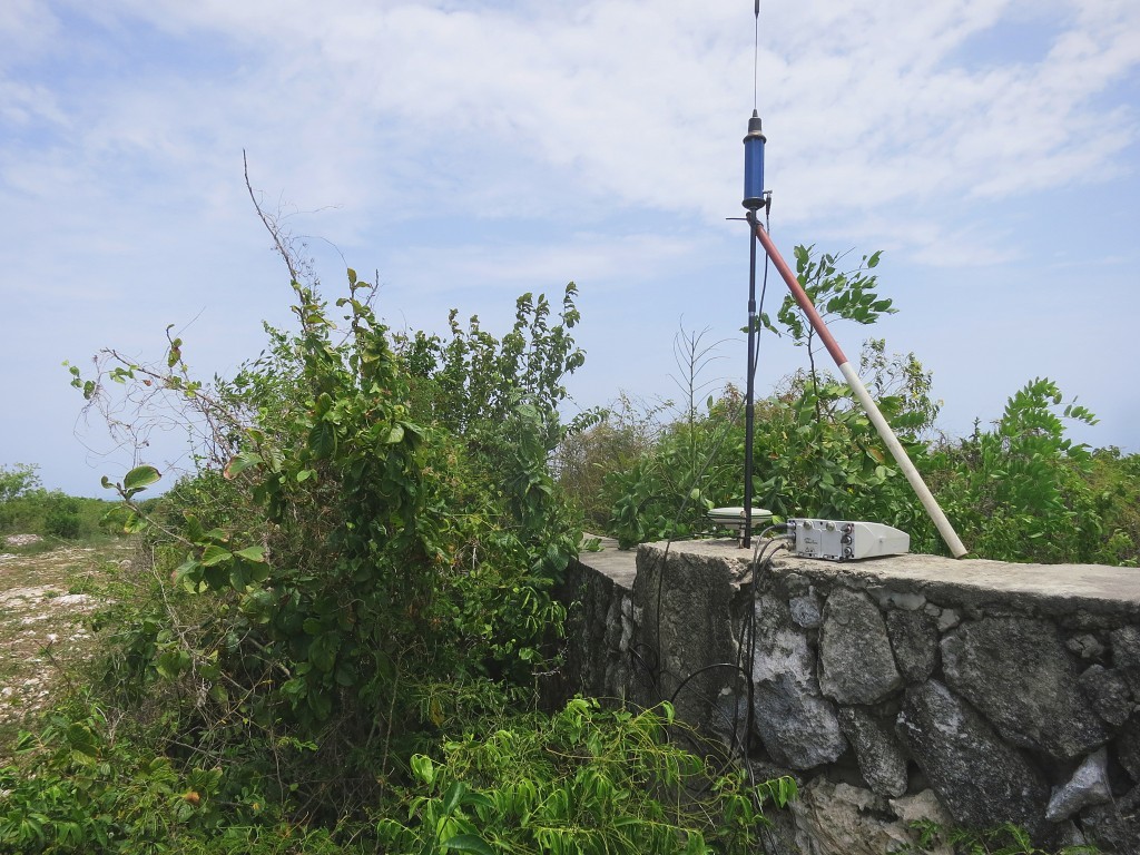
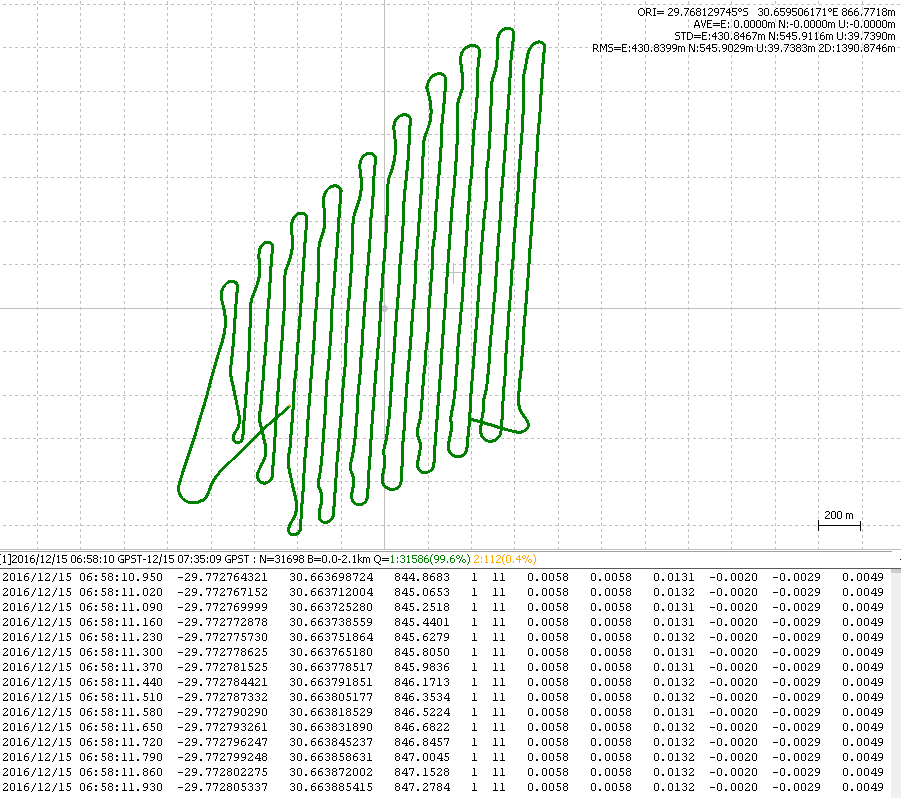
PPK is setup to have an accurate onboard GPS system that records a high frequency measurement tracklog of an RPAS flight. The system notes every time the camera takes an image and logs it. Another GPS is setup on the ground to record satellite information during the flight. Using a fork of RTKLib, Emlid has developed their own flavour of this powerful piece of software that takes into consideration each time the shutter is trigger and records the position of that event. The timing of such an event is crucial, as a few milliseconds delay can translate to a few meters when operating at speed. The software compares the relative satellite positions between the devices, resulting are very accurate coordinates for each image captured.

The photogrammetric model generated from using PPK enhanced images gives a much more consistent and accurate rendering of the terrain. Tie points have a much greater certainty of intersection, speeding up the matching processes. This reduction in uncertainty means less resources are required, leaving an opportunity to increase the density of other processes like point cloud generation, geometrically verified matching, etc.

Trials for PPK testing for 3DroneMapping began 3 weeks ago with a test calibration site. Over 200 tradition ground control points were surveyed over a 780ha site, some of which were placed in very challenging positions that like close to tall structures, under power lines, close to dense vegetation and visibly homogeneous surfaces. The control points were placed over 18 months and maintained. The site was flown over a 3 week period with a number of flights and post production methods to determine the optimum settings and processing requirements. At the end, the most consistent and repeatable results were chosen for the optimised settings for the end survey requirements and RPAS setup.

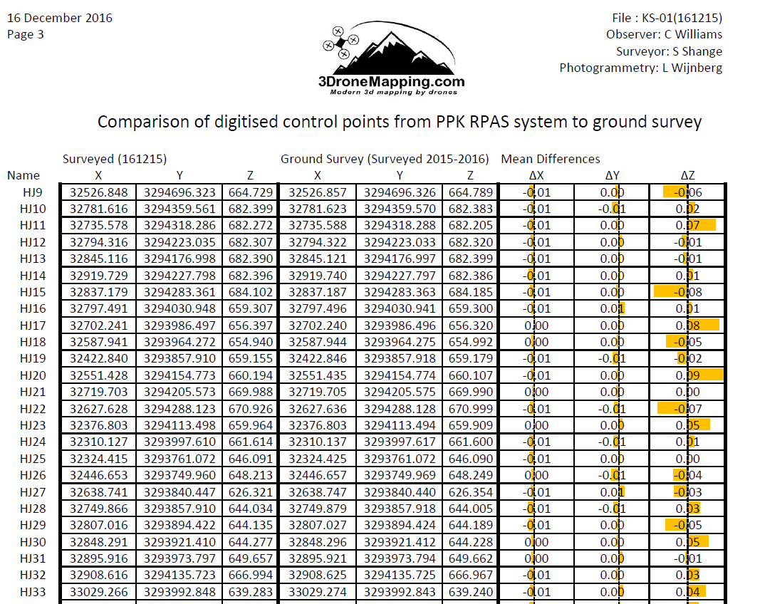
Control points were digitised from resulting point clouds and orthophotos and compared to the previously surveyed. These positions showed almost no difference to the control as published. Areas that have previously been a problem for photogrammetry showed up even and consistent between surveys when drawing profiles or cross sections. The 200 control points varied only a few centimeters over the entire site giving a very accurate and tight model.

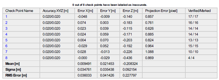
The final fieldbook and comparison for the survey can be found here:
As a brief synopsis of the results, the maximum deviation of points was no more than 0.09m in all axis. This is an incredible result given the fact that the average pixel size of the resulting imagery was 0.045m. It is interesting to note that the average mean error in all axes is 0.00m! But this is meaningless as it is an average across the field. The maximum deviation measured between session as a profile or cross section indicated almost no shift at all, meaning that the data is consistent between sessions. This is close to impossible under normal operations with ground control points.

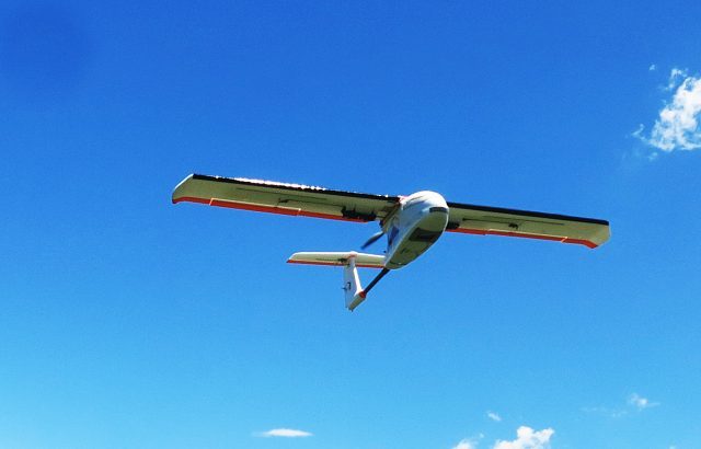
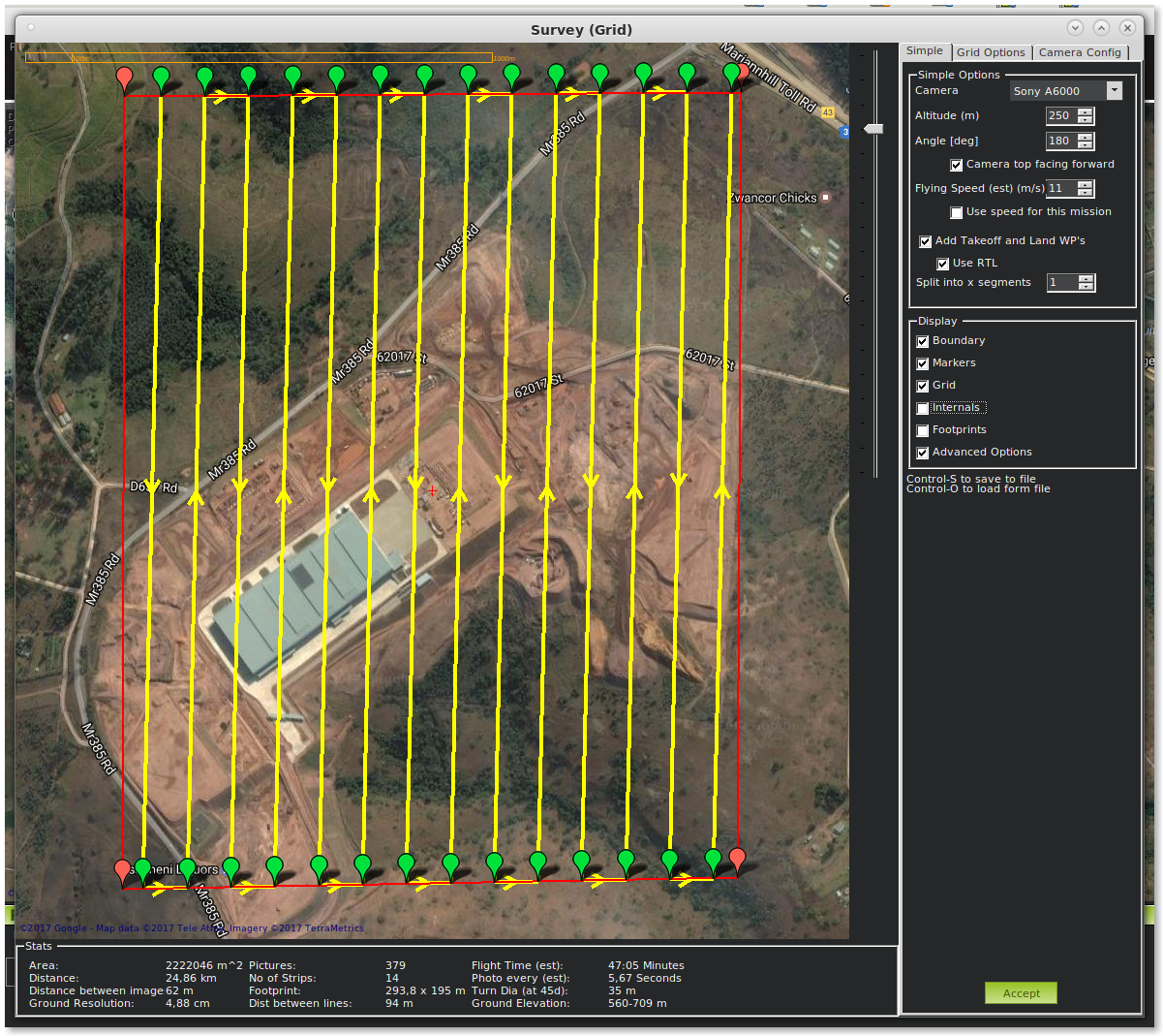
The aircraft used was a fixed wing RPAS carrying a Sony camera with fixed focal lense A total of 836 images were collected at 800ft AGL, with a 68% side and overlap. The test area is 780ha big and takes 45-55 min to fly at an average speed of 19m/s. The Reach was recording data at 14hz, GPS only. The ground survey completed with Leica GPS1200 checked measurements to 0.02m horizontal and 0.03m vertical accuracy with all points checked and meaned

  • PPK setup using Sony A6000 camera, 20mm lense, EMLID Reach with flash sync, Tallysman TW4721, ReachView beta v2.1.5
  • PPK base running EMLID Reach, TW2410, ReachView beta v2.1.5
  • PPK post processed in RTKPOST ver2.4.3_Emlid_b26
  • Photogrammetry done in Pix4Dmapper Pro Ver 3.0.17
  • Orthophoto resolution 0.043m, point cloud resolution 47.1 points per mÂł
  • Comparison digitised in ArcGIS V10.0
  • EPSG:2054. Hartebeesthoek94 / Lo31

What this all translates to is that surveys can now be undertaken with even less time spent in the field and can result in even more accurate and consistent data. But should you not place control at all? This is a bad survey practice as you are depending on only 1 set of data measurements. As a caution, we would still place only a few control points as a quality assurance test to prove to yourself and others about the precision of the data generated.
But you do not need to buy or hire a GPS for this as the very same Emlid Reach in the aircraft can be used to survey those control points just as accurately!

11 Likes

Really impressive work. Extensive and thorough

1 Like

Well done this work will save the rest of us a lot of work.

Thank you
Jim McArthur

Congratulatios Luke! Nice work there!

Some questions:

  1. Whats was the size of the ground plane you used on the plane?
  2. Did you try to do RTK or just PPK?
  3. Have you found out how much is the delay between the actual camera shot and the flash signal or it is negligible in front of the other errors?

Thank you in advance and congratulations again for the nice work!

It is 65x65 aluminium foil. Not the best but it works fine.

We try and keep the workflow as simple as possible in the field. RTK is too complicated and unnecessary for our needs. For such a BVLOS flight, you need to be on your toes and actually do some work like radio calls for other aircraft, failsafes, etc.[quote=“rafael.lehmkuhl, post:6, topic:4613”]
Have you found out how much is the delay between the actual camera shot and the flash signal or it is negligible in front of the other errors?
[/quote]

There will be a delay, but we don’t think that it is very much. It would be visible in the camera position estimation. We do fly fairly fast so in theory this delay would be exaggerated.

I think there is a problem here : 780ha with 68% side/overlap at does not take 45-55min at 800ft AGL. One hour more is missing ! Some pictures are missing to achieve 780ha.
45-55min is for 450ha @19m/s with 68% over/sidelap and 250m AGL. 836 pictures give also around 450ha.
You have the magic skywalker 1800 flying at 19m/s. A more reasonable speed is 12m/s for this plane or you have a good receipt !

Minimum coordinates are
x,y
32212.761,3293436.163
33542.030,3295123.150

It represents a bounding box of 225 hectares. So control points are not over 780ha but only in this area. You flight log look like 250ha but not 780ha

2 Likes

@Sylvain_POULAIN, The area pictured is not the complete calibration site. It extends much further but we do not show our flight paths due to privacy concerns. We also fly cross strips too at lower altitudes for the same area as we have more detailed control on the same test area that requires better pixel sizes.

The total test area is indeed 780ha but we may be wrong with the timing thereof as it depends on other air traffic taking preference. For that, I apologize for misleading you and making you break out the calculator! The point is to indicate how accurate PPK and photogrammetry using Reach can be, not to advertise our endurance, aircraft design or calibration site.

We are not using a Skywalker as pictured for this work but an IC plane of our own design. We do not publicise it for obvious reasons. The Skywalker pictured is also used for this test site but has a different power/motor setup that gives it a very economical cruise of 17m/s. We get a decent 50min with it at that speed carrying an A6000 landscape…

1 Like

Ok I understand, but IMO, these incohenrent values discredit the ppk test. It’s confusing a lot ! And I’m sure I’m not the only one to compare what is written to real datas.

Nice test indeed and thank you for sharing

2 Likes

What lens you were using?

EL

1 Like

It’s written in the document : 20mm lens. So I think, it’s the common Sony 20mm pancake lens

1 Like

Hi Luke!

Great work! You have collected quite a lot of checkpoints!
We have an almost similar setup with a6000, 20mm lens and reach with tw2407 antenna and Leica icon60 GPS for surveying, collecting raw base data for post processing. We are doing lever arm compensation (I assume you are doing as well) to account for the antenna - camera offset and flying a skywalker with 15m/s at 250 m height. Unfortunatelly we are not able to get the accuracy you achieved, especially in the height, which has an approx. 20cm offset, almost always (like the one I shared below). What do you think, can it be caused by collecting the control points a week in advance w.r.t. performing the flight? On average how much time has passed for you between surveying ground points and doing the flights, and have you seen any correlation with respect to this? Thanks for your response in advance!

Project processed with checkpoints:


Points enabled as GCPs:

@vbnhu, there should be no difference between collecting points over a time period. As long as the ground has not moved or that they can be positively identified. Some of our point used in the test are over 3.5 years old.

Our antenna is directly over the camera. We add an offset manually to compensate for the height difference. Images are not included on banking the aircraft which would change the offset a bit.

Given that your X and Y coordinates seem ok, it leaves me to believe that there is something wrong with the Z. The Z differences all seem to be in a similar order (-0.17 or so). I would guess that perhaps you have calculated the offset incorrectly or that the devices that you used in the field to observe the checks have not been offset correctly on the pole or tripod.

Point 8 seems like an outlier and I would discard it. It also appears in only 4 images.

I was just curious if you collected the GCPs with reach also - with the same base station - so systematic errors related to NTRIP mountpoints could be elliminated or not.

We also use only the images from the straight segments, but we have 9.2 cm vertical and 3 cm horizontal offset of the antenna, so we need the lever arm compensation.

Yes, point 8 is out of the area, but still interesting to see the statistics related to it, even though it is visible from 4 pictures only.

Unfortunatelly the compensation is correct, if I change the sign the error becomes 40 cm rather than 0 cm. We did 10 projects, each of them 1.5 km2, and in some of them the height was correct, also x and y. So I have the suspicion that the error comes either from GNSS post processing - different days, different ionosphere and trophosphere conditions - or from pix4d not finding the global optimum during the camera parameter optimization. It seems like you have not encountered anything like this?!

We have collected various QA points over the site with a variety of instrument including theodolite. The Reach and subsequently the ReachRS were also used for asses the quality of the measurements.

We do not have the luxury of NTRIP servers or VRS at our site, so I cannot comment on that.

We have used NTRIP station data at other sites with no problems at all. The only time we have seen shifts like yours is when we have made an error in determining the antenna height at either the base or rover, or if we have used an incorrect or global geoid model.

Sorry I cannot assist further.

Dear Luke!
Thanks for your response! Looking even deeper I have the suspicion that the error is caused by Pix4d not by GNSS hardware or software, since with “standard” processing options I got an average Z error of 11 cm, while with alternative processing option it becomes 20 cm. I will contact them to clarify what might be the reason (and also try other photogrammetry software). Best Regards,
Balint

Hi!

I wound up here after looking for more info on the Emlid receivers and im sure glad i did! My question is more of a practical one with the receivers. How does the GUI work? Is it easy to switch between PPK and RTK modes? How do you tell the system what height the bipod is when you’re collecting GCP data etc?

Cheers

1 Like

Hi guys… I have a doubt about this precision… The GPS unit in the aircraft have a Reliable inertial??? Because i saw a good and reliable inertial a few years ago costing about US$200,000… I just want to know how reliable is the inertial…

Inertial central unit is usefull for lidar. Photogrammetry and SFM compute orientation better than an intertial central unit.
You just need coordinates of center of picture.

4 Likes

Hi Sylvian… Thanks for your fast reply… I understand that i only need the center of the picture. But do you agree with me if i have some wind and get 1 degree of pitch at 200m high. How fast can it be processed by Reach to get a reliable geotag of this photo?

1 Like

It’s not an issue, photogrammetry will calculate it and apply this pitch.
For general purpose, it’s better to have pitch than 0° pitch

2 Likes