


Can I attach my battery to any of the two ends of the power module, and then extract power from the other one? Or is there only one allowable configuration?
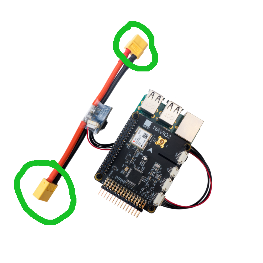
The battery goes on the connector on the bottom of your picture. If your lipo already has a XT60 connector, it should not fit the other way around. If you need to solder other connectors to your lipo or your power module, please be careful while soldering connectors to lipos. Any short between the poles may cause a fire! Always prepare and solder only one pole at a time. The power module is the safer option to change the connectors. The general rule for power connectors is, never solder male connectors (the ones with pins) to the power source. The power source ( lipos, the wall sockets in your house etc.) should always have female connectors. This way the chance of shorts is much lower.
1 Like
Thanks a lot for your advice! However, after posting here, I kept on reading the docs. In every scheme presented here , the battery goes into the other connector. This also seems weird to me, since that means that my battery needs to have a male XT60, which, as you said, is not conventional.
Could it be that all those “official” schemes are wrong?
Yes, it seems they are wrong.
Sad to hear that. I actually tried that (wrong) configuration after seeing those schemes, and things didn’t work. Then I connected it the right way, but the raspberry just reboots every 3 or 5 seconds, showing the lighting bolt icon (which indicates that it is not getting enough power). After that I tried another power module, connecting it the right way, and it worked perfectly. So I guess I damaged the first module 
I hope people at emlid can correct those schemes before someone else runs into this.
Hi Lucas,
Thanks for the report! The connection schemes in the docs will be fixed in the nearest time.
However, I wanted to ask if you re-soldered the connectors. It’s rather difficult to connect the power module in a wrong way without re-soldering, because, apparently, you can’t connect two male plugs with each other.
The LiPo battery I bought had a different kind of connector, so I bought some XT60 connectors and soldered a male plug to the battery, so that I could attach it to the female plug of the power module (as in those schemes). After @schuermannsebastian’s answer, I desoldered that plug from the battery and soldered a female plug. Now things work just fine, but I had to use a new power module (sadly).
Lucas,
Sorry for this inconvenience, however, in case your power module was connected to a male plug and the polarity was correct, the module shouldn’t have been damaged. Could you please double check it is soldered in a right way now?
I’ve just checked it again, just in case. But there is no room for mistakes. I keep all my setup unchanged, replacing one power module for the other, and vice versa. With one power module (the new one), things work ok. With the other one, the Pi just reboots on and on, and if I plug it to a monitor it shows the lighting bolt indicating not enough power. If plugging it the other way around shouldn’t have damaged the module, maybe it was just defective to start with (but it seems too much of a coincidence to me).
Just to clarify: I didn’t tamper with the power module. The thing I soldered and then re-soldered was the connector of my battery.
Hi Lucas,
Let’s investigate on why the first module is not working.
I’ve just emailed your colleague.
This topic was automatically closed 100 days after the last reply. New replies are no longer allowed.