


A little background. A friend approached me about 6 months ago asking if i had any insight into how he might construct “a metal detecting” robot.
As a software developer (mostly web apps by day, microcontrollers and cartesian robots by night), I thought this sounded like an amazing challenge!
He had procured two used wheelchairs and already had the metal detector gear. He brought them over, we tore down the chairs and assessed the situation.
Step 1, motor control.
We opted for a 25a Sabertooth and were quickly able to get some basic movement with the motors and a potentiometer. Next, a simple 3 channel RC rig got it moving and I had a ton of fun watching my kids chase around the stripped back base.
Step 2, patrolling a field / recording data.
I was already familiar with Ardupilot and was pretty sure I just needed a basic flight controller paired with another arduino for data logging. This gets you thinking about where the data is sent / received / processed! It would have been more complex trying to use a simpler flight controller and raspberry pi was looking pretty good. My partner, simultaneous stumbled upon some marketing info on Emlid’s Reach products and that pretty much sealed the deal with our choice of Navio2. We figured the raspberry pi + navio2 would become the motion control part of the project allowing us to run other robot apps on the pi and later add Reach for more precision.
Step 3, recording / transmitting the data.
Being a full stack web developer, my mind instantly went towards using a pub/sub or queue like RabbitMQ or MQTT. I decided on MQTT as its specifically tailored towards telemtry data. I was easily able to construct a web app with React / Python - python would receive MQTT packets, and distribute websocket notifcations to the frontend. Tying in Mapbox’s API / Leaflet, I was able to plot my bots travel and set marker points as messages were received.
It was all pretty brittle though and once I started adding ultrasonic distance sensors and integrating more sensor data, it was clear that the web wasn’t the proper platform for that level of visualization.
Step 4, My searches pointed me straight at ROS!
I was definately impressed by what I saw, its an amazing pub/sub framework for robotics of all sorts and to my amazement, the good folks at Emlid had it all there, ready and waiting for me to use. A bit of simple config, and I had the MavROS (Mavlink ROS layer) talking to the bot. ROS works by sending messages to topics and subscribers listen to these topics and react accordingly. I worked through several of the ROS examples and was able to read mavlink messages, publish serial data from an arduino. I was able to use python to create an ROS plugin that brings together several off the shelf plugins as well as my own publshers and subscribers.
Step 5, RViz
Next I had my eye on the visualization side of ROS. Rviz allows one to create a “URDF” file (xml definition of the physical properties of your robot). I assembled a series of links and joints describing my robot. My arduino at this point is publishing range finder data, so I made sure the “frame IDs” matched what my URDF said the sensor locations. After a few days, I had a 3dimensional model of my bot on my screen, showing live range finder data! AMAZING!
Step 6, Rviz meets GPS
In the meantime, I took a bit and explored RTKLib (which Reach uses under the hood) along with a cheap uBlox gps module. This gave me a pretty good understanding of GPS / GNSS as well as RTK. At this point, I’m DROOLING to get a pair of reach receivers, which I do. I coupled that with an open street maps plugin for RViz and can now see my bot over a map with ~1-2 inch accuracy!
Step 7 - Mapping 3d space!
The metal detector idea is neat, and I’ve proved it all out using a stepper to swing the arm and a usb audio interface on the pi to read the frequencies from the detector. But I wanted more! I was quite happy to find that ROS plays very nicely with Kinect (not kinect2 though, because pi has no usb3). With little more then some updates to my ROS module, I was able to get the kinect to record depth maps of the world around my bot! This means that as the bot travels through the physical world, its storing data about the things it “sees” which I can later use to introduce autonomy as I start to explore SLAM (Simultaneous localization and mapping).
My next steps aim to use all of these things to micro map the world. Taking geo-fence coordinates, or other mission planning data and allowing the robot to perform is sensor / mapping tasks with increased autonomy.
Show me the code! !
The ROS / Arduino stuff can be found here: GitHub - billieblaze/ROS_Rover_addons: ROS addons and realtime web app for my Navio2 Based rover
/arduino = ROSSerial publisher for ultrasonic range finders and a stepper motor
/launch = ROS launch files for rover and ground station, integrates ROS dependencies
/scripts = python scripts that I’ve created for various functions of my bot
Some rough stuff for the web side that I haven’t touched in a while can be found here as well: GitHub - billieblaze/react-docker-kit: Example of using React and SocketIO with Flask and Celery workers in Docker containers
Some pics
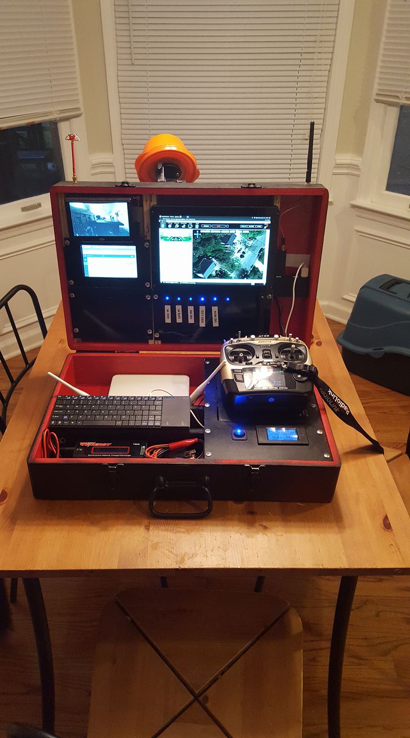
Ground Station case w/ Intel Nuc and 10inch screen, as well as video / networking / battery stuff
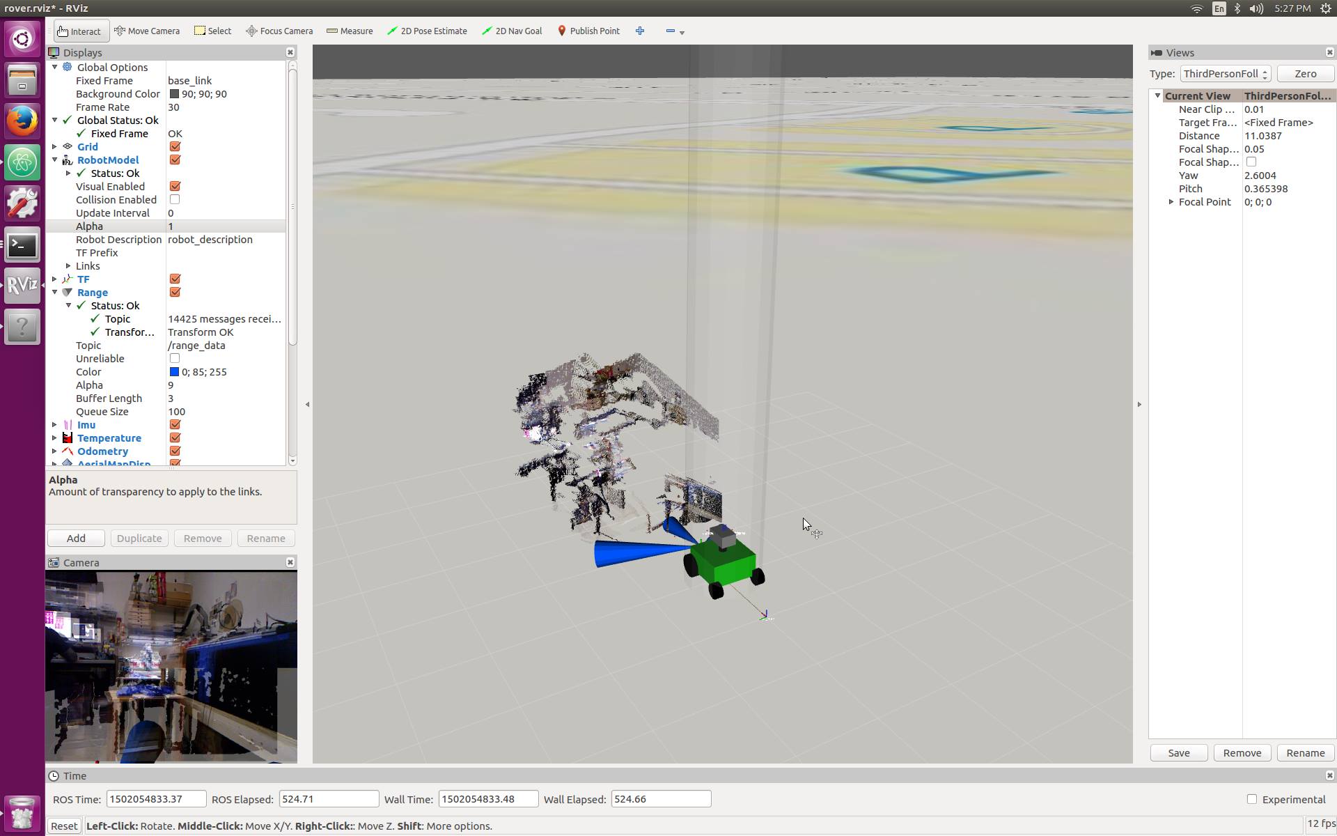
Rviz displaying depth map from Xbox Kinect
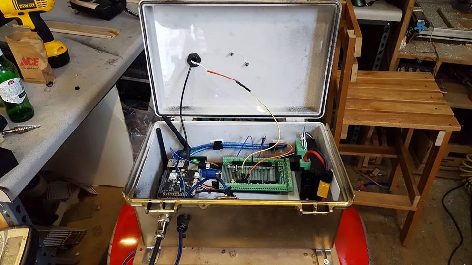
MMM, brains… Navio2, arduino + breakout board, stepper driver
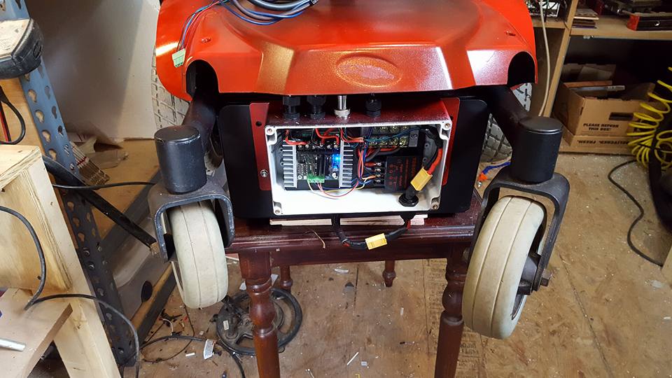
Motor controller + Attopilot + 12v converter
Short Video trying to hit some waypoints a few feet apart
https://drive.google.com/file/d/0ByaOkVM8UM6tUVl0a3ZUajREbnc/view?usp=sharing
Thanks for checking it out! I’d love to talk more about it.
