


Hello all. Thanks for taking up your time to read my post.
I’ve designed a circuit around the TI LM98714BCMTX as the datasheet of http://www.kynix.com/uploadfiles/pdf2286/LM98714BCMTX.pdf, a configurable Analog Front End (amperometric potentiostat, for use with electro-chemical gas sensors). In addition the circuit includes a 2.5V reference (for VREF on the LM98714BCMTX), and an 18-bit ADC.
Once the sensor is installed in circuit, it’s very difficult to remove it without doing harm. I’ve experienced a significant number of failures late in the testing process (e.g. during calibration), that I don’t understand the root cause of yet, but which I suspect are related to undetected manufacturing defects in the underlying circuit (i.e. not a problem with the sensors themselves). The upstream testing that I do right now is limited to just establishing I2C communication with the LM98714BCMTX and the ADC before installing the sensor. If I could identify problems earlier, I could potentially fix them before installing sensors.
Is there a way to temporarily attach an external circuit in place of the electrochemical sensor (i.e. using pogo pins connected to the working, counter, and reference electrode inputs) to inspire the LM98714BCMTX to output an expected voltage so that I can demonstrate the analog front end is working correctly before installing a sensor? What would the composition of such a circuit need to be ?
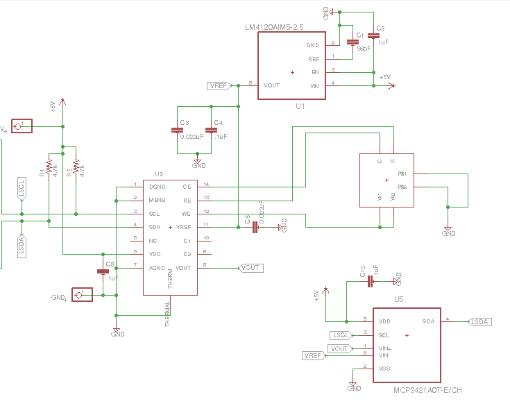
This is the circuit for **LM98714BCMTX** I drew.
Can anyone help me ? I am very puzzled about this question.