Testing accuracy of M+ PPK on Phantom 4 Pro

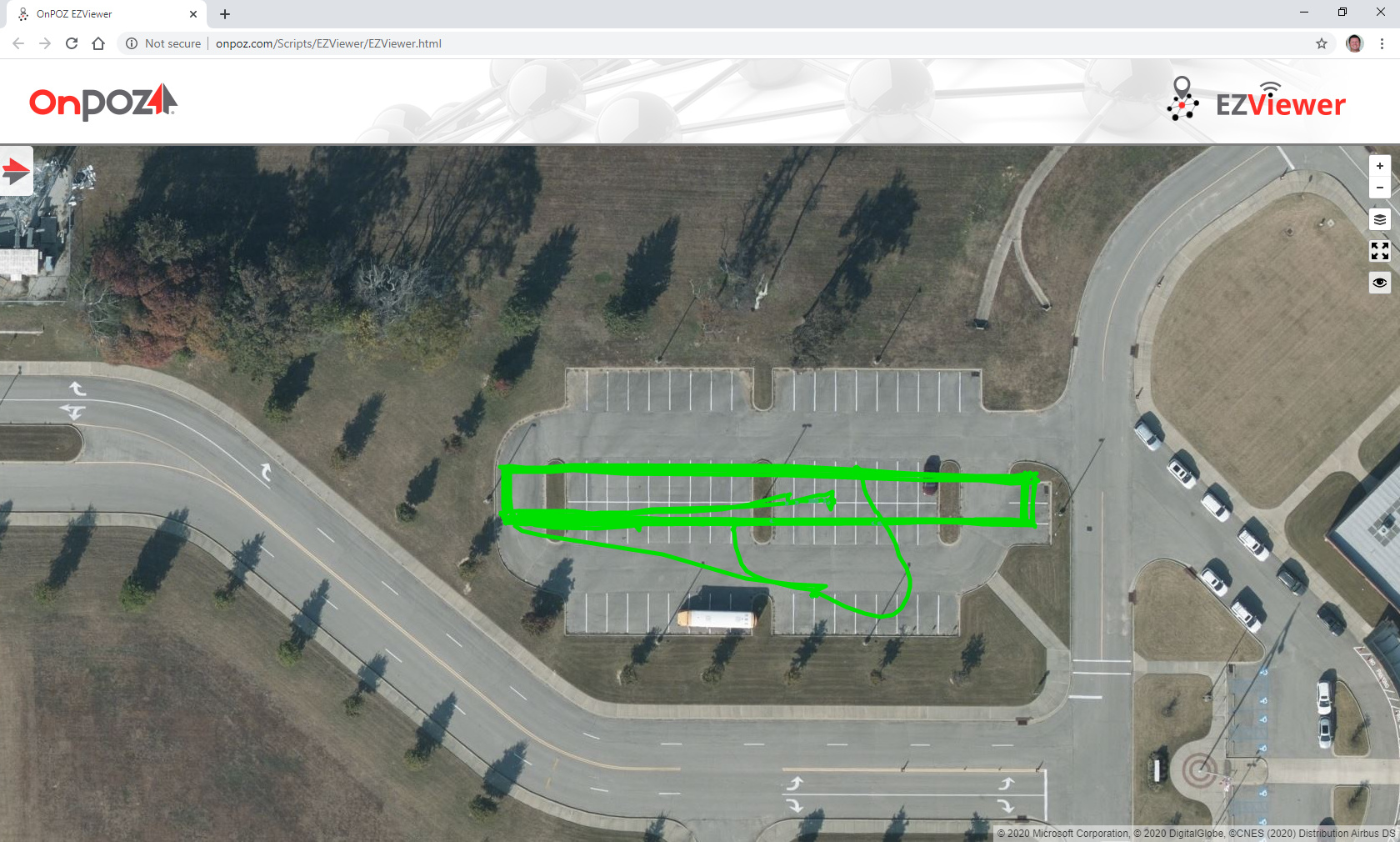
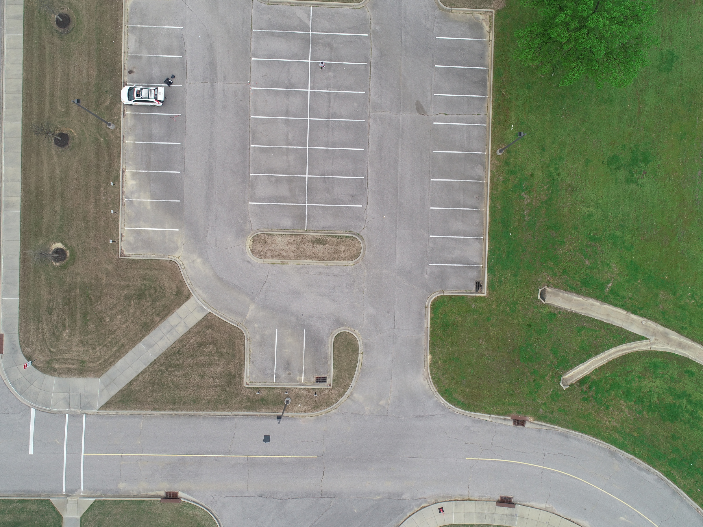
I have been wanting to test the M+ accuracy for the PPK setup so I gave it a go. I setup Litchi to fly back and forth over a parking lot. I surveyed the stripes on the parking lot (center line and every other stripe). With the M+ mounted I just manually took photos as the P4P flew over the stripes.
The purpose was to take the center pixel of the image and compare that to the PPK value.

I also wanted to test various timing offsets and try to find the absolute most accurate over a whole set of photos. All photogrametry software takes the yaw, pitch, and roll of gimbal into the calculations when stitching. But for the purpose to “testing the accuracy”, I need to have a formula that will show me where the PPK value “should be” and then I can compare that to where it is.

Steps So Far:

  1. Flew mission in Litchi with Camera set to 90°
  2. After surveying the parking lot stripes, I entered that into software in UTM 16N.
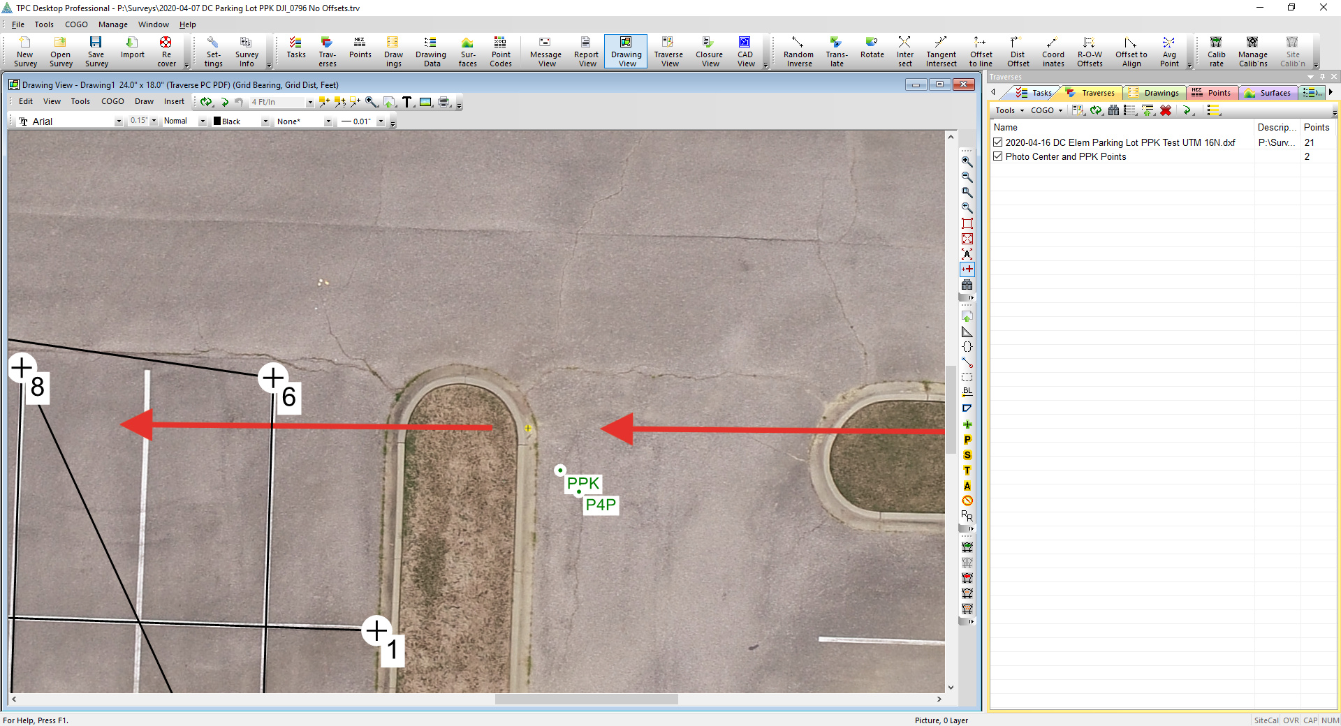
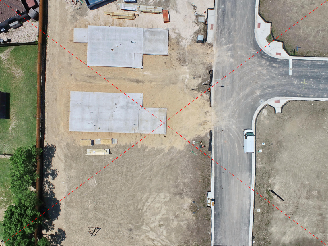
  3. I took the P4P photos and marked the very center pixel for a reference
  4. I brought the photo into TPC and calibrated the image to the drawing so that it was geographically placed correct.
  5. I then processed the M+ flight and entered the location on the image.

What I need help with is having the correct math formula to account for the yaw, pitch, and roll of the camera/gimbal when the photo was taken. It will slightly different for each photo.

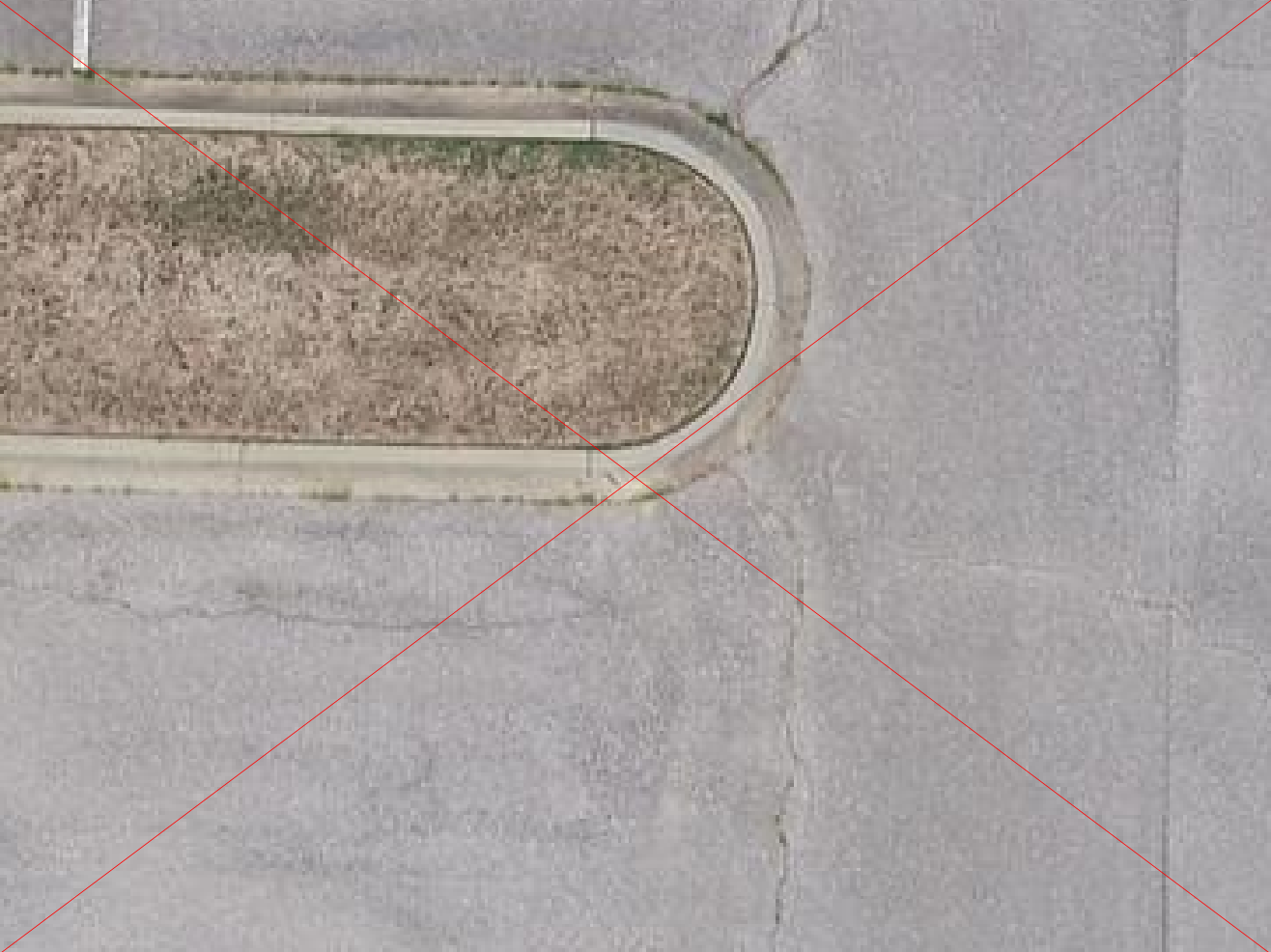
If I have the center point of the photo, and the PPK location of the M+, then we should be able to mathmatically take the yaw, pitch, and roll values along with the altitude to triangulate back to the center point of the photo. The difference in the calculated point and the actual point should show the accuracy. In the attached image, you see the image center point, and the locations for the P4P onboard gps (original photo gps) and the PPK location of the M+.

But I don’t know how to come up with the formula. Can anyone help with that? Or if my thought process is wrong, let me know that too.

1 Like

That is going to be a fun test. Can you explain a little more about the setups?

What gear and settings did you use to collect data originally? RTK/PPK?

Are you using the same base station and coordinate to correct both the rover and the drone?

Is the antenna directly over the center of the sensor and do you have the vertical offset value? That may make a difference as well when having to account for pitch and roll.

1 Like

Hey Michael, So I made some errors on the first go around… I did not log precise wind conditions and I did not use a good method for logging the flight parameters. So when I go do this again, I will go on a day when there is zero to little wind and I will lay down a chalk board and write the flight paremeters on it so it will be in the photos.

I had my RS2 setup as a base station and mounted the M+ on the P4P. Used 5hz and did PPK processing in EZsurv. (btw, thank you for doing the video on PPK in RTKlib. long time needed so folks will appreciate that!!).

I only flew in east west direction. At first I thought I could just compare the Center pixel location to the PPK location to check the accuracy. However, it dawned on me that I have to account for the pitch, roll, and yaw of the camera. If I was taking photos at 45° camera angle, then that does not change the GPS location. But we should be able to use a specific (and constant) formula that will take the Center pixel actual location, and then apply the formula using (PPK location, altitude, pitch, roll, and yaw) to work from the PPK location back to the photo center pixel location. This triangulation will then provide the absolute accuracy of the PPK.

This is only necessary for checking accuracy. Pix and DD are taking the pitch, roll, and yaw data into consideration when stitching, but in order for us to check accuracy, we have to it for a single photo.

The pitch, roll, and yaw, data is in the EXIF data. But the method of calculating is beyond my abilities. So I was hoping someone could work up the formula.

The parking lot stripes (down the center of parking lot ) has already been surveyed, so flying over it again for full and complete test will be much easier. If there are some guidelines you think I should use then I will fly it again on a hopefully near no-wind day.

If I fly it again with good records and on a near windfree day, then I think some very accurate details can come from this. Thanks for the reply.

1 Like

remember that the encoders for angle measurement in the gimbal also have some degrees of error. Usually around 3-6 degrees, especially on the yaw. On the ground, depending on the altitude that can give several centimetres of error.

On top of that, you will need to take into account the distortion of the lens. In photogrammetry, that is usallu done by either having a calibration of the camera, or by simply having enough images and then estimating from that.

1 Like

Good point. I guess I just want to take all that we know and come up with what seems to be the best available calculated accuracy. It could be 3 inches to 3’ or more. Then we will at least have a range and then on top of that, you would know that there can be other errors unaccounted for.

I think the most realistic thing you apply is measure out 10-20 Ground Check Points (no control, just to be mean) with your Rover and then fly with your P4P. Correct both the Rover and the P4P flight with the same Base.

Tag your Ground Check points in the photogrammetry-software, and now you have your precision.

3 Likes

Michael, I failed to answer a few questions. I am using the same base station to correct both. However, the survey for the lines was done on a different day. I put a benchmark in the asphalt when I surveyed the stripes and set a backsight point in case I needed to do it with a TS. Stripes surveyed with RS2 Base/Rover.

M+ flight done with RS2 base (but it was not set over the benchmark used when doing stripes. I just stuck the base out there and used it for PPK.

On the next flight, I will set my BASE over the benchmark just so it is done from the same location.

I have the kit from Tuffwings so it is very close to being over camera center.

2 Likes

This is essential !
Would also be interesting to see the GNSS results compared to the TS result!

1 Like

I think you are going about it a great way. You definitely need to use the same base on the same point. You could always bring the pictures into a photo/graphics program and draw crossing lines from corner to corner to get the exact middle. Also make sure you have your rule of thirds lines on your display. This will help you center a mark on the ground much better.

You may not be able to tell but on the screen shot of the drawing, I have a yellow circle which is the photo center point but the red cross makes it much more evident. I know that Christian mentioned about doing this DD or Pix4D and while that will give an average of the accuracy, I wanted to see the raw accuracy before it goes into DD or Pix (mainly to see the consistency between multiple photos). But someone will still have to help with the trig equation that is needed to calculate the location based on pitch, yaw, and roll.

It may take a little bit but I think this will get done and have some good info. Thanks again for the feedback!

Christian,
After this is done, I will go to a much larger parking lot at the high school and that will be good to do a comparison between GNSS and TS. I too want to see how it compares. At that school there are some decent elevation changes that can be compared for vertical accuracy in all of this.

I think I see it and it looks like you got pretty close! Don’t forget about QGIS… It would be a good test to enter the coordinates of your rover shots and create a KML to import into Litchi… Wait until we can do stakeout with a drone! :astonished:

On this I found out that the camera pitch was at 89.9 degrees. This would amount to a 4" difference at 200’ AGL. After talking to a surveyor buddy who does mapping, it would be much better to spend time comparing the different methods on the same mission (ie 1. Drone GPS only, 2. M+ PPK on the Drone, 3. M+ PPK and using GCP’s. So I will do that. Given the fact that there are multiple factors on this, much of which is above my knowledge level, I will spend any free time doing the comparisions of solutions on the same exact flight. Thanks to Michael and Christian for the input!

1 Like

On that note I would have to disagree with your friend. At this point we all know what the accuracy expectations of running missions each way are. There are countless studies on this and the DroneDeploy forums alone. I think it is a very important thing you were coming across which is to know the true characteristics of your aircraft. This is one of the major selling points of the Phantom 4 RTK that is actually valid. Camera calibration. For instance - If you have two Phantom 4 Pro’s is one better than the other? What’s the best way to find out. That’s the question.

Hopefully the stored calibration data on P4 RTK takes into account the focusing?
At least on the P4Pro, focusing hugely affects precision, when using a calibration-file. My calibration-file is made by flying over a 500x400 meter site with 50 GCP’s shooting 700 images, with focus set to infinity (for having an easy hard-stop).
If the focus is set in the middle instead (that still gives sharp image at 27 meter and at 70 meters altitude), my check-point values are suddenly 2-3x times worse.

This topic was automatically closed 100 days after the last reply. New replies are no longer allowed.