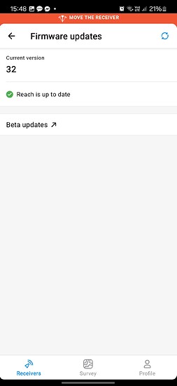
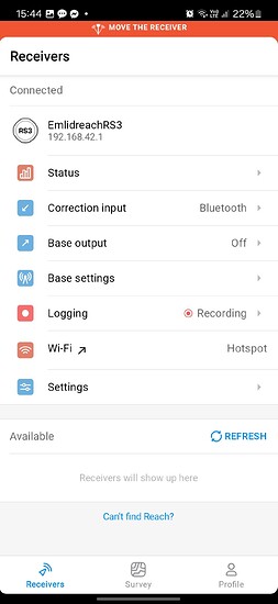
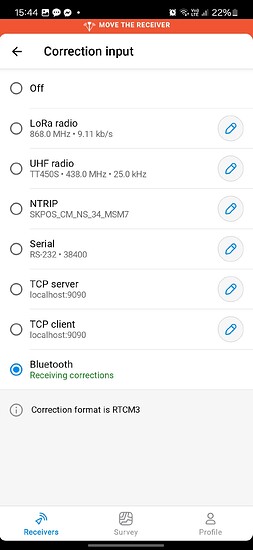
HI ofuentes.sigman tried the app. I really like it. It even supports IMUI TILT in software.
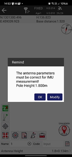
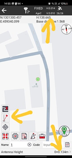
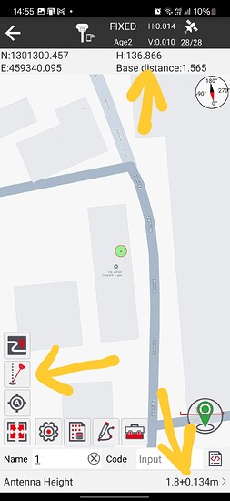
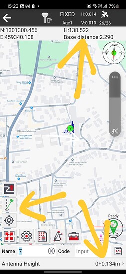
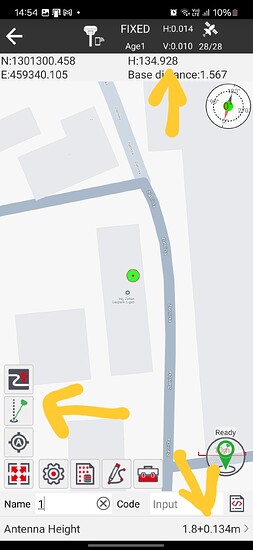
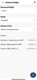
But I have a big problem. I can’t set the height correctly on it. If the TILT compensation is switched on, the pole set height is subtracted twice from the height of the antenna.
e.g. the correct height of the point: 136.87m. The height of the antenna is 1.8m. The measured data when TILT is on is 134.93m. Math (136.87 + 1.8) = 138.67 is the height of the antenna. difference is 138.67 - 134.93 = 3.74m divided by 2 = 1.87m
Do you have any ideas or should I write directly to the developer for help?
I would in the meantime.
Hi. Timd1971
It doesn’t solve the problem. Field Genius support is also aware of the problem. They wrote the following: The Tilt is configured through the Emlid Flow app, so we are not able to control it in FieldGenius.
RS3 and Field Genius work beautifully on this link. But since the updates it is not working properly. Since the Emlid antenna does not emit a sound signal if it loses Tilt compensation, it is not known in the third-party application whether the transmitted data is compensated or not. And according to your video, to create 2 profiles. One is Tilt ON and the other is Tilt off? I was bought this GNSS to perform tilt compensated measurements.
Broadcasting already compensated measurements from the Emlid Flow application is, in my opinion, not a good solution from any point of view. You have to change the height of the stick many times during the measurement. And that should be in the Emlid Flow app. Because he calculates the compensated measurements and transmits them based on the height. To be honest, jumping between the two apps (Emlid Flow - Field Genius or other) is very unprofessional.
Hi @zoltan.gasparik,
Thanks for your email and detailed explanations! Let’s continue our discussion here, as it might benefit other users too. I’ve split your points into two comments to address each one:
You can specify it manually in Emlid Studio. Just hit the Edit button in the rover or base section. It will open the following menu with all the required settings:
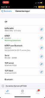
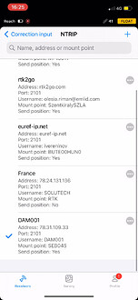
You can manage your NTRIP services in the Correction Input tab.
I completely understand how a sound alert would be helpful when working with a tilt. I’ve added your suggestion as a +1 to our feature request list.
That’s a really interesting idea! I’ve noted your request.
You can add an extra point at either end of the line in Emlid Flow. To insert between the points, you need to add first to the end and change the point order to place it between the points.
We don’t have arc support for now. I’ve noted it as a separate feature request.
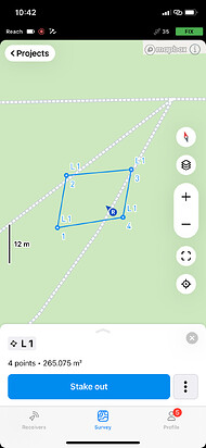
We don’t support closed polygons for now, but this feature is on our roadmap. I’ve added your request as +1.
I got it! I’ve added these customization features to the list. Just so you know, Emlid Flow already supports importing and exporting DXF files.
I understand it’d be easier to differentiate by layers and color, so there’s a +1 feature request.
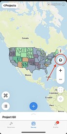
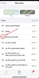
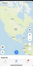
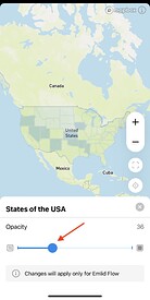
Emlid Flow allows the toggling of WMS layers on and off. Here is how it should work. Does it work the same for you? If not, please share a screen recording.
Usually, Emlid Flow automatically increments point names (e.g., 1, 2, 3). If this isn’t working for your workflow, could you please provide more details? I’d like to ensure I’m addressing your specific needs.
Thank you for your suggestions! I’ve passed them on to our developers. For now, you can navigate by following the blue icon. We also support staking out by distance and direction.
Thank you for passing along the Field Genius reply. Let me double-check everything and get back to you later.
Hi Zoltan,
I’ve been testing Field Genius version 2.6, and it looks like the tilt compensation is working as expected with the custom ETC messages we’ve added from Reach. Since Field Genius supports these messages, it can calculate the tilt-compensated position on its end.
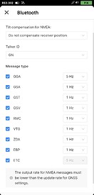
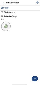
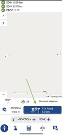
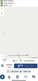
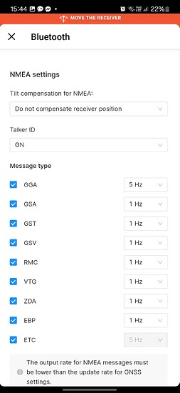
In the NMEA settings, it’s important to disable the “already compensated” option and enable the ETC option. In Field Genius, make sure the Tilt correction is activated, and you can check the tilt status in the bottom-right corner tab.
.
Also, just a quick note: the antenna height should only be adjusted in Field Genius—there is no need to change it in Emlid Flow.
Does it seem to be working the same way for you? What are you seeing on your end?
Hello
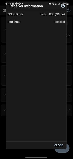
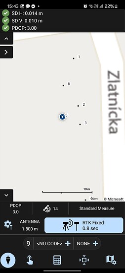
Unfortunately it doesn’t work. I don’t know what could be the problem. I will send you some photos of the software settings. Field Genius does not want to recognize the Tilt function and show the bubble. What am I doing wrong? I do not have a tilt correction tab in my GNSS rover profile. How can I eneble TILT?
Did you install the LATEST version of FGA? Version 2.6.2.9460
ok it work. THX
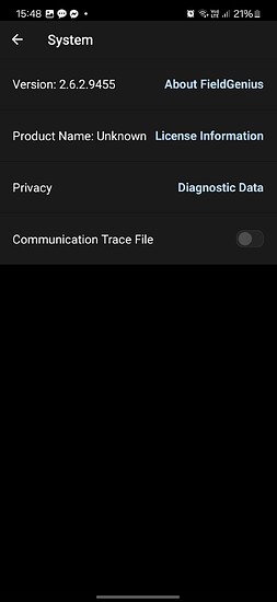
I had a 2.6.2.9455 Version .
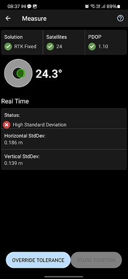
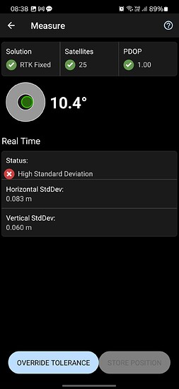
I had some time and tried the application. It was a big disappointment. The tilt function does read and show the tilt angle, but the results are disappointing. The attached pictures show that the FG cannot handle or calculate the exact coordinate with an inclined pole.
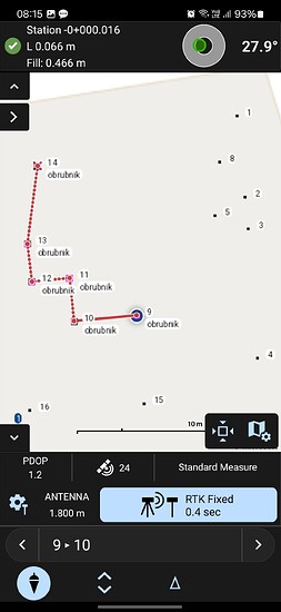
And finally, when I stand exactly above the previously messured point. When I tried to stake out with tilted pole.
I’ve also seen a couple of strange things that can happen when measuring.
If you don’t get the “High Standard Deviation” message (and I’m not sure what circumstances are triggering that in this case) it can measure accurately…even though the bubble incorrectly & confusingly shows a lean rather than staying centered like in stake out or in Flow.
The best way to confirm what’s happening in your case is test it over a known point.
I’m waiting for the next update and going by the historical schedule 2.7 shouldn’t be far away.
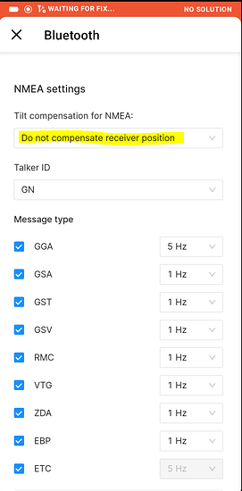
Just a check, in Flow do you have the Reach - Settings - Position streaming 1 or 2 - Bluetooth - NMEA/Settings - Tilt compensation for NMEA set to “Do not compensate for receiver position”?
In this case the geometry calculation occurs in FGA.
-
I thought that height correction could be done in the field. For example, if I am doing street mapping and for some reason I change the height of the pole, but I forget to do this in the software. After a couple of minutes, I notice that the heights do not match. I can do this in the field (and recalculate), because when I get to the office and the data is processed, sometimes a few days pass and we already forget which points and which data needs to be corrected. Or I need the correct height right away in the field, that I can tell the customer, or even transmit good data to the total station.
-
Yes I know it can import and export Emlid Flow .dxf file. Although, based on my experience, special settings are required and it is not universal. Also, the biggest problem is that it cannot handle text, symbols, layers, line thickness and other properties and colors. So I end up with a lot of black lines that I can’t recognize.
-
In the emlid Flow application, I can only turn WMS services on and off if I set this separately for each job on the Elid Flow 360 web interface beforehand.
Hi @zoltan.gasparik,
At the moment, the only way to adjust the antenna height in the field is to restart a new log. I understand that having the ability to change it on the go could be helpful for your workflow, and I’ve noted your suggestion for this feature.
I appreciate your insights on the DXF handling and have forwarded them as a feature request.
The reason we set it up this way is to have everything ready to go before the survey, so you don’t need to handle it in the field. Your suggestion for more flexibility in the field is valuable and has been added to our feature request list. Thanks again for your detailed feedback!
I tried to reproduce the issue on my end but wasn’t able to replicate the high standard deviation error. I’d like to investigate this further. Could you please share the data you collected from Field Genius?
Also, was the receiver set up with a clear view of the sky, or were there any nearby obstacles, such as buildings or trees?
Hi Zoltan,
I just wanted to keep you in the loop with some new features! Emlid Flow 11.3 now includes support for closed polygons in the Survey Plan. Here’s a link to the guide that explains how it works.
I’d love to hear what you think once you’ve had a chance to check it out!
-
I thought that height correction could be done in the field. For example, if I am doing street mapping and for some reason I change the height of the pole, but I forget to do this in the software. After a couple of minutes, I notice that the heights do not match. I can do this in the field (and recalculate), because when I get to the office and the data is processed, sometimes a few days pass and we already forget which points and which data needs to be corrected. Or I need the correct height right away in the field, that I can tell the customer, or even transmit good data to the total station.
-
Yes I know it can import and export Emlid Flow .dxf file. Although, based on my experience, special settings are required and it is not universal. Also, the biggest problem is that it cannot handle text, symbols, layers, line thickness and other properties and colors. So I end up with a lot of black lines that I can’t recognize.
-
In the emlid Flow application, I can only turn WMS services on and off if I set this separately for each job on the Elid Flow 360 web interface beforehand.
I have a lot in work…I will test some features
Hi Zoltan,
I’ve noted all your suggestions for future consideration and will keep you posted on any updates.
In the meantime, we’ve rolled out the polygon support feature that had been on our roadmap. When you have a chance to try it, it’d be great to hear how it works for you.
This topic was automatically closed 99 days after the last reply. New replies are no longer allowed.


