Hi all, I’m a rookie but have read all the docs and before I buy a couple of RS+ I’d love some feedback.
We build waterslides, we always have a surveyor come and set it out for us. Over the construction process a bunch of our setout points get obliterated and need re staking. I’d love to be able to do that ourselves rather than wait for the surveyor, $$ etc.
So my understanding is that I would use a base station over one of my known points that were already surveyed in 3d. Would that be accurate enough with the corrections from the base station (hoping 20mm or so accuracy)? Otherwise if I have a few marks that I have in my dxf file to check is it possible to check them and adjust the errors out of the system before I start setting out marks that are missing? Our footprint would be only a few hundred metres x and y, elevations only a few metres up and down.
Is there a simple way to locate my dxf file and import it into reachview or is there a better app?
If you get the surveyor’s WGS84 coordinates and depending upon how they setup the control you might have to do a site localization in order to get cm accuracy on the points. If they didn’t localize then you should be able to setup the base anywhere, collect their points and stake them out later. This may not be efficient if there are allot of points.
Another option is to bring the DXF into QGIS and extract points from the lines. Problem here is that you probably want offsets in order to protect your points against getting wiped out again. In this case you can offset the linework in CAD and then bring it into QGIS. Once you have those points you can import them into Reachview in the WGS84 format that is required. If you are importing the points you will need to be setup on a known point and manually enter the coordinates into Base Mode.
Another option is to use a third party survey program such as MicroSurvey FieldGenius or Carlson SurvCE / SurvPC. You can localize etc as ReachView Survey is limited at the moment for what you can do. There are Android apps such a Mobile Topographer, Tersus NUWA, MapIt GIS PRO, etc, but I do not really use those, but others here do.
ReachView Survey is for the most simplest of data collecting and Stakeout, but you can use @michaelL advice to get it done.
If your making good money in business doing this, it might be a good idea to get (2) RS2 multi-freq receivers rather than the single L1 frequency Reach/RS/RS+. If you are around a lot of buildings, powerlines or trees etc, the RS2 would be best. Or even better yet get a Robotic Total Station or a Leica 3D Disto for automated fast layout! You can actually get by with a Leica Disto S910 “PRO PACK” also if you only need to stake out 30 points or less at a time. Check out youtube on these devices.
Exactly. That’s where I would go if your work required localization for max accuracy. @murraystuartbooth, what is your tolerance? A tenth of a foot (3cm) is pretty standard where we work.
This is more about replacing string lines and long tapes for resetting marks which is slow and unreliable, I definitely don’t want to set our jobs out. I guess my question was more about being whether there was a mechanism for adjusting the accuracy of the base and recover by using a few existing marks that are known. Say if I set up base on existing known location, and then check a couple of other known marks and they are off by some amount is there a way to use these points to correct from or is that not really a thing?
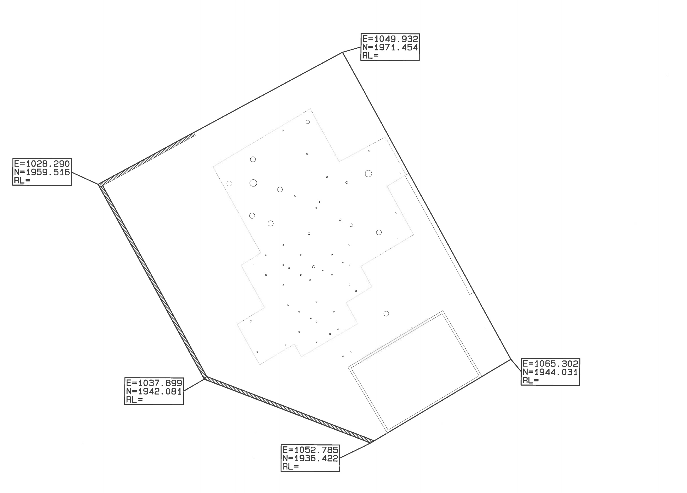
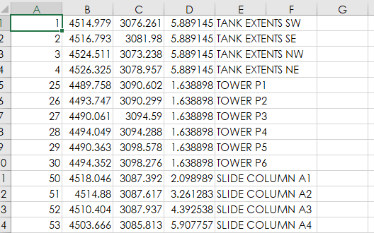
Example of what we get, these points will be marked on the ground so I could use one to locate the base over and then check the others before replacing any other marks that are missing.
the way you are describing it is pretty much what we call localization. It is the effort of sitting on a point and checking into known points and then using them as a network to prorate the error throughout. Unfortunately reach does not currently have localization, but the field genius program mentioned above does and is really not all that expensive if this is a serious business tool. The reach units will definitely get you close enough. The guys should be pulling tape once they have points to square off from anyhow.
Ok so I have had a day playing with this. I bought two reach rs+, poles, a windows tablet. Anyway I can do surveys using reach view, but using fieldgenius I think I’m missing something.
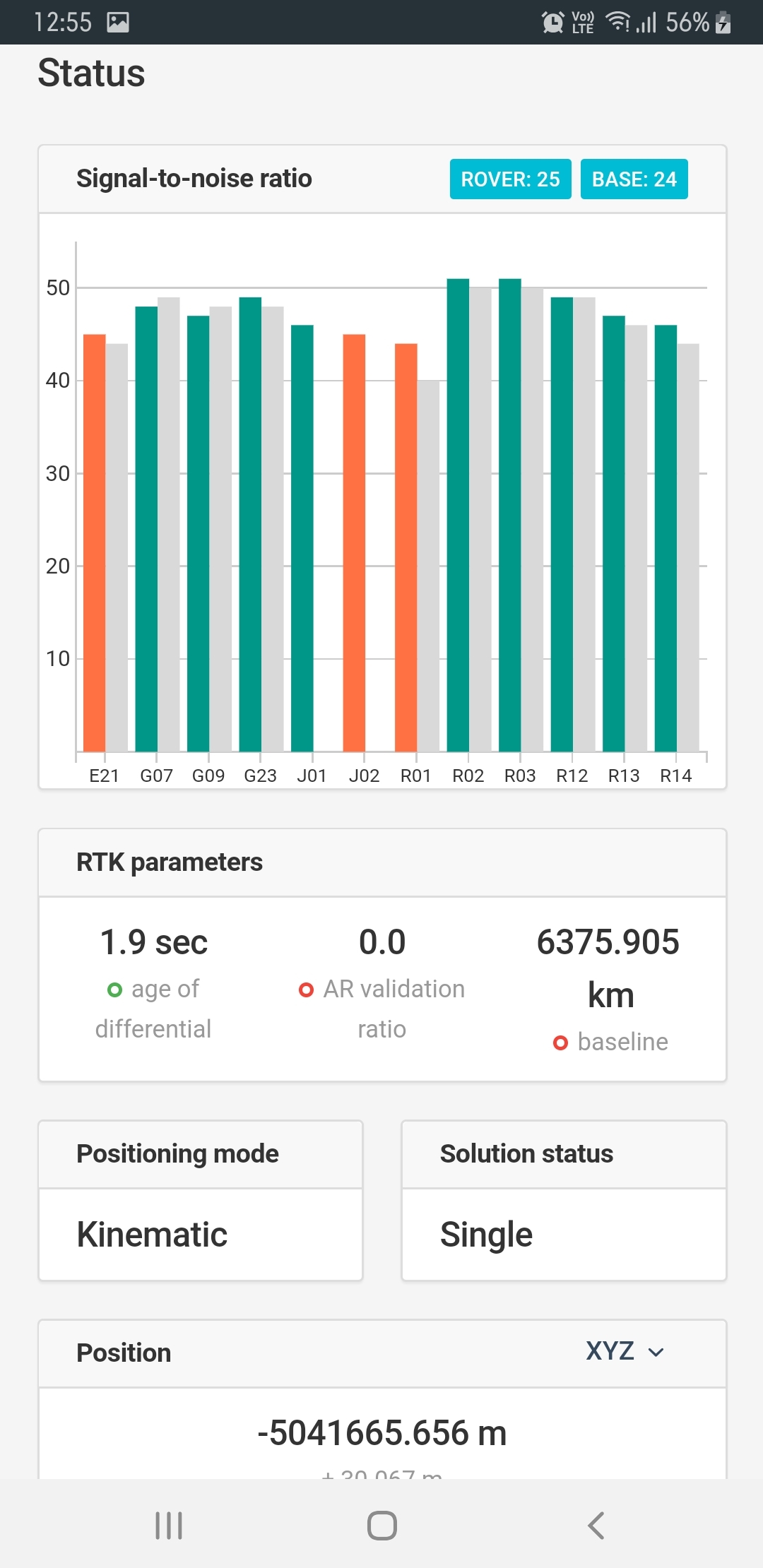
My cad file uses x y z and when I use reach view to tell the base station its coordinates the rover says it is 65000km away.
Do I need to connect fieldgenius to the base unit to set its coordinates and not use reach view other than to set up the lora etc?
Hi @murraystuartbooth, If you have FieldGenius you are correct that all you would use Reachview for is to configure the receivers. I had the same problem when the coordinates entered into Reachview were either incorrect or in a format that was not aligned with Reachview’s requirements.
Awesome thanks for that. Fieldgenius complained about the lat and long being invalid so I guess that’s it.
There’s a note on fieldgenius help saying the reach is not able to be used with normal base and rover rtk, I’m sure that’s out of date now, hopefully…
You need to use GNSS Local Transformation (localization or site calibration) under Survey Tools under the Plumb Bob icon. You find a physical control point to start, set your ROVER on it, take a measurement and basically matching these (2) measurements as one bringing them together to add more control points and to start staking out the design points or collect more etc. You may need to study RTS also. Rotate, Translate & Scale.
In Fieldgenius, you do not need to do anything with base. Just the rover.
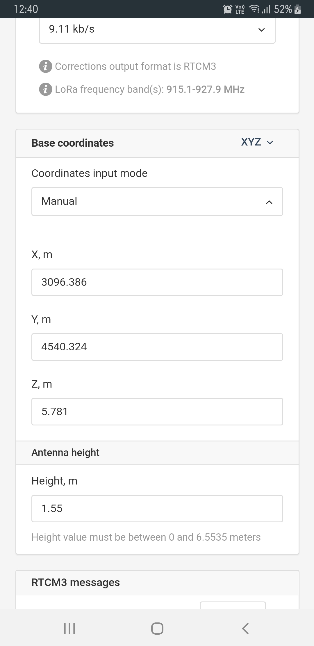
You use ReachView to set up your base which can be anywhere, the rover is RELATIVE to the base. So you may need to tie to a KNOWN published or surveyed point and set base on that manually along with antenna height. All in WGS84 or ellipsoid height lat long coords. You may need to load a GEOID for the region also if working with a benchmark elevation such as NAV88 and orthometric height.
But first, you need to make sure your project file is set up correctly to start. You need to make sure your units and coordinate systems are correct.
What region of the world are you in and the project in? This will determine your UTM region zone, or state plane if you desire this. You probably don’t need to check curvature and refraction correction unless a very very large area surveying where the curvature of the earth starts impacting things which I doubt by your drawing.
I see your CAD plan example is using Eastings (X) and Northings (Y). What are the RL referring to? Elevation??? Whomever created that drawing may have or may not have designed withing the correct coordinate system? If so, then you need to match their coord system they used.
It’s kind of like a geo referenced drawing which uses LLH Latitude Longitude Height coords and elev. (Ellipsoid height). But instead it uses UTM Easting Northing coords and either ellipsoid height or orthometric height determined by GEOID loaded for the region.
You can find all this help at MicroSurvey’s Support Desk site. Movies and help galore.
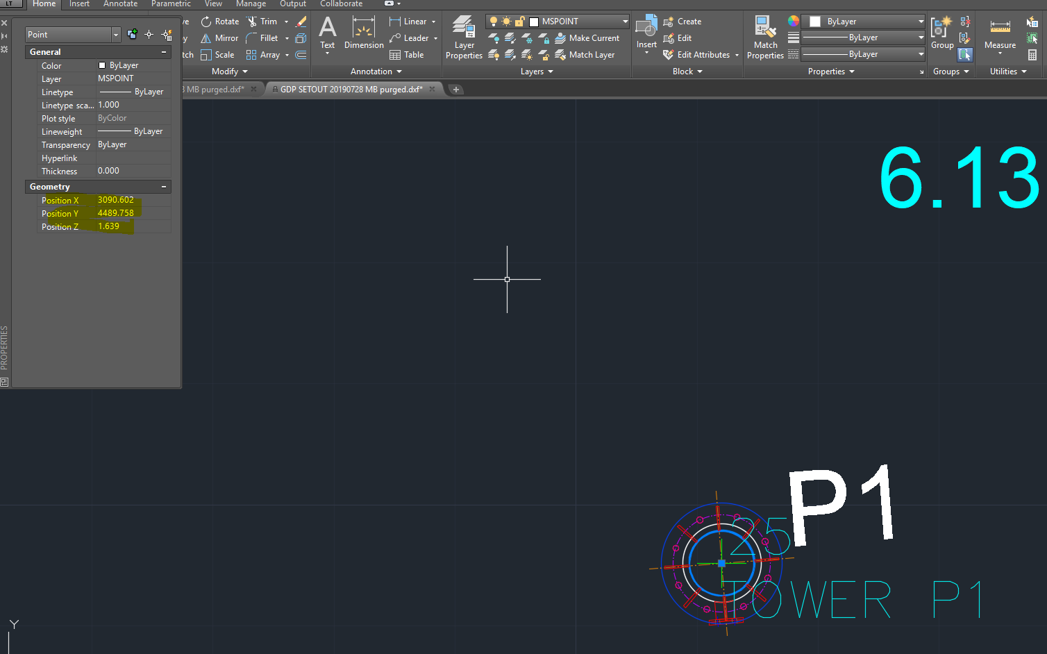
Thanks for your generous reply Tim. That example isn’t the one I was using. The one I am using has x y z heights for all points which I got into fieldgenius via microsurvey transfer along with named points for the setout. The surveyor gave me a bunch of gps marks to localise to including the x y z for each.
So I set up the base station over one of the marks, then used reachview base station mode to tell it where it is x y z. This is the part that doesn’t seem to work as it then shows the distance to my rover as 6000km away. This is the only part I am stuck on at the moment.
Since your using FieldGenius, you might want to stick with a consistent “standard” coordinate system such as LLH or UTM or state plane coordinates.
I don’t think FG has a ECEF or XYZ coordinate system to work in? You may need to contact MicroSurvey if so?
If you stick with the coord systems mentioned you can follow the GNSS Local Transformation to localize and do what you need. Otherwise, your gonna have to figure things out differently using your system.
Your CAD files need to also match the coordinate system since your using MicroSurveyCAD etc. Or at least the coord systems mentioned.
That’s the thing- they have their own reference for the site and all their drawings use that. I guess I assumed that would be fine because it is the same reference for my cad and points database.