


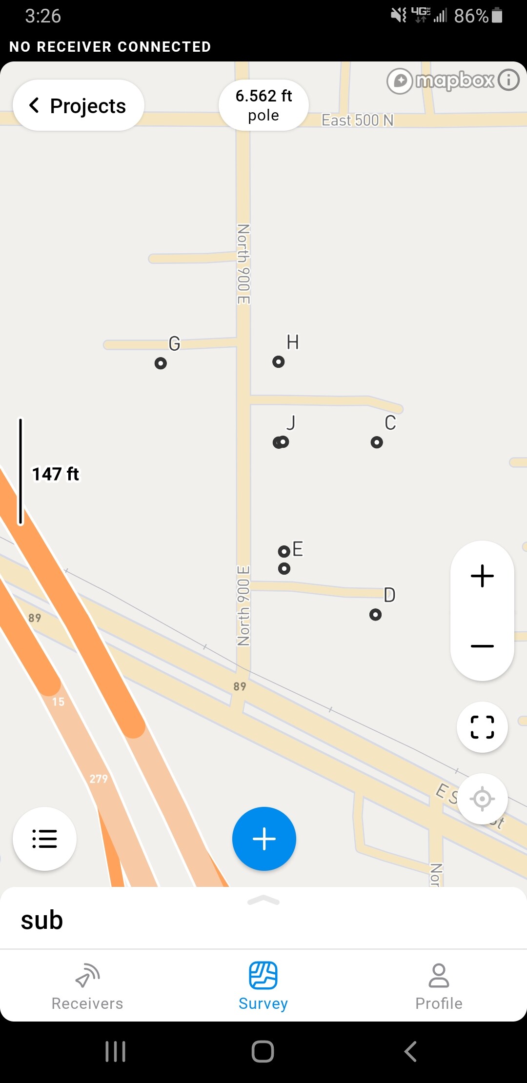
I have uploaded a file with property corners in State Plane Coordinates (Utah Central 32043). When viewing the points in emlid they do not show up in the correct location. They are east about 100 feet of where they should be. Is this a concern? When I go to stake them will they be in the correct location? I am assuming the base map is in a different projection than NAD27?
You probably want to run NAD83 unless the control you are coming from is reported as NAD27. Is it directly northeast of southwest? It might be a scale factor issue.
The control is reported in NAD27. I do have NAD83 for the section corner that is used as a tie but the surveyed points are all reported in NAD27. I have used CORSPCON to convert the points to NAD83 but they do not align when put into a GIS. Here is a screen shot from emlid. All of the points should be on the west side of the road. The NS distance may be correct.
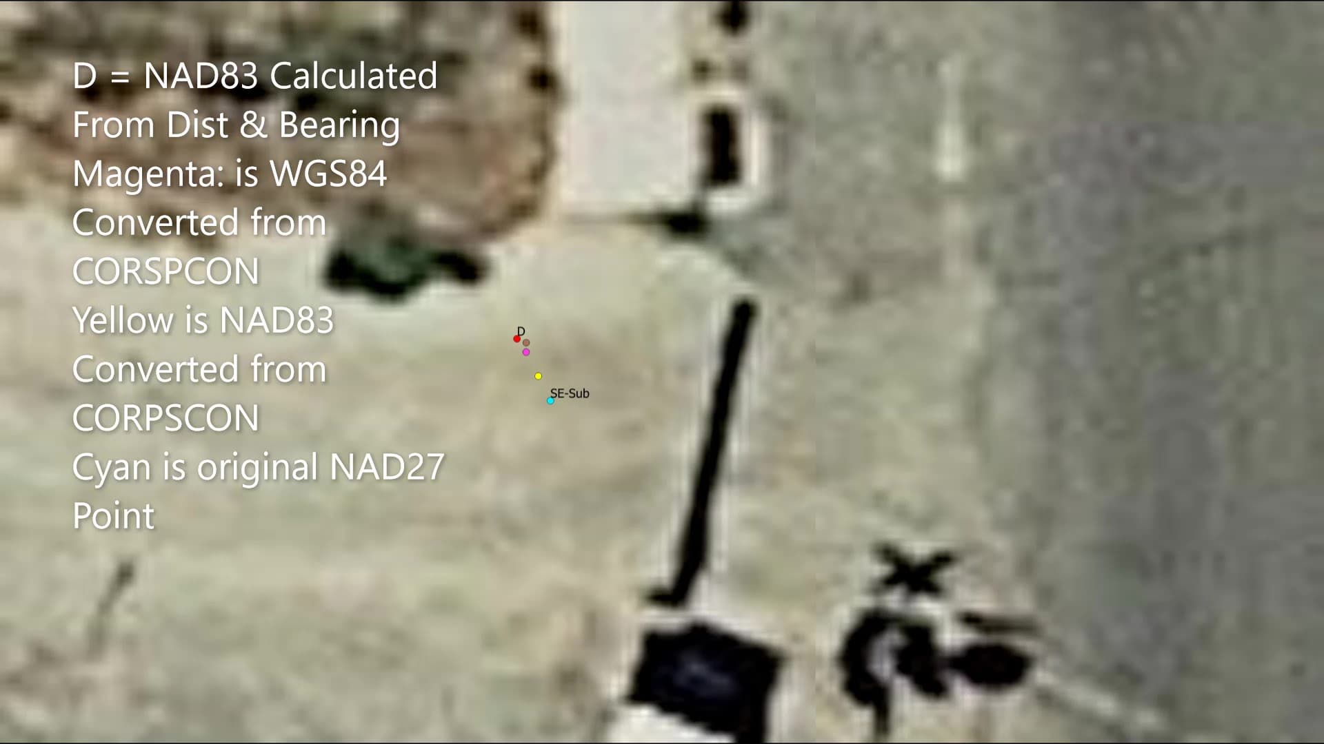
The jpeg is image is of the GIS showing relationship between all projected points. The aerial image is WGS84 (ESPG: 4326.
1 Like
Hi Mark,
If you converted all your points to NAD83, you should use a project’s coordinate system based on NAD83. However, if I got it right, you use NAD27 / Utah Central (EPSG:32043). It may be worth checking NAD83 / Utah Central (EPSG:32143) for your project. In any case, please keep me in the loop if it helped you.
As for the base map, its position is projected on the fly to match your data.
1 Like
I used EPSG:32043 for NAD 27. That is how I set up the emlid survey in the app. I sent a screen shot of the points and they are East of where they should be. Do I need to wait until I am in the field and connected to the Base for the points to display correctly?
The section corner tie sheet provides the following:
Horizontal Datum NAD_83 (2011) Utah Central Zone
Vertical Datum NAVD88 (Computed using GEOID18)
Data collected using Utah Turn GPS
NAD_83 (2011) State Plane Coordinates :
N = 7,311,566.47 US Survey Feet
E = 1,548,446.98 US Survey Feet
Ortho Height: 4,566.84 (Geiod 18)
And for NAD 27:
AD_27 State Plane Coordinates :
N = 749,901.02 Feet
E = 1,908,241.64 Feet
The surveyor’s plat uses NAD 27 coordinates, so that is what I thought I should used.
I recalculated all the points using the NAD 83 tie information and the surveyor’s bearing and distances. I used the EPSG: 6625 (NAD83(2011) / Utah Central (ftUS)). Using this the points are 3 ft north and about of 1 ft west of the NAD 27 points. I will try the NAD 83 (E{SG"21143) to see how they align.
1 Like
Something looks wrong with the coordinates to me. Why would a slightly different projection be 6.60M out on Y and 360K on X?
1 Like
Hi Mark,
If the project coordinate system is set correctly for points, they should be displayed in the right place as soon as you import them into ReachView 3.
About this:
Can you clarify how you compare the position of the points? Do you import them into the same project in ReachView 3?
And one more thing, I suggested the NAD83 / Utah Central (EPSG:32143) because I thought you have coordinates in meters. However, since you have point coordinates in feet, you need to set a suitable coordinate system for that.
I brought the point files into QGIS.
I have recalculated the points and am going to bring them into emlid again.
The survey plat had coordinates for subdivision corners posted (NAD 27 US Ft) as well as the bearings and distances for all points. There were 2 distances for each bearing which I am assuming that one was the calculated distance and the other distance in parenthesis was the actual distance measured. I ran the calculations for both. The “actual” distances aligned with the stated coordinates within 1/2 an inch so these are the points I plan to use to stake out the property corners. When I used the NAD 83 coordinates for the section corner and the NAD 83 USFt. datum to calculate the bearings and distances these points are about 3 ft NW of the NAD 27 points in QGIS.
Hi Mark,
Thanks for the details! Can you share these point files with us: the original file in NAD27 and the point file converted to NAD83? I want to check them. It can help me to analyze your data correctly.
In case these files contain some sensitive info, you can send them to support@emlid.com.
Hi guys,
I got Mark’s files. However, for now, I need a little more time to figure out what might be wrong. Just keeping you posted!
Hi Mark,
The files you shared helped me understand what you are talking about. I saw that the points in NAD27 are indeed displayed in the wrong place in ReachView 3. However, when I import your converted point file in a project in NAD83(2011) / Utah Central (ftUS) (EPSG: 6625), the points seem to be displayed as they should be. This seems quite weird, and we are now investigating if it may be due to the display of the base map.
Did you try to stake out the point you used as a tie? Was it in the correct place? It may shed some light on this issue.
I have not been out because it has been too cold. I hope to try to stake out the point within the next two weeks.
Hi Mark,
Oh, I understand. It’s pretty cold in our area right now, too. So, if you can test it, just let me know. It’d help to check if the points are not where they should be or if it’s a display issue.
One more question, can you please clarify who provided you with these points in NAD27? I just want to confirm that there is no issue with the source data.
They came from a survey plat. I have attached the plat and the section corner tie sheet.
9-5s-1e-slbm.pdf (693.5 KB)
Plat-COGO-Test.pdf (1.8 MB)
Hi Mark,
Thanks for the files! I’ll pass them to our team for further investigation. Please also keep me posted on you progress.
Hi Mark,
How is your work going? Did you have a chance to stake out your points?
Meanwhile, we found out that the background is indeed shown with a shift in NAD27 in ReachView 3. Such cases are very rare and only affect some old coordinate systems such as NAD27. It’s only a matter of display, so the positions of the points should be correct.
If this is appropriate for your application, you can also use NAD83(2011) / Utah Central (ftUS) (EPSG: 6625) for points converted to NAD83(2011). This setup uses the newest NAD83(2011) datum, and the points are displayed correctly.
I have not been able to get out. It has not been above freezing here.
Maybe this week I will try.
Thank you for investigating this. I have converted the points to NAD83(2011). However when I plot them in QGIS they do not align with the NAD27 (few inches off). The original survey was done in NAD27 so I think I need to use it. I am planning to also stake out using the NAD83(2011) and see how close they are. The QGIS base map is from google earth so that could be why the 2 projections do not align. I know there are issues with the WGS84 google mactator projection.
Thanks again for your help with this. I will let you know how the stake out goes.
This is probably less a projection/datum issue and more a georeference issue. Depending on how rural the area is, georeference of the aerial imagery can be meters off. In built up areas, more work is put on referencing and orthorectifying correctly but it gets pretty inaccurate the further you go from urban centers.
Try adding different sources like these:
USGS base orthomosaïc (WMTS): https://basemap.nationalmap.gov/arcgis/rest/services/USGSImageryOnly/MapServer/WMTS/1.0.0/WMTSCapabilities.xml
ESRI World Imagery (REST): https://services.arcgisonline.com/ArcGIS/rest/services/World_Imagery/MapServer
You might find that the georeference is much better on these. In any case, you shouldn’t be looking at aerial imagery to evaluate the accuracy of your surveys. This is like using a sewing tape measure to verify a vernier caliper measurement.
1 Like
Thank you for your help with this.
Your comparison to a sewing tape to vernier caliper is very helpful.
I think this explains many things for me. I use UAV imagery with pixel resolutions of 4 cm or better with ground control from emlid receivers. When overlay these orthomosaic images on 6" aerial base map imagery they don’t align perfectly. Am I correct in saying that because of their natures they really can’t be aligned?
Mostly yes. Because of how large an area the mosaïcs cover, some generalization has to be done.
If your GCP survey is done correctly and is verified good, then I’d trust the drone mosaïc over a wider-area dataset any day.
1 Like