I am trying to link the old Reach RS and the new Reach M+ with the module RFD.
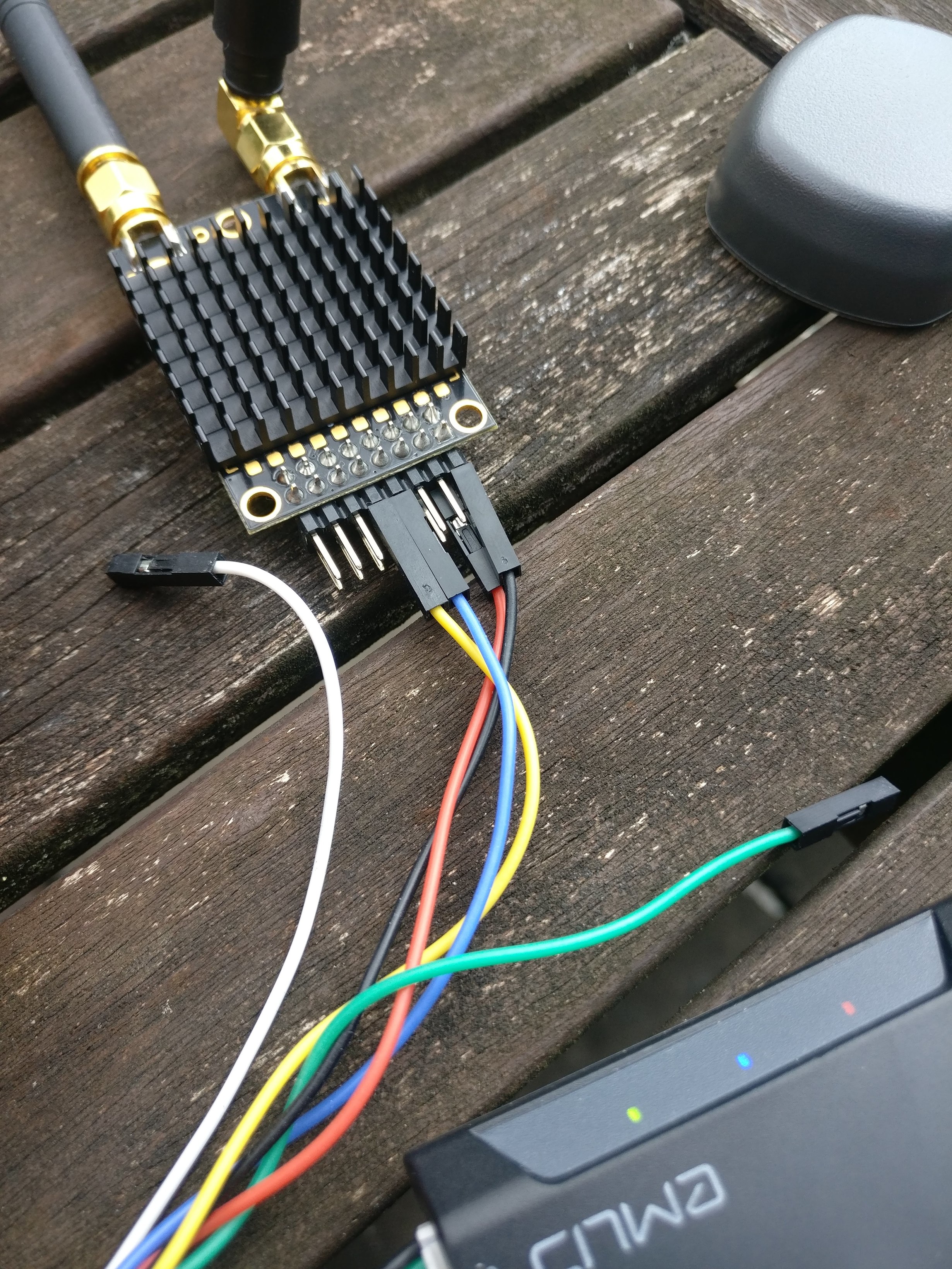
I bought this module: RFD 868x Long Range Telemetry Modem Bundle, which is the one suggest to use to link these two device together and I have connected with the JST cables on the M+.
To confirm the functionality of the link between the the RFD radios I have done this:
Connect the RFD to M+
Set output position to UART
Connect second RFD on my pc
Open serial port
And after that, I was getting NMEA packages.
After confirmed that, I have changed on the Reach M+ to receive the RTK from the serial and disable the position output.
I have connected via OTG the second RFD to the Reach RS and configured the base output to USB OTG.
I have upgraded both of the devices to the latest ( of today ) version but the result is the same, I dont see the Reach M+ getting the RTK messages via UART.
What did I do wrong? Has anybody attempted this setup before?
M+UART to RFD868 --over-the-air–> RFD868x to USB-FTDI to PC
Try sending data the same way this time:
M+ base output --> PC (see RTCM3 data)
Now swap PC for Reach RS and set up base correction input.
See if you get base corrections. If that works, then maybe you are on v2 firmware and there is some point-to-multipoint issue? If you are on v1 firmware, then if it works one way then it should work the other.
Unfortunately it didnt work. I can receive the the RTCM messages but using the arduino serial I can really understand if it is correct.
Possibly the RTCM messages are not human readable therefore the system work but for some reason the Reach M+ is not accepting them.
Interesting thing is that if I set the M+ as BASE and RS as ROVER, it actually works.
One other odd thing on the M+ is that when I set BASE MODE off, it keeps averaging the position and seems like it doesn’t turn off the base mode, maybe there is a bug in the software?
Never mind, I solved it, it was odd that OUT was working and IN didnt.
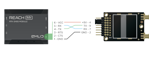
So I re-read the doc which I correctly followed but interessing thing is that the DOC is wrong, the actually RX and TX cables are BLUE and YELLOW not BLUE and GREEN!