We purchased an RS2+ the Reach Rover-RX recently. However, it’s come to my attention that you could just use the rover and connect to an NTRIP and bypass the base station RS2+. We did some tests with the base station/RX combo and it was very frustrating. I went ahead and used the RX and the RS2+ separately as rovers and it appeared to work with SmartNet NTRIP. “Fix” solution was green on both devices so I’m assuming things were going well. No issues with the signal.
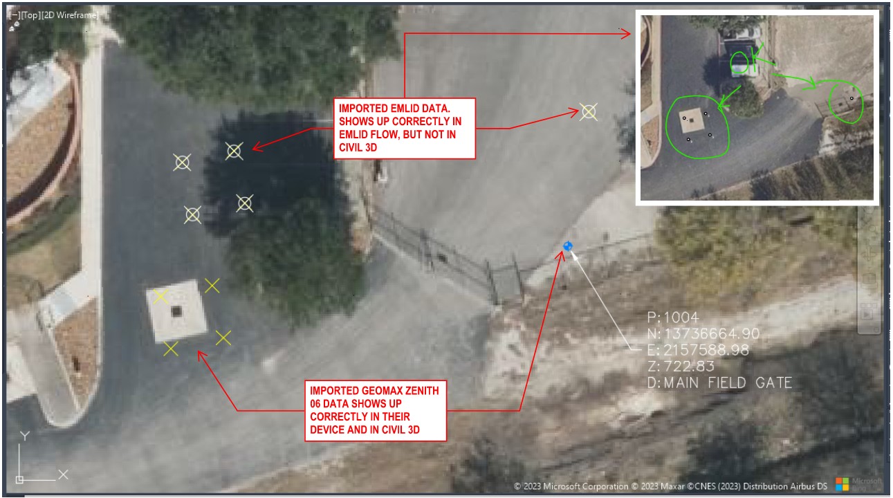
However, when I bring in the control points to Civil 3D, they are off. They do not match locations on the map from EmlidFlow. I’m attaching an image comparing the two for reference. Any thoughts? I’m scratching my head on this one.
Are you comparing results from the two different receivers or one receiver in the two different programs? If one receiver, is the N/E/U data being used the same in both programs (Civil3D/EmlidFlow) and you are just getting different locations in the displayed maps? Are both maps using a georeference ortho drone photo or are the points being overlaid onto a google/openstreetmap map? If comparing to a google map, your accuracy will vary, they just aren’t that accurate. Easy to prove, just go shoot a manhole cover by your home/office and input into google maps and you will see for yourself how far off they can be.
In the Emlid I am set to NAD 83 South Central Texas Feet, In Civil 3D I am set to NAD 83 South Central Feet. The initial image I uploaded may be confusing. I revised the image. See attached.
As an update, I used a GeoMax Zenith06 device and shot the same points. Those came in correctly in Civil3D. Set to NAD83 as well. I’m attaching those pics.
I’ve discussed with Emlid and they do not have an answer for me. If I use the Emlid Data I have to Base Shift in order to get the points aligned with the existing benchmark. I shouldn’t have to do that.
I clarified my situation with a new snapshot. I’m using the Autodesk georeference map. I know it is not exact, but these points are wayyyyyy off. It’s only with the Emlid. The other device I am using it comes in fine. It’s makes me think it’s on Emlids side. It happens with both the RS2+ and the Reach RX.
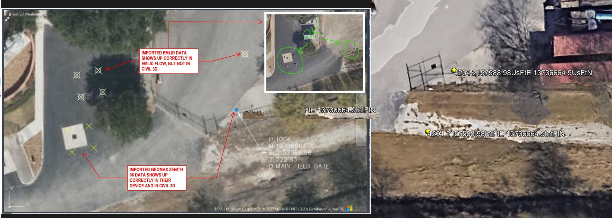
I suspect like Michael there’s a difference in using usft vs ift in the user selected projection you are using in Emlid. I doubt that the issue is in Emlid. I did the same thing and found out I had selected a different projection using usft (SC uses ift/meters in their system). There’s about three projections available in Emlid software for SC and others as well.
I will also point out that the NAD83 that is in Civil 3D is the older 2278 and the backgrounds are easily out of rotation by 5+ degrees and 10ft. You might try setting your background to NSRS 2011 to see if it aligns better with NAD83 (2011) which is EPSG 6588.
How was positioning established for the other receiver? Was there a localization?
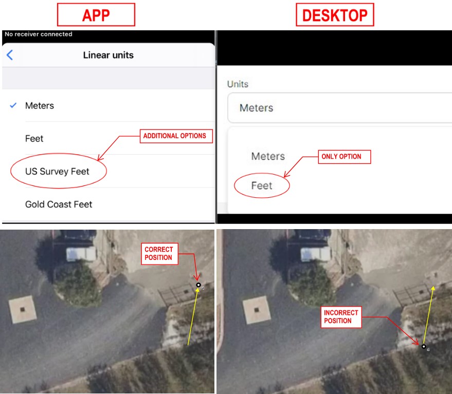
So, here’s another update. I noticed a discrepancy with the App vs Desktop. I’ve been creating projects on the desktop interface. When it comes to setting the linear units, my only options are Feet and Meters. On the App I have additional options including Survey Feet. This did cause an issue when I imported the benchmarks using “feet”. I just created a new project on the App and selected “Survey Feet”. This resolved the issue with the benchmarks in the wrong place. I believe I need to create ALL projects through the app and select Survey Feet.
Both Michael and Bryan brought up good possible reasons for the shift, so I was wondering what Michael/Bryan had brought up about Inft vs Usft, could be the possible reason. I did a conversion using Earth Point’s website in US Survey Feet and International Feet and input that into Google Earth Pro and came up with the same amount of shift as you just did.
Very very very interesting. Thanks for taking time to look at it. I’m still a novice at this stuff. I am letting Emlid know about the discrepancy in the Desktop vs App interfaces.
Someone is probably more knowledgeable than I on this but wasn’t USft deprecated for all new Surveys and Engineering projects since January 2023? The next year should be interesting figuring out what’s what now that many will be switching back.
This won’t technically happen until the new datum by NGS starts. Also many users in various states will continue to use the old NAD83 (2011) Epoch 2010.0000. Individual states can set their own units of measurement by legislation, but NGS new datum will be in ift and meters. This was the problem back when NAD83 was adopted in the early 80’s, partly because there was (and still is) no true conversion between the horizontal/vertical datums between NAD27/NAD83.
Now, NGS has the tools to convert between datums/coordinate systems with NCAT, but there’s also the issue converting between vertical datums. NCAT can’t convert between orthometric and ellipsoidal heights right now. Only orthometric to orthometric and ellipsoidal to ellipsoidal height transformations are available in NCAT.
Thanks B! I had a sneaking suspicion you’d be the one to clarify this. Unfortunately for us Contractors I have a feeling that we will be dealing with this for years and when the new datum finally comes it will get worse with a wider gamut of possible conversion and transformation issues that could occur and cause conflict between Surveying, Engineering and Construction.
Personally I wish Engineers would stop using surface coordinates in CAD for construction, at least for sitework. It is the number one cause of misalignment for us and makes a lot of the newer tech that works off grid much harder to implement than need be. This is an area where having affordable and dependable Emlid equipment has really helped. I can easily go out and collect the major monumentation on grid and create a more accurate (localized) transformation in CAD from surface to grid so that all of our equipment can operate on natural grid coordinates. The problem it then causes is on fast track projects that are constantly being re-designed and having each tech remember to and correctly perform that transformation on the new data.
Michael, I’m in construction also. Lately, it seems that we’re getting a lot of surveys in surface and not grid. We’re in this state where if we get something in surface then we stay in surface instead of altering it for all the trade partners. If we’re in grid then we stay in grid.
How do you all handle the data with your trade partners and field personnel? Thanks.
Hey Adam. Is it the Survey or the Engineered design? I find quite often that if you go and look for the original Survey control and CAD that they will be in grid but once it hit Engineering it gets scaled whether it’s an automatic program setting or just them trying to squeeze every hundredth of accuracy out of site absolute positioning. I agree with the need for surface coordinates in corridors particularly over long distances but even with those being built on the ground they get phased and built from the outside in to mitigate error. On a construction site of 100ac that tenth-thousandth of a percent means nothing but the absolute positioning that doesn’t talk to all the positioning tech we use that causes heartache.
Everything we do goes back to grid no matter where it was when we got it. First thing we do is verify the field control and shoot it with an RTK network. Then a localization file is created in CAD which helps the localization done by layout match grid and you always have a source of truth that can’t be argued with but can also be recreated instantly.
I have to convert surface to grid and vice versa on probably 90% of the jobs we have. Only ran into isft vs usft once the difference was about 21 feet. I ended up creating a spreadsheet with a formula that converts the coordinates for me, just put in E N and the scale factor and it spits out what I need.
You have Civil 3D right? Just XREF the data in and plug the scale factor into properties. I found that works better than plugging it into the XREF dialog box. Not sure why but it just seems to be more consistent. Plus you can actively fudge a ten-hundred thousandth if needed.
No, Agtek Gradeworks. There’s a way to adjust for scale factor in there for contours. For ground control I get from our survey folks I use my spreadsheet. There’s probably an easier way to do it I just don’t know it
Yeah, I am lazy and avoid Excel at all costs. I always have the points in CAD anyways so I just XREF the file into the layout CAD and plug in the ScF. That way I have a visual from my last ortho as well for backsight before I get down the pipeline and find an F up like I did one time… and didn’t see it until I processed Gradework and imported the contours into another file.