Detailed problem description. How does observed behavior differ from the expected one?
Your step by step actions.
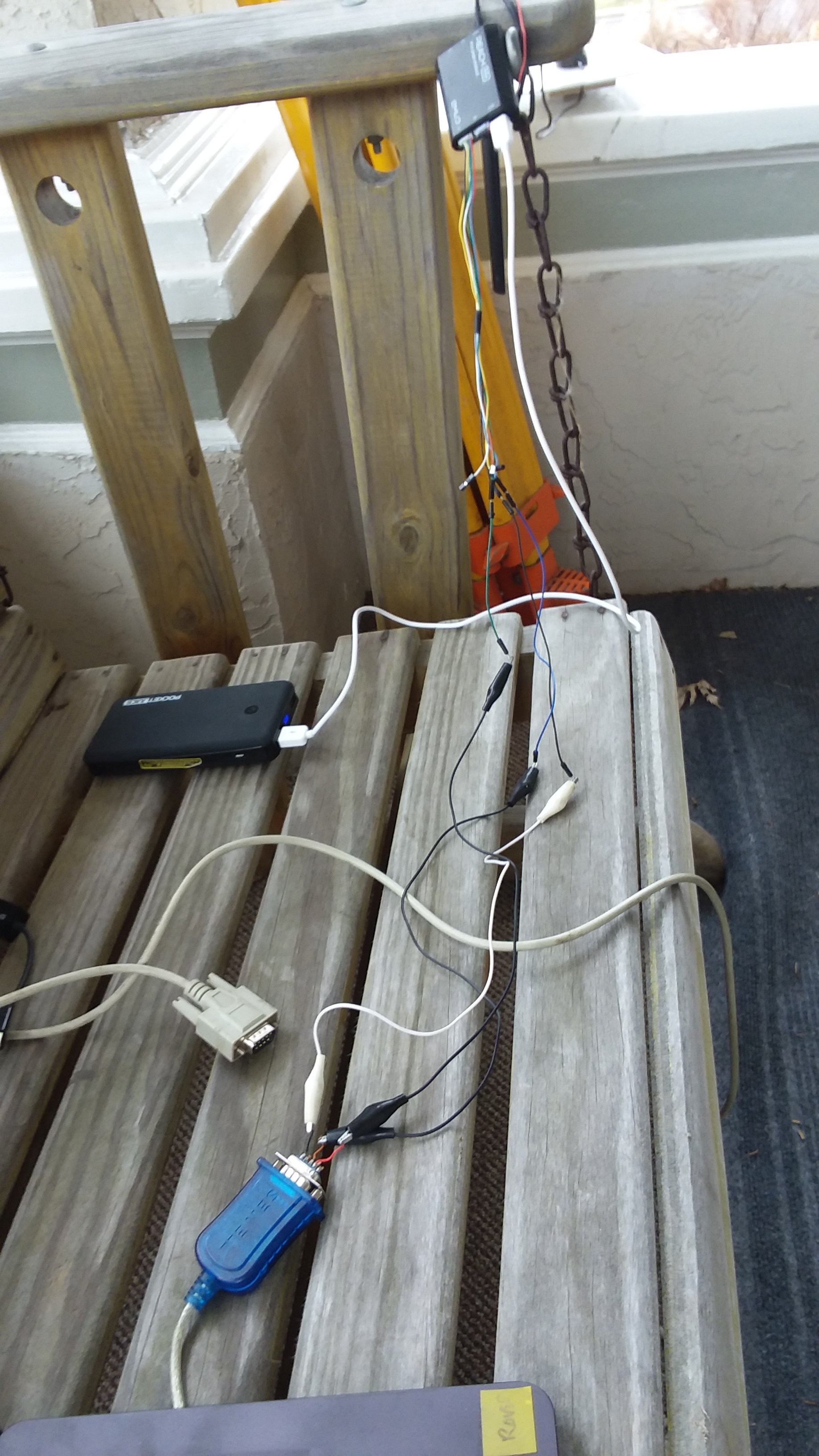
Picture of the setup and connection scheme.
Specify the exact make and model of the hardware you are integrating.
I want to use my new Reach M+ to send NMEA position information to a ground penetrating radar system.
I’m running the latest stable version of Reachview (2.16.2) and believe the firmware on the unit is current I only received it recently and I updated everything when I brought it on line. I wish I had made a note of the firmware number because I can’t seem to figure out how to find out that information from Reachview!!!
I have made up a basic serial cable (TX, RX and Ground) and bought a 6 pin JST-GH connector connecting to pins 1, 4,5 which the on-line docs tell me are Ground, TX and RX. I confirmed continuity for each line with a meter.
When I connect the cable I made up to Reach M+ (Connection S1) and I configure Position output in Reachview to UART, 9600 baud, NMEA, the terminal program (mttty) - configured with the same com port setting (9600 baud 8-N-1) shows activity but not what I expect ie NMEA strings - its just gibberish.
I have checked the forum and I suspect the problem is a ground problem although my continuity tests suggested that my cable is good. Is there something I’ve forgotten to do? Do I need more that the 3 pins I connected?
If you look in the upper right corner you’ll see it lists the version of Reachview NOT the firmware version> I looked everywhere in Reachview and couldn’t see anything listing the installed firmware.
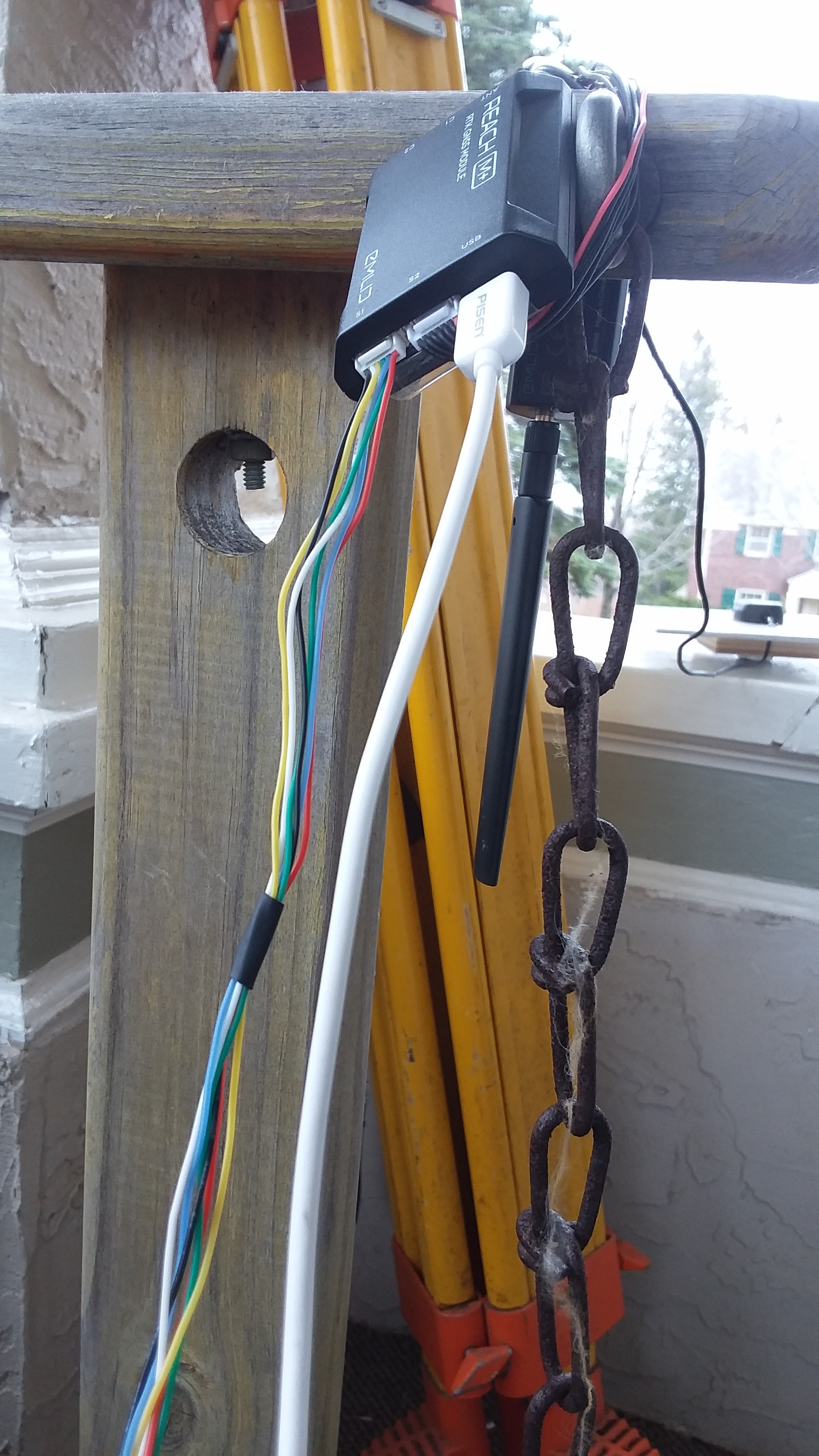
This shows the wiring I’ve made up. It connects via a DB-9 connection to a USB-serial adapter. I have confirmed that the USB-serial adapter is working correctly. I connected pins 1,4 and 5 on the JST-GH plug to pins 2,3,5 on the DB-9. One thing that does puzzle me is the pin order on the JST-GH connector. If I understand the emlid documentation correctly, pin 1 on the connection is the one closest to the edge of the M+. So if you were to look at the end where S1, S2 and USB connections are, pin 1 on the S1 connector is the leftmost pin on the S1 connection. According to the docs pin 1 is Ground, the connected ribbon is colored red - which is unusual (I think!) because I think the red colored wire on the ribbon (all else are black) is usually (often?) the +5V line. I have wired that line under the assumption that its the ground. If its actually an inactive +5V (I power the Reach M+ via the USB), I have no ground which would explain why my output on my terminal is gibberish.
This is the output I get on my terminal program (Mttty) - I don’t use Putty to look at serial input. You’ll see that baud rate etc at the top of the image. This matches the position output settings in Reachview shown above.
I suspect I have the pin order backwards on S1. I look forward to hearing what you have to say.
Agreed - the pictures aren’t the best. I don’t believe they would have changed anything though. The information in the upper right corner of the Reachview app shows which version of Reachview is running - the most recent stable version. The photo of the connection simply shows the cable which as I described in my text has three connections, Ground (1), TX and RX (4 and 5). As required TX connects to RX and RX to TX (on the GPS and on the connection to the computer). The photo of the output of the terminal emulator (Mttty) shows the gibberish I’m getting. It also confirms that the settings on the COM port match those set in the position output tab in Reachview.
I am coming around to the idea that the problem lies in how I’ve interpreted the pin assignment on the JST-GH connection for S1 on the Reach M+. I plan on checking the out put using the 6 pin cabled connection that comes with the device. To that end can you confirm that
Ground = pin 1 connected to the black wire
TX = pin 4 connected to the green wire
RX = pin 5 connected to the blue wire.
The RX and TX connections connect to their complement (ie TX > RX and RX > TX) on the other end of the cable connected to the serial connection on the computer.
This massive time delay getting tech support really is a headache!
May I ask you to re-upload photos? As Christian said, they aren’t shown at all.
The pictures are usually of great help, so it’d be great to see them, as now it’s hard to see where is the issue.
I will send you something later today. However, in the interest of moving things forward (given the huge time difference between our locations), could you confirm my understanding of the physical position of the key pins on S1 in particular the ground pin (#1) - specifically is it located all the way to the left if you look at the side of the case with S1, S2 and the USB connection?
Currently I only have ground, rx, tx connected to anything.
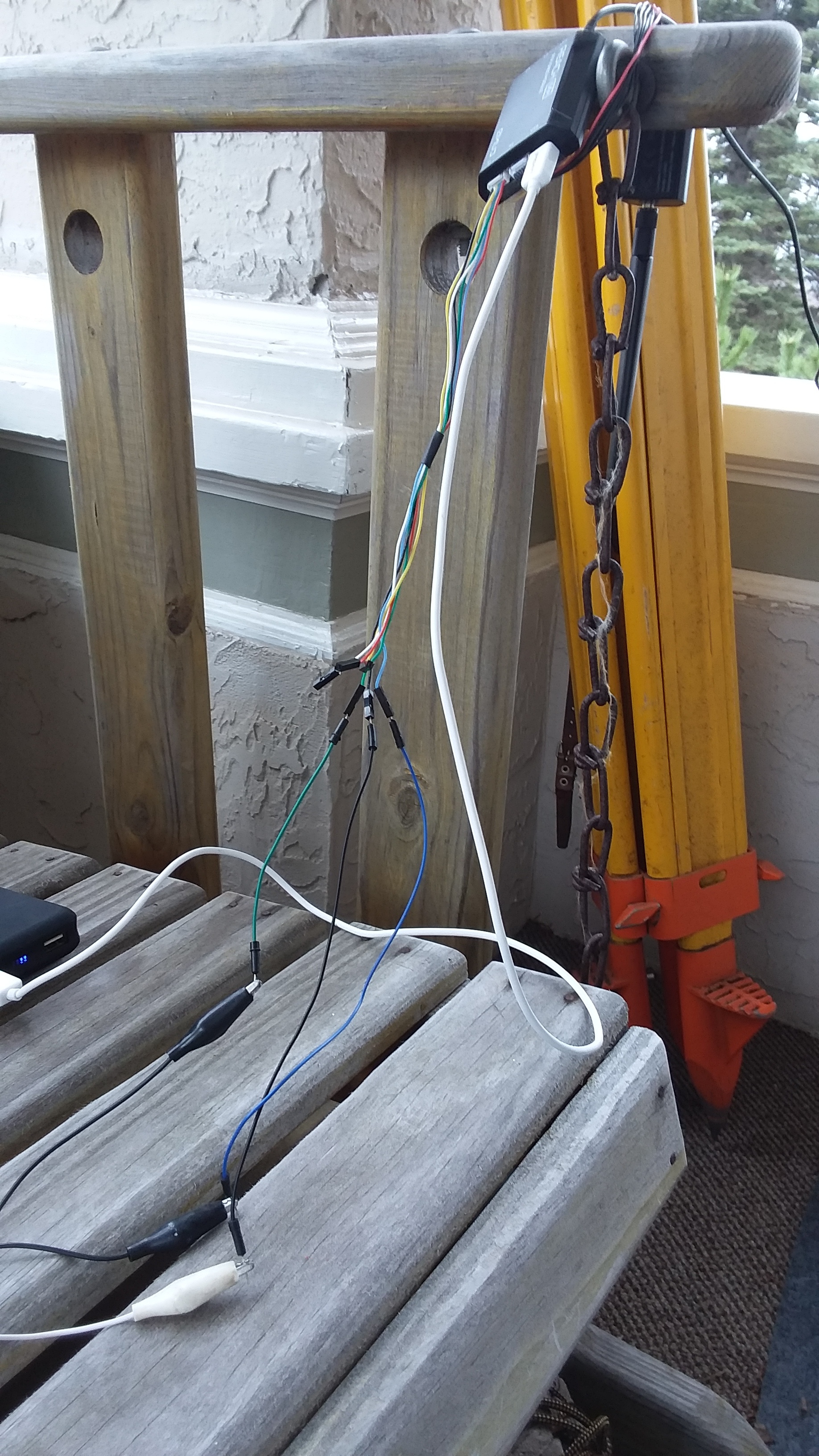
The first three show the wiring harness I made up using the 6 pin JST-GH connector that is included with the Reach M+. One shows the entire harness and the other two show closeups of different parts. I used three pins ground (1) , TX (4) and RX (5). These are connected to black, green and blue wires on the supplied plug. I connected these via jumper wires and crocodile clips to a DB-9 RS232 plug.
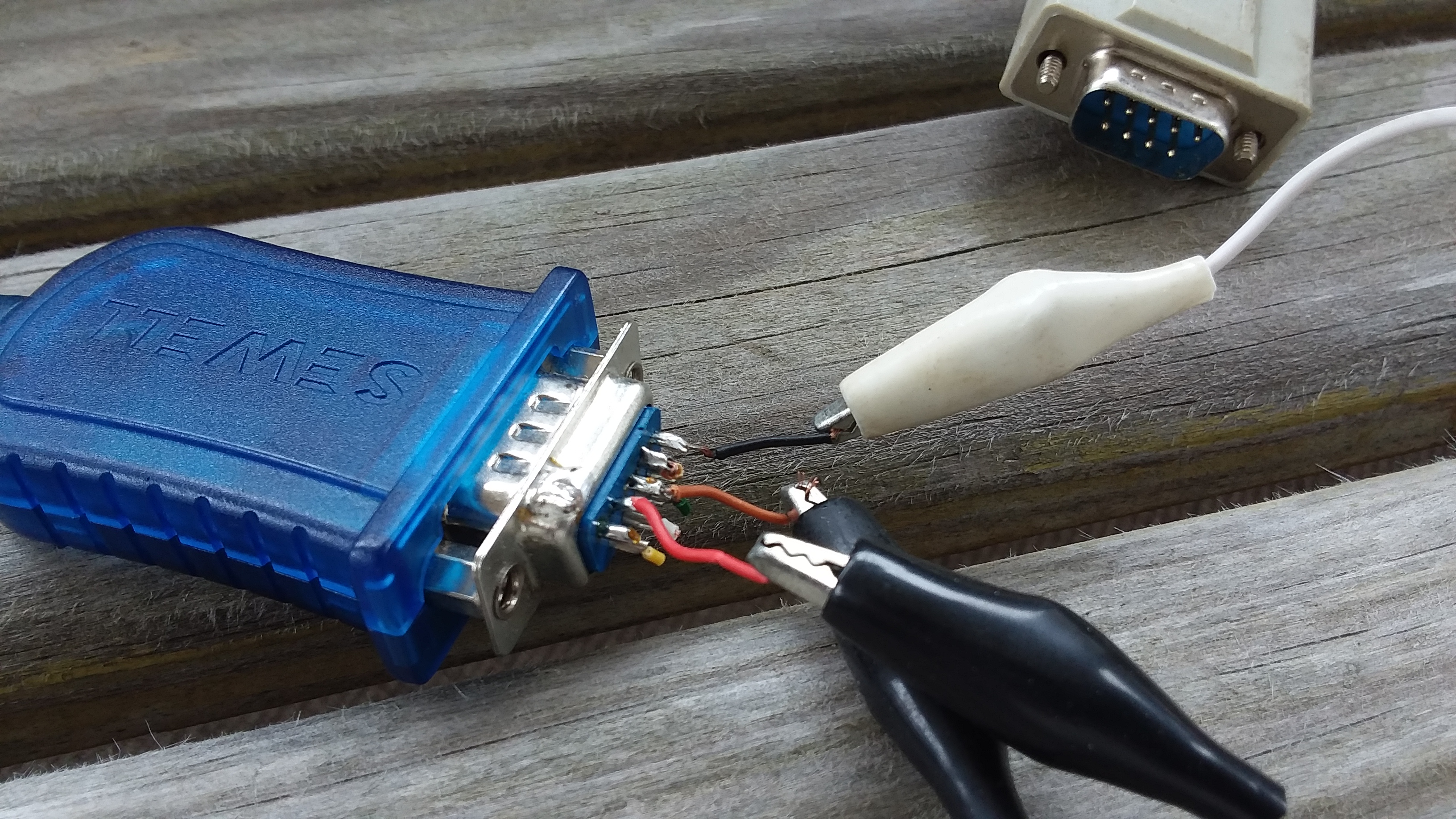
The next picture shows the back of the DB-9 plug. The ground connects tp pin 5 (via the white wire) and RX and TX connect to pins 2 and 3 on the DB-9. I made sure to connect TX on the Emlid to RX on the DB-9 and similarly RX (Emlid) to TX on the DB-9. I made sure to check the continuity of the wires with a meter.
The next image shows my laptop screen. The devmgmt tool is open on the left side of the screen showing that COM 13 has been assigned to the USB-Serial adapter that is connected to the DB-9. The terminal emulator I use to examine serial input, Mttty, is shown on the righthand side. At the top of window the COM port settings for COM 13 are shown. Below it is listed the garbage coming over the connection. This setup was previously tested with another GPS serial feed which correctly displayed the NMEA messages generated by that device.
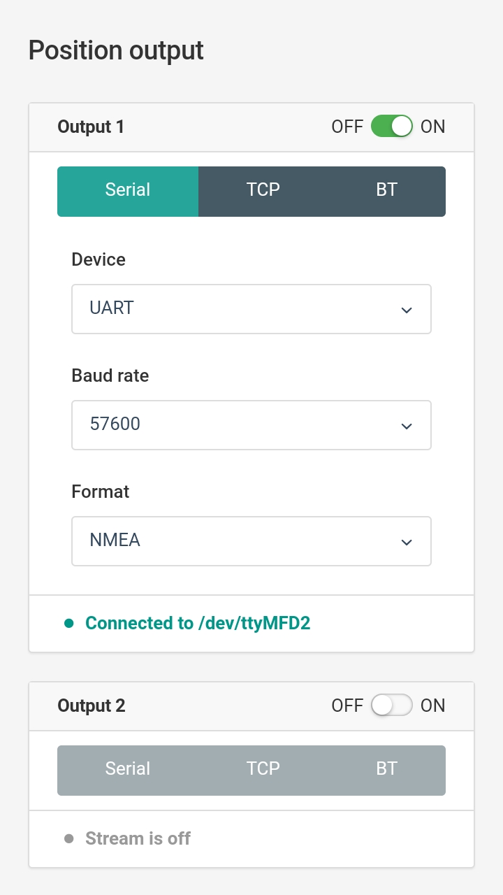
Next are two screenshots from Reachview which is running on my Android cell phone. The first shows the settings on the Position Output screen. You can see that the baud rate of the UART is set to the same value (57600) that is shown on the Mttty window displayed on my laptop.
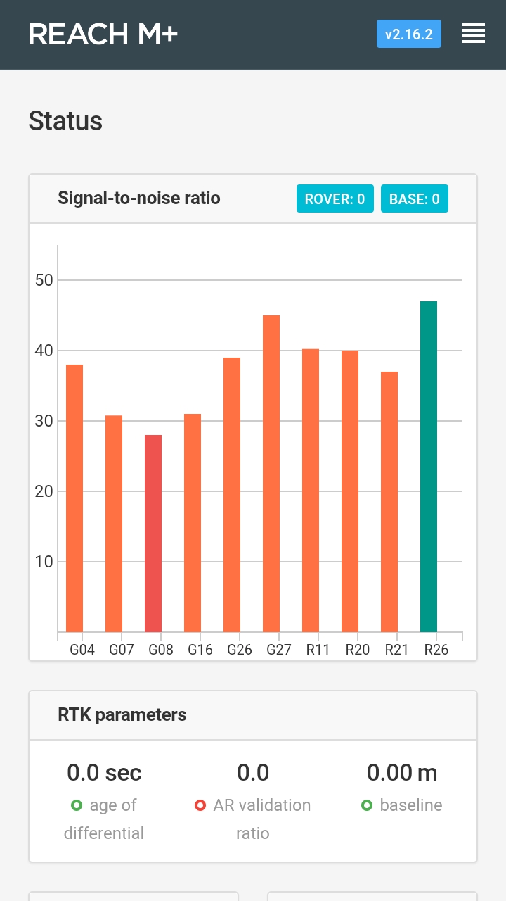
The last screenshot shows the Status page in Reachview. This shows the version of Reachview in the upper right corner of the screen NOT the firmware version. Where in Reachview is this information listed?
I noticed that you connected Reach S1 pins directly to DB-9 plug. DB-9 provides the RS-232 interface, while Reach M+ S1 port is UART. You need a UART to RS-232 converter to make it work.
ReachView software runs directly on Reach device, and v2.16.2 is the firmware version.
Android and iOS apps just allow getting access to ReachView software.
In other words, ReachView version is the firmware version.
I’m only testing the connection with a PC. Once its working properly I’ll be connecting to another device that needs a serial connection. Thanks for sorting this out. I’ve ordered a converter which should fix the problem. I will close this support request once I confirm that everything is working properly.