RTK-setup with two 3DR-radios

Dear List

I have a comprehension questions about the RTK-Setup of two old REACH-modules.

Situation:

  • Two REACH-modules (Base and Rover)
  • Two 3DR-radios (each with 1 DF13 plug and 1 USB-mini)
  • Power-supply of both with USB-Powerbank

I was able to receive the RTK-correction through WiFi from the Base to the Rover. Works perfectly.

Desired setup:

Receiving the RTK-correction by using the 3DR-radios.

Current setup:

  • Base powered by USB and radio connected by DF13.
  • Rover powered by USB and radio connected by DF13.

Both radios have identical settings (baud-rate and net-id). The setting of the baud-rate is set correctly at the REACH-module.

Problem:

No RTK-correction is received by the rover.

Question:

  • Is this setup correct or not?
  • Do I have to connect the radio of the Base with a USB-mini and the OGT-cable?
  • Any hints about the setup?

Looking forward to any hints and thank you very much in advance.

Best regards,
Yvo

Hi @Yvo_Weidmann,

  • Is this setup correct or not?

Could you please provide us with photos of your hardware setup? This information enables me to troubleshoot the issue.

  • Do I have to connect the radio of the Base with a USB-mini and the OTG-cable?

You should connect the radio to the Reach Module either with USB or DF13 cable. Please, cross-check the pinout from our docs.

Also, may I ask you a couple of questions? Which baud rate do you specify in ReachView and which baud rate does your radio support?

Hi @artem.fomenko

Thank you very much for the quick replay and the link. Personally, I have the impression, that I followed the pinout and description.

Here, as requested, the two settings of the BaseStation and the Rover in ReachView:


And the two hardware-setups of the BaseStation and the Rover (red box = BaseStation, green box = rover):


I connected both with the DF13 at the plug to the left of the USB-plug.

Regarding your questions:

  • The baud-rate is set to 57’600 in the ReachView-settings
  • Both radions are set to a baud-rate of 57’600

Looking forward to any hints.

Cheers and a good start into the new week,
Yvo

Hi @Yvo_Weidmann

Sorry for the delayed response.

Could you specify how powerful is the USB outlet of your power banks? There might be some issues if you are using 5V 1A output since only the radio takes half of that power as far as I see from the datasheet.

Also, had you tried substituting the radios? I don’t see any LEDs blinking, maybe that is related to the power supply case, which I had described above, however, it could be the hardware issues of the radios.

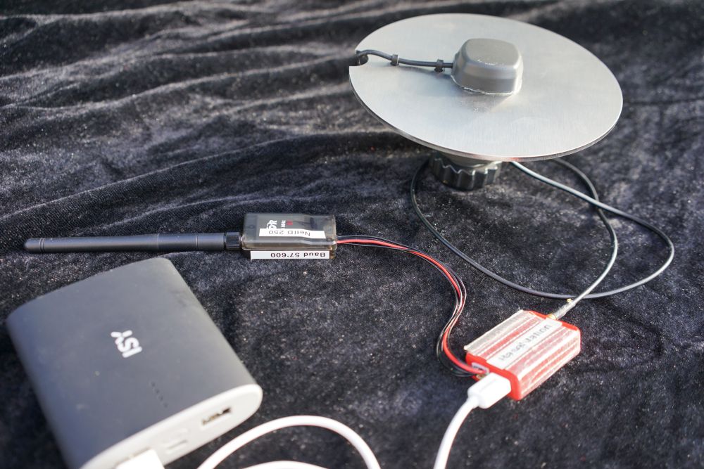
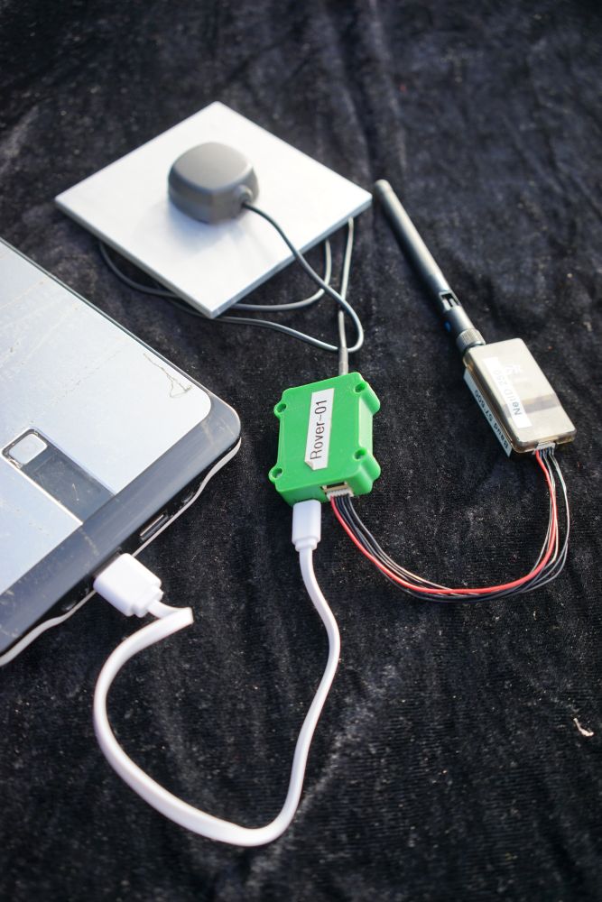
As far as I see from the photos, you use 6 wires to connect the radio. Please try only with 5V, GND, RX and TX. Radio has CTS and RTS on the other two legs and it might be confused by their state.

Apart from that, the only issue possible is cabling itself, that happens sometimes with DF13 connectors.

Looking forward to your answer.

Hi @artem.fomenko

Thank you very much for the replay.

Power consumption:

  • Would it make sense, if I change from PowerBanks to USB-AC/DC-Adapters for testing puposes? I have two adapters with an output of 5V and 2A. Could that help to isolate the issue?

Substitution of radios:

  • Yes, I tried a second pair of radios. Same behaviour. But will try again with the power-adapters mentioned above.

Cabeling:

  • Will check and let you know.

Keep you updated during the next days.

Cheers,
Yvo

Yvo,

Please, try out the same setup with 5V 2A adapters and keep us posted on your progress.

Hi @artem.fomenko

I changed and tried the following steps:

Cabling of the 3DR-radios with DF13-cables:

  • As defined in the docs, only the 5V, TX, RX and GND are connected.
  • Changing both cable with a second different set of DF13-cables.

Powering:

  • PowerBank with 2.1A and 2.5A.
  • PowerAdapter with each 2.0A.

Different radios:

  • Two different sets of radios.

Check of LED-status of radios:

  • In all constellations, both radios showed a solid green LED. According to the documentation, it shows an established link between two radios.
  • But no flashing red LED indicating data-transfer.

ReachView:

  • All settings still the same as defined in the first post.

Result:

  • Still no correction-input at the rover :cry:

Mh, not good.

Questions:

  • Do you have any further ideas or leads to test?
  • Would it make sense to change the baud-rate of the radios? And which value would be best to test / default?

Looking forward for any hints and ideas.

Cheers,
Yvo

Hi @artem.fomenko

I just had an additional idea:

  • Could it be, that the setup of the radios according to this description is not yet satisfying?

I will check it over the coming weekend.

Cheers,
Yvo

Hi @Yvo_Weidmann,

Please, try lowering the baud rate to 9600. By default, it is recommended to use 57600.

I think it is worth establishing a connection between the Reach Modules first and then troubleshooting the ardupilot. However, if the change of the baud rate will help, don’t forget to change it into the ardupilot settings.

Waiting for your feedback.

Hi @artem.fomenko

Mh, very strange. I changed the baud-rate to 9’600 as suggested and I checked the settings in ArduPilot (already set ok).

But I have still no base-correction input. The radios are indicating a link with a solid green LED. But no indication about data-exchange

Additionally, I switched the BaseStation / Rover. No change.

Slowly I a have no more ideas.

Any more hints?

Cheers,
Yvo

PS: I checked the two further possibilities of correction-input:

  • TCP-Correction-Input with a REACH-module as BaseStation - > Works perfectly.
  • NTRIP-Correction-Input using an official correction-service -> Works perfectly.

@Yvo_Weidmann,

We will try to reproduce the issue and come back to you with the feedback as soon as possible. Could you please specify the firmware version you are running?

Hi @artem.fomenko

Currently, the version v2.20.8 is installed. As indicated at the top-right corner of the ReachView application.

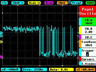
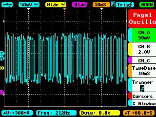
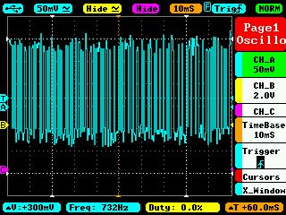
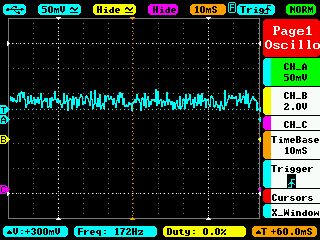
I don’t know, if it is meaningfull, but I checked the serial-outputs of the module in three different status with an oscilloscope (TX and GND). From my understanding it looks ok, does it?

Serial Correction Output On
UART_Serial_CorrectionOutput_4800_01 UART_Serial_CorrectionOutput_4800_02

Serial Position Output On
UART_Serial_PositionOutput_NMEA_4800

No Serial Output
UART_Serial_NoOutput

Cheers,
Yvo

Hi, @Yvo_Weidmann,

Thank you for the oscilloscope pictures. Based on that I could say that the signal shape is the one we expect.

We had replicated the setup and we had not encountered any issues. Could you, please, make sure that the radio connection is the following:

  • TX -> RX
  • RX -> TX
  • GND -> GND
  • 5V -> 5V

So far it looks like there might be an issue with cables or radio itself. Could you, please replace the cable between the Reach module and the radios? I remember asking you to check the cabling, however, I think that is likely the issue.

Also, could you test these radios on another equipment in order to eliminate the Reach from the setup? We also recommend using the latest versions of our firmware (v2.22.4), available in the ReachView app.

Hi @artem.fomenko

I started from scratch and was soldering all cables according your replay. I totally missed the crossed cables of TX and RX.
That was caused because I was using the original cables.

I am sorry for the current issue. It works perfectly and very stable now.

All the best,
Yvo

5 Likes

This topic was automatically closed 100 days after the last reply. New replies are no longer allowed.