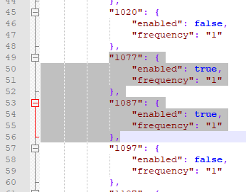
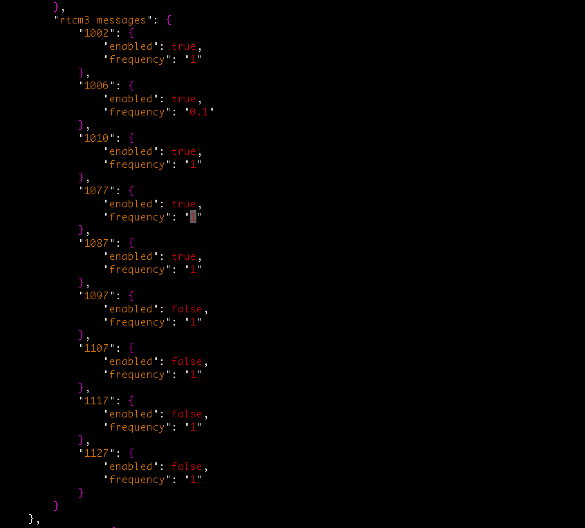
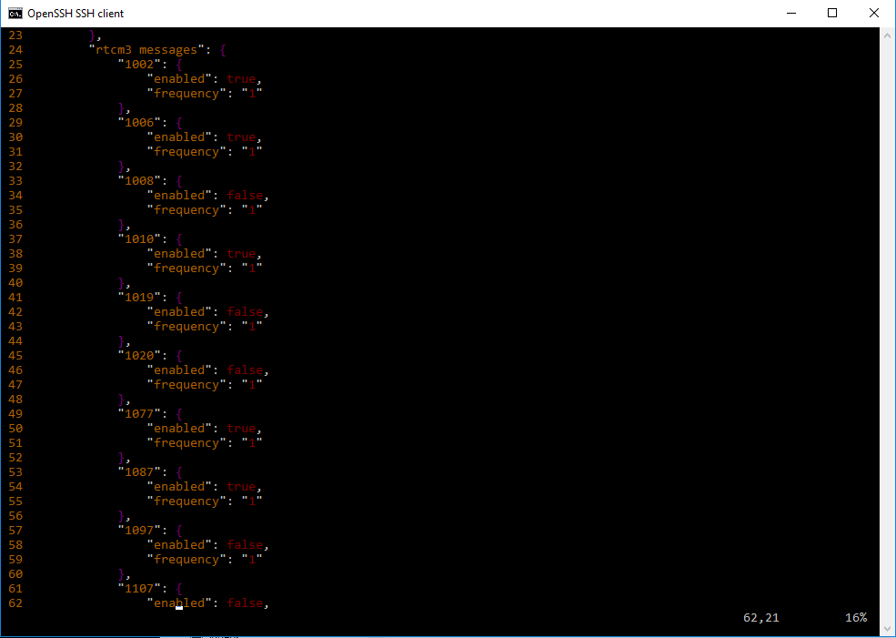
I am interfacing with a device that requires the 1077 and 1087 RTCM 3 commands. There are options to send these “Type 7” messages different formats (1097:Galileo, 1107:SBAS/WAAS, 1117:QZSS, 1127:BeiDou).
I believe the ublox chip onboard the Reach RS is capable of generating these messages. Is there a way to configure the Reach RS do this?
Thanks for your reply!
I guess what I am really asking is:
“Is there a way to configure the messages outside of ReachView?
Is this a software or a hardware limitation?”
Thanks for your help Tatiana!
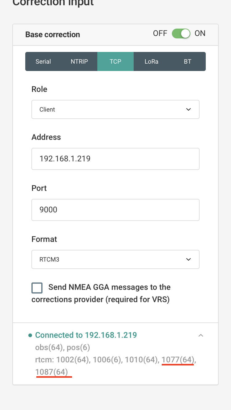
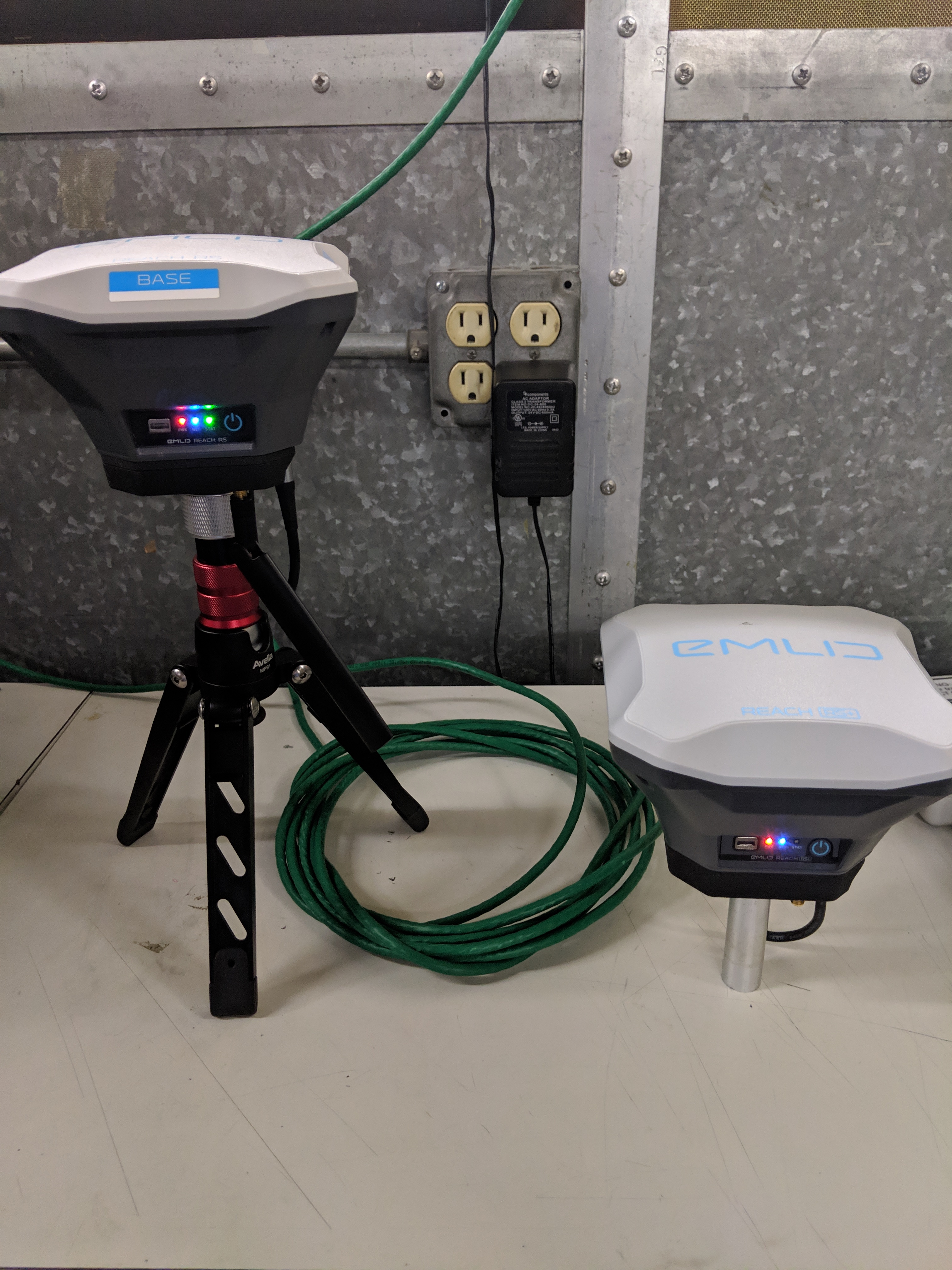
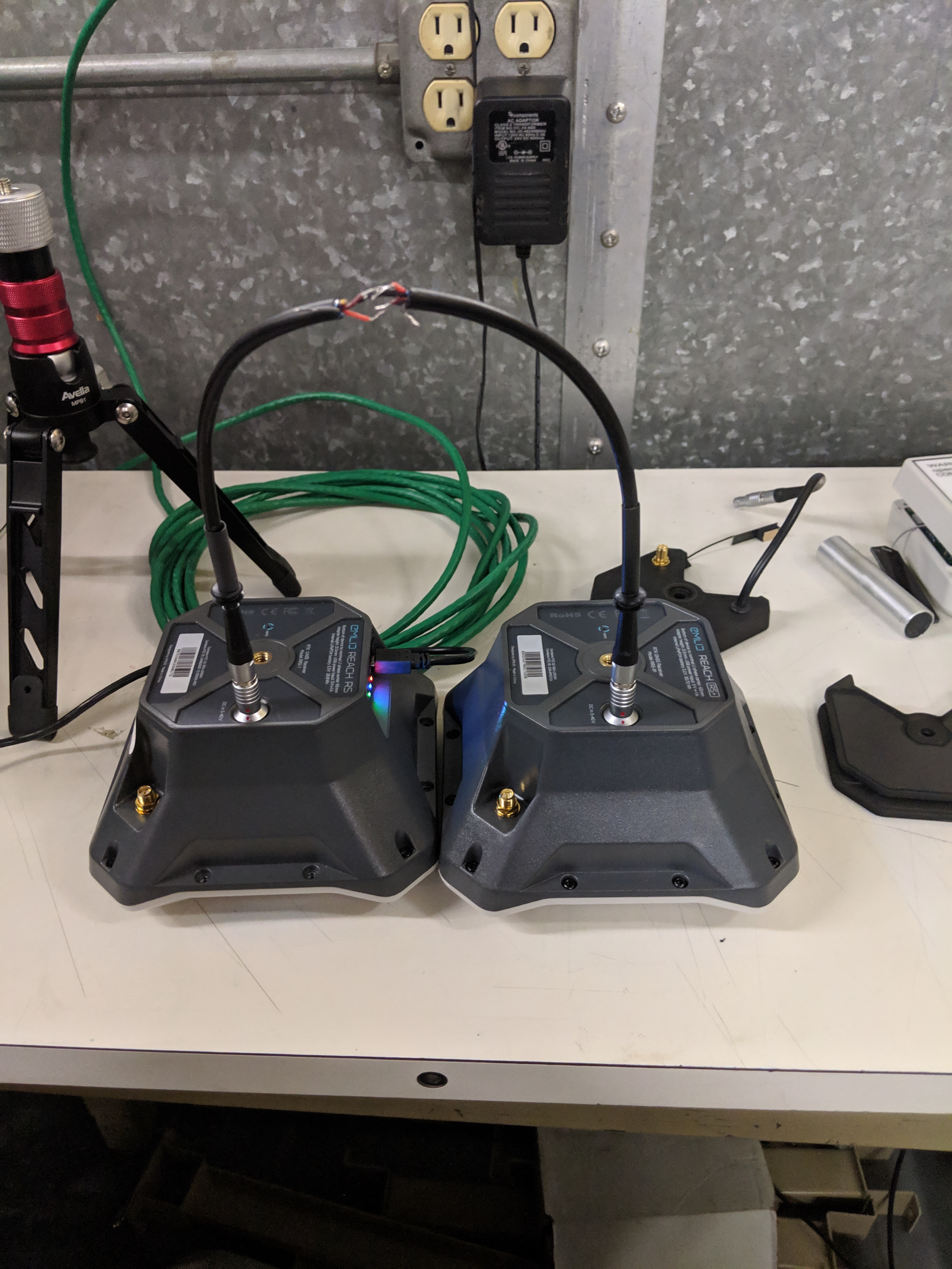
However I did try this method already and while this does work for the TCP connection I require the 1077 and 1087 to be output to the serial port. I have a pair of radio modules. One plugs in to the reach. the other is in another device along with a ublox neo m8p.
Your input is greatly appreciated. Thanks again!
Edit: I am in in a screen room with a GPS repeater. It is not the best setup but it is very repeatable. Also I made sure I was transmitting by probing the serial connection and viewing the rtcm messages as they were being sent from the Reach.
Edit 2: The most interesting thing is that I am getting correction data and it is being saved on the Reach. I can share those logs with you if you think that would help
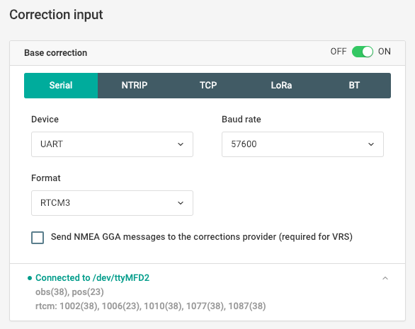
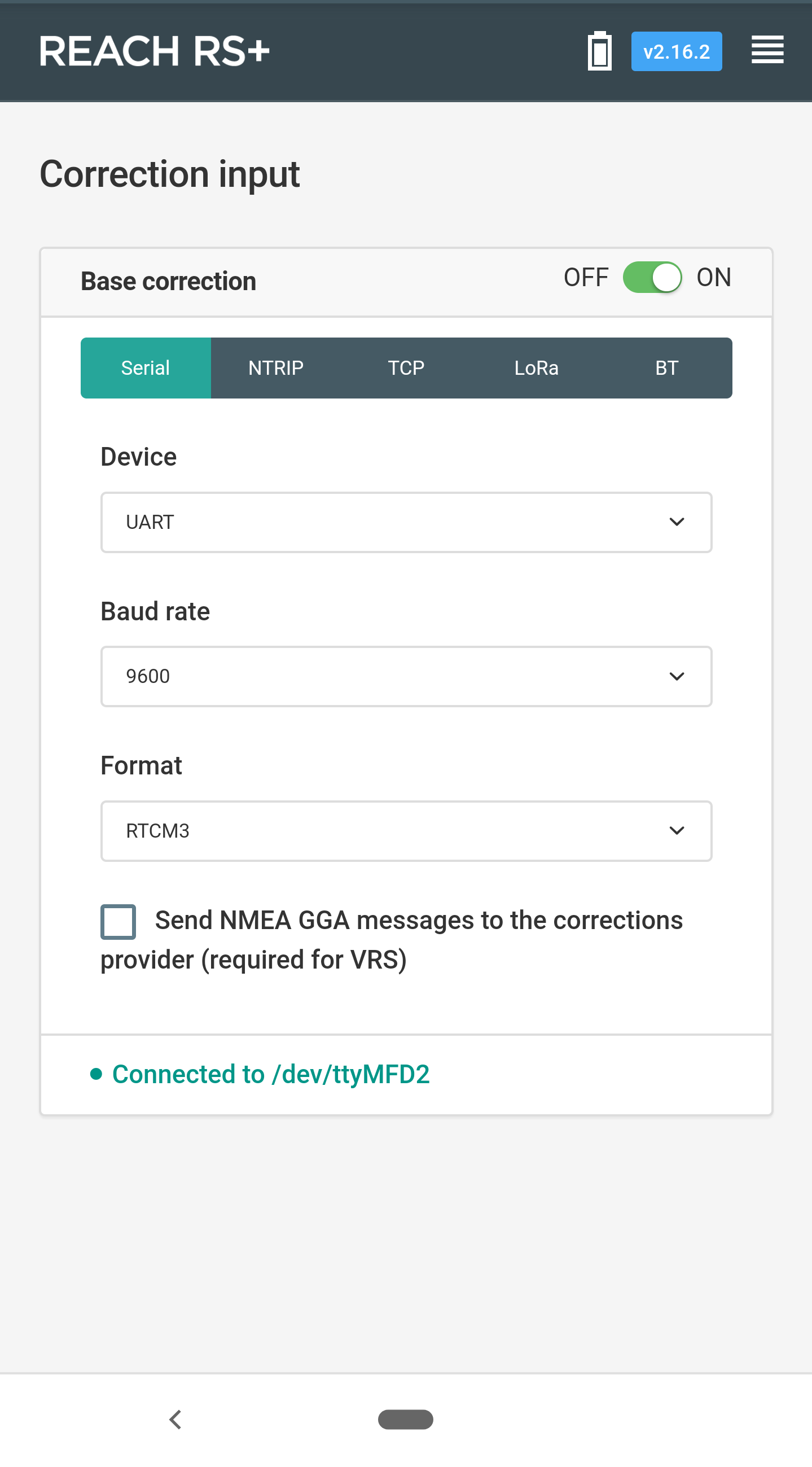
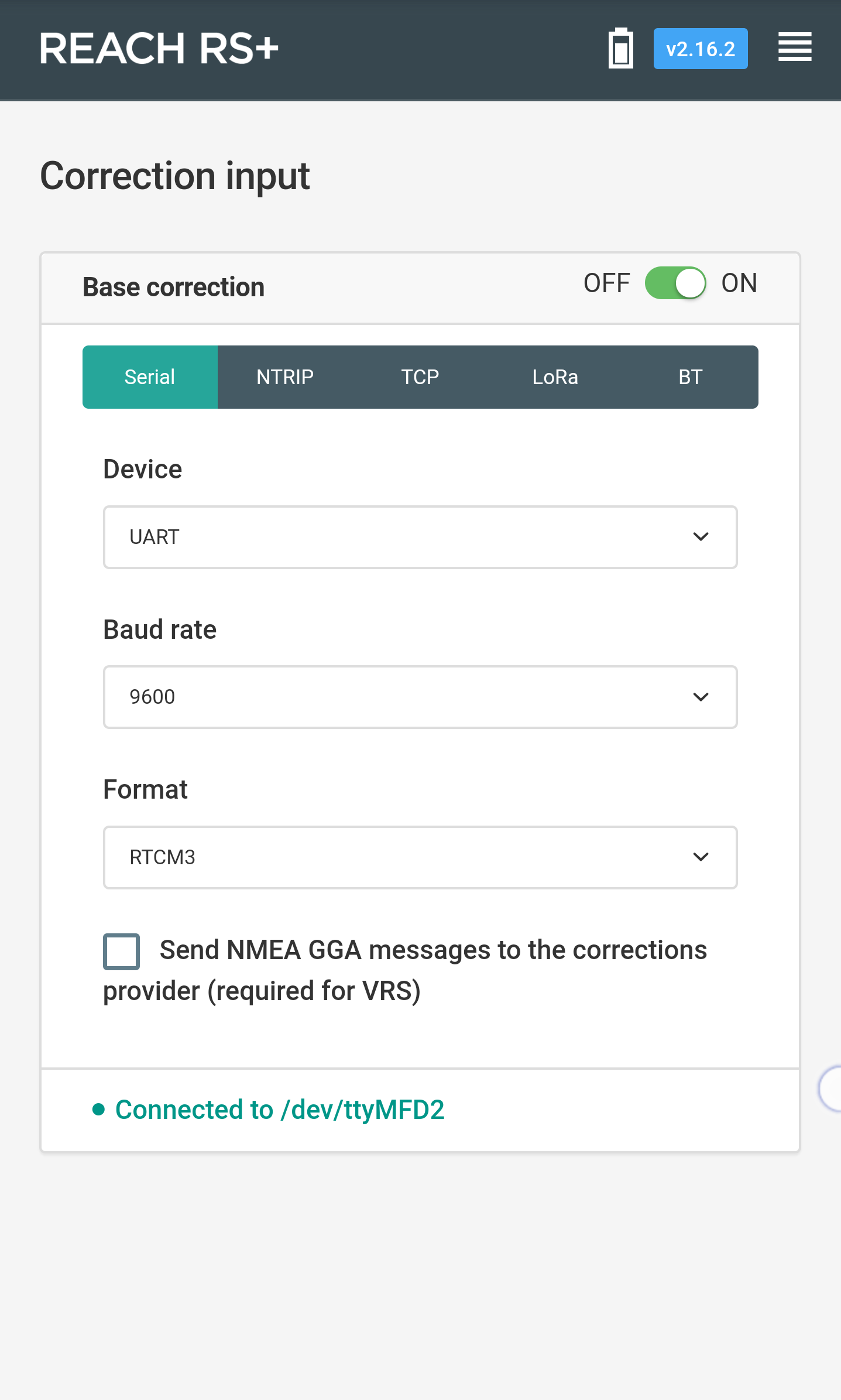
As I can see from the last screenshot, there are no corrections at all. The message “Connected to /dev/ttyMFD2” is showed always when Serial input is enabled.
It means there is no link between the base and rover.
Could you please double-check you’ve connected radios in the proper way? Now it looks like a connection issue.
I’d also recommend you to connect one Reach unit to another over RS-232 to make sure the issue isn’t from receivers side.
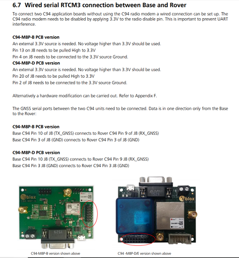
I spent a few hours trying to get this up and running with the ublox C94-M8P. I followed the instructions in the application guide for a wired connection between two C94-M8Ps
I tried this with both of the Reach RS units I have to no avail.
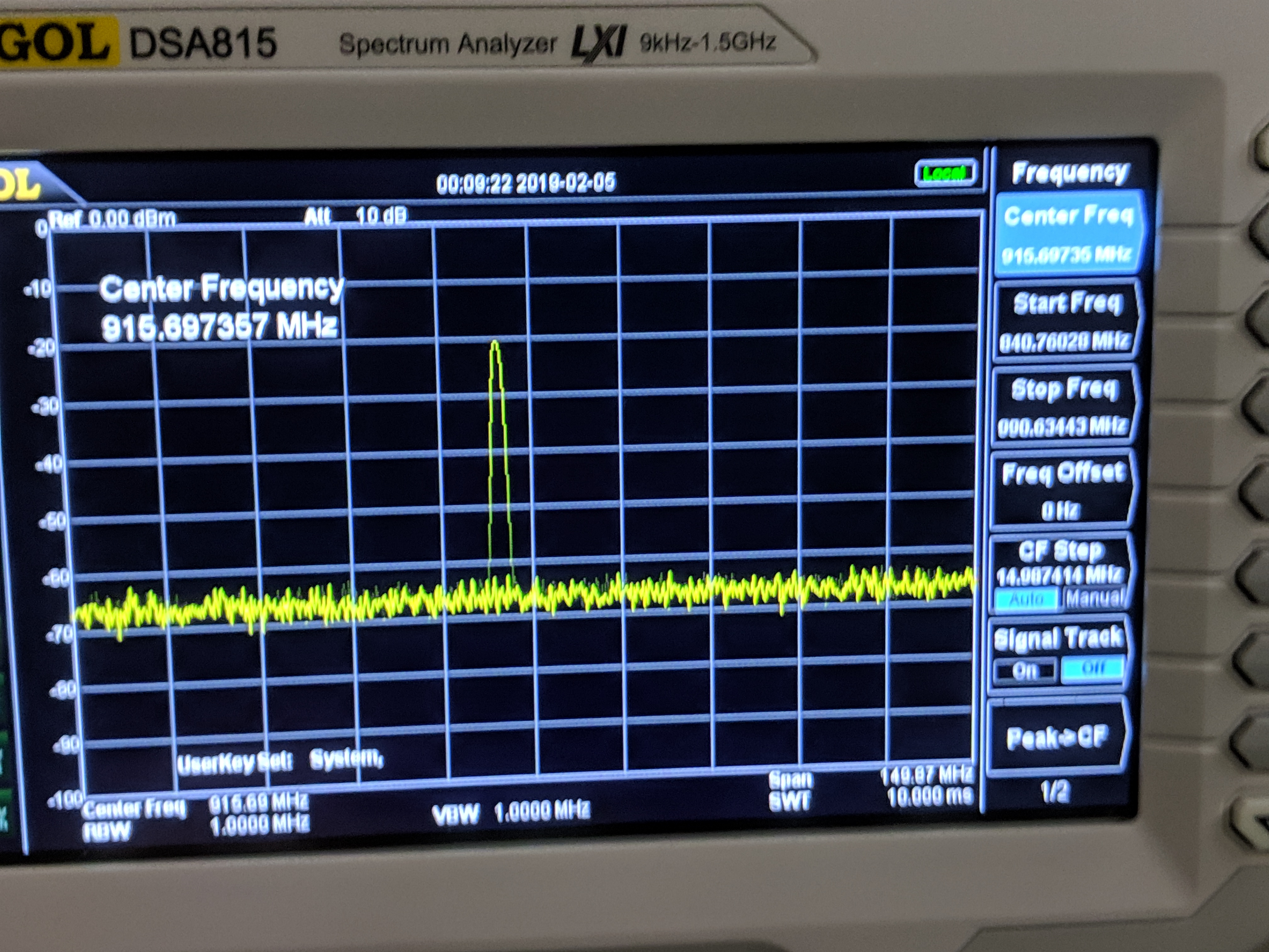
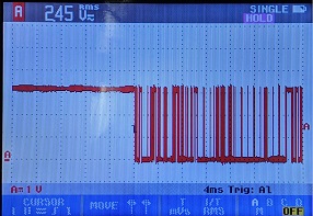
I went ahead and recorded the waveforms and measured the baud rate.
Waveform looks ok. Two things of note,
It is held high and then pulled low to communicate.
2)The logic is at 3 volts unloaded
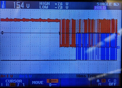
I decided to see how this compared to the Reach RS output (TX):
Surprise! it is different!
It is idle at -7.5 volts and pulled to +7.5 to communicate
So I ran into the difference between TTL and RS-232. So embarrassing.
All this time it was a protocol difference I did not even think about. I threw together an RS-232 to TTL converter and everything works just fine. Corrections are being received by my device. I am glad I found this although still a bit frustrated with myself it took so long.