ReachView - Getting Started

Been reading the FAQ’s, Documentation, using search. Still managing to come up with what appear to be basic questions that I somehow just haven’t spotted any clear explanations for

I have purchased a Reach RTK in used condition off of ebay, without the antenna or cables or anything beyond the bare module itself and it’s cardboard box. The ReachView app reported it’s version as 0.4.6, which I have since updated to 2.9.1. I purchased a GPS-only kit antenna, just to get going with. I am assuming that this antenna will not be good enough in short order as the status page SNR graph only shows one signal in green and the live map shows a point cloud looking about as precise as what I would expect to get from my Garmin GPSMAP64

For trial testing, I set the rig outside on my roof and attempted changing the settings for a static stand-alone mode without any outside source of corrections, as I will need this to function as the fixed base-station in a remote area 5 miles beyond any cell signal and 20 miles from the nearest data-capable cell signal

Didn’t spend a lot of time before updating, but the old app version seemed more intuitive for myself to understand, so now for a few questions

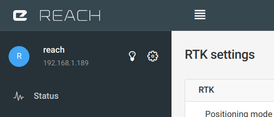
On the sidebar, next to the gear icon for settings, there is an icon that looks like a lightbulb. When I hover over it, no message box pops up to explain it’s purpose, clicking on it makes it blink like something is happening. Nothing has quit working and the RTK module didn’t immediately begin generating magic smoke

So what else could this icon be used for?

I set Base mode/Base coordinates to ‘Average single’. This results in a convincing looking set of numbers, but on changing back to the Status page the ‘Base position’ line remains all zeros. I was assuming this line reports on the modules base position? Is it for the position of an external source of corrections? Something broken? Need that better antenna? Documentation does not explain the underlying logic for how this line is filled-in

This module is supposed to have an onboard 3-axis accelerometer. In: 'RTK settings/Max acceleration, I set both settings to zero, yet the status page still shows accelerations in all axes? Does this mean the status line is for apparent velocity based on GPS fixes? Why isn’t there any page to show live readings on the onboard sensors? Are they disabled? If so, does this mean the maximum velocity settings are for GPS based calculations of movement? And when will this module get inertial navigation? I’ve had an idea about 5 years now that requires this type of data in a handheld GPS receiver. Be nice to see if it can be done here, finally!

Status page shows ‘RTK parameters’, with three stats shown. Each of these has a colored circle underneath. No explanations given as to what the colors mean, or how they are chosen. Also, no clear explanation on if these parameters are determined by any settings changes I make or if this is something being measured. Currently showing as all zero’s/green-red-green

On the ‘Base mode’ page, I keep seeing the position being recalculated, even though I have not restarted the module. It’s been continuously powered-on about 35 hours now. Would have been longer except for a technical issue with circuit breakers. Am thinking about doing the battery-pack portion of this project sooner than later & adding in a continuous charger for testing purposes

Also on this page, there’s a list of RTCM3 message types that I can select. Any chance that interface can be changed to have each type link to a wiki-page for people like myself who are still learning what RTCM is all about? I tried googling a few of those, but I have to wade through a ton of sales pitches giving me anything but relevant information. I know this can be done because on the ‘Camera control’ page, there is a link explaining what the ‘time mark pin’ is - though unfortunately this link appears to be broken as it gets a redirect to the introduction section of the documentation, leaving me to searching the online site. Perhaps an update is needed to have the link pointing to the right sub page?

Reminds me of something else. My original reason for buying this RTK module is to transmit corrections from my own base station to a handheld Garmin GPSMAP64, which states in it’s documentation that it accepts ‘RTCM’ messages but Garmin documentation does not make it clear which version it accepts or what message types. Anyone here happen to know anything about such interfacing issues? Possibly a question for the Groundspeak forum…

If you see that I did not ask about other items concerning the ReachView application, it’s either that they were sufficiently obvious enough or that I didn’t know enough to question! Thank you

You only provided your previous ReachView version. Please state your current ReachView version so future readers of this topic can relate better.


The lightbulb icon is useful for people who have more than one Reach. It just makes the LED blink so you can visually confirm which unit that you are configuring.

https://community.emlid.com/uploads/default/original/2X/3/3267ee50e906ddf91f795f605314b066802e4287.png


When using your Reach as a base, you should provide the known location of your base. If you do not know the location, then you can tell ReachView to “Average single” which averages the single-mode coordinate over a specified period of time and then fills in the base coordinate fields with the result.

The base coordinate on the status page is unrelated. It only appears when you are receiving corrections from a remote base.


The hardware is there, but that feature is not implemented in the ReachView software. The max acceleration settings are unrelated. You can set them to tell the RTK engine what kind of accelerations are expected to be normal (land survey = very low; racing drone = very high).


You can find the answer to that in the docs:
https://docs.emlid.com/reach/common/reachview/base-mode/#rtcm3-messages

1 Like

Edited the post to include my current version

Ok, so it’s really just what I had thought: That one episode of the ‘Simpsons’ where Homer is wondering what the 2nd lightswitch does near his front door. Only in my case, it’s this module up on my roof I keep lighting up every time I feel like clicking on that ‘strobe action thingie’!

2nd question not quite answered, sorry! But I had figured out most of that workflow, just only after looking at the RTCM message type link saw that there’s a ‘save to manual’ icon I just hadn’t tried out yet. The question here being why does the Status page show all zero’s for base position even when I have switched to a manual base position?

4th question also remains, looks like more re-reading the doc page & perhaps searching the www

Looks like I might also want to read, or read about, this ‘RTCM STANDARD 10403.3’. If only the local library had a copy of that! But I guess I wasn’t diligent enough in reading the documentation. I know I skimmed through that at least once, just didn’t remember seeing that section & failed to get back to it. The tips there are good to know too, thanks!

:+1:

This may help: Your Reach can be a base. Your Reach can be a rover. Your Reach can be a base and a rover at the same time.

Now, If you are using your Reach as a rover, and are receiving corrections from a remote base, then that remote base location will show on the status page.

If you are using your Reach as a base, then the coordinate entered in the Base mode page will be encoded in an RTCM3 message and sent. And then if you have a Reach rover receiving those RTCM3 messages then that is the place where your base coordinate will appear (on the rover status page).


If you only have one Reach, and you want to see what it would look like if you had base corrections coming in, then although useless, you could set up base correction TCP output on a port (say 9090), and set up rover correction input to connect by TCP to 127.0.0.1 port 9090. Then Reach would be eating it's own tail and in the status page you would see grey bars and you would also see your base coordinate appear. Let me reiterate though, aside from demonstrating what receiving base corrections 'looks like,' this serves no useful purpose at all.

Ok, so that section is only for remote base positions. Probly would’ve noticed that if I had tried setting up a corrections source. Guess it wouldn’t hurt to experiment with that here at the house

I understood the ‘useless’ nature of that exercise well before reading your reiteration! Recognized 127.0.0.1 as a loopback. But all the same, it’s somehow reassuring that I can do such a thing and not brick the module! Right at the moment I’m looking into how to locate the nearest source of NTrip data, and then how to set that up

Sorry, please don’t take offense. It’s not that I doubt your understanding. I’m trying to write for the audience as well.

Setting up an NTRIP source will be better than a loopback for sure.

No problem! Some of that audience may not know why 127.0.0.1 acts like it does

But as for finding a NTRIP source, seems like I need that 2nd Reach and just make my own source. Having fun trying to figure out how to locate a source I can access

Why ‘grey bars’? What does that represent? Corrected signals? Makes me think like it’s a ghost of a signal, which is what I think GPS is to start with!

I couldn’t as yet find a useable corrections source in my area, so I tried a different sort of ‘useless’ experiment. At: http://www.scign.org/realtime/ntrip/access I tried using the ALPP_RTCM3 mountpoint, which makes ReachView much more interesting for trial purposes

Baseline is almost 1500 kilometers. Pointcloud on the map view looks like I’m getting better than 2 meter accuracy, whereas before I was averaging about 20 meters

So, even with the wrong corrections source and a very poor antenna setup, a big improvement in immediate usefulness plus now I’m getting a more clear understanding of how the interface works

1 Like

The coloured bars represent your local unit (rover), and the grey bars are those of the remote unit (base). It is good information to have.

One example is that you might have six ‘green’ bars at the base and at the rover - good enough to get a fix, right? Well,if you see them side-by-side on the screen then you can tell that the six green base satellites are maybe not the same satellites as the six green rover satellites. Really you only have four green satellites in common, and that is why you are having difficulty getting a fix.

Another example is if a bird sat on your base antenna and messed up your reception, or if the wind or a vandal or an animal knocked it over, then you can immediately tell that something is wrong.

1 Like

This topic was automatically closed 100 days after the last reply. New replies are no longer allowed.